Page is loading ...

P/N 126718-01 Rev. N 04/2020
P126718-01
Ce manuel est disponible en francais, simplement
en faire la demande. Numéro de la pièce 126718-02.
- Do not store or use gasoline or other flammable
vapors and liquids in the vicinity of this or any
other appliance.
- WHAT TO DO IF YOU SMELL GAS
• Do not try to light any appliance.
• Do not touch any electrical switch; do not use
any phone in your building.
• Leave the building immediately.
• Immediately call your gas supplier from a neigh-
bor’s phone. Follow the gas supplier’s instruc-
tions.
• If you cannot reach your gas supplier, call the
fire department.
- Installation and service must be performed by
a qualified installer, service agency or the gas
supplier.
WARNING:
FIRE OR EXPLOSION HAZARD
Failure to follow safety warnings exactly could
result in serious injury, death, or property damage.
AVERTISSEMENT:
RISQUED’INDENDIE OU D’EXPLOSION
Le non-respect Des avertissements de sécurité
pourrait d’entraîner des blessures graves, la mort
ou des dommages matériels.
- Ne pas entreposer ni utilizer d’essence ni d’autres
vapeurs ou liquides inflammables dans le voisinage
de cet appareil ou de tout autre appareil.
- QUE FAIRE SI VOUS SENTEZ UNE ODEUR DE GAZ:
• Ne pas tenter d’allumer d’appareil.
• Ne touchez à aucan interrupteur. Ne pas vous servir
des téléphones se trouvant dans le bâtiment où
vous trouvez.
• Sortez immédiatement de bâtiment.
• Appelez immédiatement votre fournisseur de
gaz depuis un voisin. Suivez les instructions du
fournisseur.
• Si vous ne pouvez rejoindre le fournisseur de gaz,
appelez le service des incindies.
- L’installation et l’entretien doivent être assurés par
un installateur ou un service d’entretien qualifié
ou par le fournisseur de gaz.
NOTE: DIAGRAMS AND ILLUSTRATIONS THROUGHOUT THE MANUAL ARE NOT TO SCALE.
INSTALLER: Leave this manual with the appliance.
CONSUMER: Retain this manual for future
reference.
Installateur : Laissez cette notice avec l’appareil.
Consommateur : Conservez cette notice pour
consultation ultérieure.
This appliance may be installed in an aftermarket permanently located, manufactured home (USA only) or
mobile home, where not prohibited by local codes. This appliance is only for use with the type of gas indicated
on the rating plate. This appliance is not convertible for use with other gases, unless a certified kit is used.
Cet appareil peut installé dans une maison préfabriquée (mobile) déjà installée à demeure, si les réglements
locaux le permettent. Ce appareil doit être utilisé uniquement avec le type de gaz indiqué sure la plaque
signalétique. Cet appareil ne peut être converti à d’autres gaz, sauf si une trousse de conversion est utilsée.
Installation and Operation Instructions
DRL4500 Series Direct-Vent Linear Gas Fireplace
Models
DRL4543TEN
DRL4543TEP
Report No. F11 -026
PFS
®
USC

SuperiorFireplaces.us.com 126718-01N2
DANGER
HOT GLASS WILL
CAUSE BURNS.
DO NOT TOUCH GLASS
UNTIL COOLED.
NEVER ALLOW CHILDREN
TO TOUCH GLASS.
A barrier designed to reduce the risk of burns from the hot viewing glass is pro-
vided with this appliance and must be installed for the protection of children and
other at-risk individuals.
DANGER
PELIGRO
VITRE CHAUDE
RISQUE DE BRÛLURES.
NE TOUCHEZ PAS UNE VITRE
NON REFROIDIE.
NE LAISSEZ JAMAIS UN ENFANT
DE TOUCHER LA VITRE.
EL VIDRIO CALIENTE
CAUSARÁ QUEMADURAS.
USTED DEBE NUNCA
TOCAR EL VIDRIO CALIENTE.
LOS NIÑOS DEBEN NUNCA
TOCAR EL VIDRIO.
L’écran pare-étincelles fourni avec ce foyer réduit le risque de brûlure en cas de
contact accidentel avec la vitre chaude et doit être installé pour la protection Des
enfants et Des personnes à risques.
Se provee con este aparato una barrera de proteccion (malla), diseñada para reducir
el riesgo de quemaduras por contacto accidental con el vidrio caliente que debe
estar instalada para proteccion de infantes y otros individuos en riesgo.
Vea el volante adjunto para la representación de color adecuado
See attached color flyer for proper color representation
Voir ci-joint tract pour une bonne représentation de la couleur
SAFETY AND YOUR FIREPLACE

SuperiorFireplaces.us.com126718-01N 3
Afin d’éviter les brûlures
graves ou les blessures,
ne pas retirer l’écran de
protection de la foyer qui
empêche tout contact
direct avec la vitre.
Para evitar quemaduras y lesiones
graves, no quite el protector de malla
o guardia de seguridad que evita el
contacto directo con el vidrio.
Seguridad y su
chimenea
La sécurité et
votre foyer
[FRENCH][ENGLISH]
[SPANISH]
Safety and Your
Fireplace
To prevent severe burns
and injuries, do Not remove
the barrier on the appliance
which prevents direct
contact with the glass.
All parts of your
IHP fireplace get
EXTREMELY HOT!
Toutes les parties de votre
foyer IHP deviennent
EXTRÊMEMENT CHAUDES !
¡Todas las partes de la
chimenea IHP se ponen
MUY CALIENTES!
Follow the safety instructions
below and be sure everyone in your
household understands this burn
hazard:
• The surfaces on your fireplace get
EXTREMELY HOT!
• The glass on the front of the
fireplace reaches EXTREMELY HIGH
temperatures and can cause severe
burns if touched.
• Keep children away from an
operating fireplace. Closely
supervise children in any room
where a fireplace is operating to
prevent contact with glass.
• Keep clothing, furniture, gasoline,
and other flammable liquids away
from the fireplace.
• Even after the gas is turned
off, fireplace surfaces remain
extremely hot.
Be sure to attach the enclosed Safety-
in-Operation Warnings where you
turn on your fireplace, to help remind
everyone of the dangers associated
with high temperatures
(Page 34)
.
Read Important Safety Information
(Page 4)
.
Suivez les instructions de sécurité
ci-dessous et veillez à ce que tous
les membres de votre famille soient
conscients du danger de brûlure
encouru :
• Les surfaces de votre foyer
deviennent EXTRÊMEMENT CHAUDES
!
• La vitre située à l'avant du
foyer atteint des températures
EXTRÊMEMENT ÉLEVÉES et peut
causer de graves blessures en cas de
contact.
• Tenez les enfants à l'écart du foyer
lorsqu'il fonctionne. Surveillez
attentivement les enfants dans les
pièces où un foyer est utilisé afin
d'éviter qu'ils ne soient en contact
avec la vitre.
• Tenez tous les vêtements, les
meubles, l'essence et tout autre
liquide inflammable à l'écart du foyer.
• Même après fermeture du gaz, les
surfaces du foyer restent extrêmement
chaudes.
Veillez à coller les Étiquettes de mise
en garde relatives à la sécurité
d'utilisation à l'endroit où vous
utilisez le foyer, pour rappeler à tous
les utilisateurs les dangers liés aux
températures élevées
(Page 34)
.
Lisez L’information de sûreté
importante (Page 4)
.
Siga las instrucciones de seguridad
a continuación y asegúrese de que
todos en su hogar sepan acerca de
este peligro de quemadura:
• ¡Las superficies de la chimenea se
ponen MUY CALIENTES!
• El vidrio delante de la
chimenea alcanza temperaturas
EXTREMADAMENTE ALTAS y puede
causar quemaduras graves si se toca.
• Mantenga a los niños alejados de
la chimenea en funcionamiento.
Supervise en forma cercana a los
niños en cualquier cuarto donde
haya una chimenea funcionando para
impedir el contacto con el vidrio.
• Mantenga la ropa, mobiliario,
gasolina y otros líquidos inflamables
alejados de la chimenea.
• Aún después de haber apagado el
gas, las superficies de la chimenea
permanecen extremadamente calientes.
Asegúrese de colocar las Etiquetas
de advertencia de seguridad de
operación en el lugar donde enciende
la chimenea, para que todos recuerden
los peligros asociados con las altas
temperaturas
(Página 34)
.
Lea Información importante de
seguridad (página 4).

SuperiorFireplaces.us.com 126718-01N4
SAFETY
WARNING: Improper installation, adjustment,
alteration, service or maintenance can cause injury
or property damage. Refer to this manual for correct
installation and operational procedures. For assis-
tance or additional information consult a qualified
installer, service agency or the gas supplier.
This appliance is only for use with the type of gas
indicated on the rating plate. This appliance is not
convertible for use with other gases, unless a certi-
fied kit is used.
State of Massachusetts: The installation must be
made by a licensed plumber or gas fitter in the Com-
monwealth of Massachusetts.
WARNING: This product can expose you to
chemicals including Carbon Black, which is known to
the State of California to cause cancer, and Carbon
Monoxide, which is known to the State of California
to cause birth defects or other reproductive harm. For
more information go to www.P65Warnings.ca.gov.
IMPORTANT: Read this owner’s manual carefully and
completely before trying to assemble, operate or
service this fireplace. Improper use of this fireplace
can cause serious injury or death from burns, fire,
explosion, electrical shock and carbon monoxide
poisoning.
DANGER: Carbon monoxide poisoning may lead
to death!
WARNING: Do not slam or strike glass doors.
Damage can result in a hazardous condition.
Young children should be carefully supervised when they are in
the same room as the appliance. Toddlers, young children and
others may be susceptible to accidental burns. A physical barrier
is recommended if there are at-risk individuals in the house.
To restrict access to a fireplace or stove, install an adjustable
safety gate to keep toddlers, young children and other at-risk
individuals out of the room and away from hot surfaces.
This vented gas fireplace is a sealed combustion gas fireplace de-
signed for residential applications. This fireplace must be installed
with INNOVATIVE HEARTH PRODUCTS (IHP) vent pipe components
and terminations.
NOTICE: Decorative product not for use as a heating
appliance.
Thank you for your purchase. We appreciate your business!
Please carefully read and follow all instructions in this manual. Pay special attention to all warnings and safety information.
Following these safety, care, and operation instructions will help ensure many years of dependable and enjoyable service from your
fireplace.
Please read and understand these instructions before installing or operating.
TABLE OF CONTENTS
Safety and Your Fireplace ............................................................... 2
Local Codes ...................................................................................7
Product Identification ..................................................................... 7
Product Features ............................................................................8
Requirements for the Commonwealth of Massachusetts ..............8
Pre-installation ...............................................................................9
Location of Termination Cap ........................................................12
Venting Installation ......................................................................13
Fireplace Installation ....................................................................25
Installer - Attaching Safety In Operation Warnings.......................32
Operation ....................................................................................33
Homeowner - Attaching Safety In Operation Warnings................34
Inspecting Burners ....................................................................... 35
Cleaning and Maintenance ...........................................................36
Replacing Light Bulbs ..................................................................36
Gas Control Module System ........................................................37
Remote Control Operation ...........................................................37
Specifications ...............................................................................39
Wiring Diagram ............................................................................40
Troubleshooting ...........................................................................41
Parts ............................................................................................43
Replacement Parts .......................................................................47
Technical Service .........................................................................47
Service Hints ................................................................................ 47
Accessories .................................................................................. 47
Warranty ......................................................................................49
WARNING
Never connect this appliance to private (non-utility) gas
wells. This gas is commonly known as wellhead gas
and does not have odorants and may have impurities,
and variations in BTU content. The use of well-head gas
will void the manufacturer’s warranty to this appliance.

SuperiorFireplaces.us.com126718-01N 5
Important Safety Informa-
tion
1. WARNING: Do not operate appliance
with the glass front removed, cracked,
or broken.
2. Do not use this appliance if any part
has been under water. Immediately
call a qualified service technician to
inspect the appliance and to replace
any part of the control system and
any gas control which has been under
water.
3. Due to high temperatures, the appli-
ance should be located out of traffic
and away from furniture and draperies.
4. Children and adults should be alerted
to the hazards of high surface tem-
perature and should stay away to avoid
burns or clothing ignition.
5. Clothing or other flammable material
should not be placed on or near the
appliance.
6. Young children should be carefully
supervised when they are in the same
room as the appliance. Toddlers,
young children, and others may be sus-
ceptible to accidental contact burns.
A physical barrier is recommended
if there are at-risk individuals in the
house. To restrict access to a fireplace
or stove, install an adjustable safety
gate to keep toddlers, young children,
and other at-risk individuals out of the
room and away from hot surfaces.
7. Any safety screen, guard or barrier
removed for servicing an appliance
must be replaced prior to operating
the appliance.
8. Installation and repair should be done
by a qualified service person. The
appliance should be inspected before
use and at least annually by a profes-
sional service person. More frequent
cleaning may be required due to
excessive lint from carpeting, bedding
material, et cetera. It is imperative
that control compartments, burners,
and circulating air passageways of the
appliance be kept clean. See mainte-
nance instructions on Page 36.
L’information de sûreté
importante
1. AVERTISSEMENT. Ne pas utiliser l’appareil
si le panneau frontal en verre n’est pas en
place, est craqué ou brisé.
2. Ne pas se servir de cet appareil s’il a été
plongé dans l’eau, même partiellement.
Faire inspecter l'appareil par un technicien
qualifié et remplacer toute partie du systéme
de contrôle et toute commande qui ont été
plongées dans l'eau.
3. En raison des températures élevées,
l’appareil devrait être installé dans un
endroit où il y a peu de circulation et loin
du mobilier et des tentures.
4. Les enfants et les adultes devraient être
informés des dangers que posent les tem-
pératures de surface élevées et se tenir à
distance afin d’éviter des brûlures ou que
leurs vêtements ne s’enflamment.
5. On ne devrait pas placer de vêtements
ni d’autres matières inflammables sur
l’appareil ni à proximité.
6. Les jeunes enfants devraient être surveillés
étroitement lorsqu’ils se trouvent dans la
même pièce que l’appareil. Les tout petits,
les jeunes enfants ou les adultes peuvent
subir des brûlures s’ils viennent en contact
avec la surface chaude. Il est recommandé
d’installer une barrière physique si des
personnes à risques habitent la maison.
Pour empêcher l’accès à un foyer ou à un
poêle, installez une barrière de sécurité
; cette mesure empêchera les tout petits,
les jeunes enfants et toute autre personne
à risque d’avoir accès à la pièce et aux
surfaces chaudes.
7. Tout écran ou protecteur retiré pour per-
mettre l’entretien de l’appareil doit être
remis en place avant de mettre l’appareil
en marche.
8. L’installation et la réparation devrait être
confiées à un technicien qualifié. L’appareil
devrait faire l’objet d’une inspection par un
technicien professionnel avant d’être utilisé
et au moins une fois l’an par la suite. Des
nettoyages plus fréquents peuvent être
nécessaires si les tapis, la literie, et cetera
produisent une quantité importante de pous
-
sière. Il est essentiel que les compartiments
abritant les commandes, les brûleurs et les
conduits de circulation d’air de l’appareil
soient tenus propres. Voyez les instructions
d’entretien à la Page 36.
Información importante de
seguridad
1. ADVERTENCIA: No opere el artefacto con el
frente de vidrio quitado, agrietado o roto.
2. No use este artefacto si alguna de sus partes
ha estado bajo agua. Llame de inmediato
a un técnico de servicio calificado para
que inspeccione el artefacto y reemplace
cualquier parte del sistema de control y
cualquier control de gas que haya estado
bajo agua.
3. Debido a las altas temperaturas, el artefacto
debe situarse fuera de las áreas de tráfico y
lejos del mobiliario y cortinas.
4. Se debe alertar a los niños y adultos sobre
los peligros de las altas temperaturas en la
superficie y que se mantengan alejados para
evitar quemaduras o ignición de la ropa.
5. No debe colocarse ropa u otros materiales
inflamables sobre y cerca del artefacto.
6. Se debe supervisar de cerca a los niños
cuando estén en el mismo cuarto que el
artefacto. Los niños pequeños, los jóvenes
y otras personas pueden ser susceptibles
a quemaduras por contacto accidental. Se
recomienda instalar una barrera física si hay
personas en riesgo en la casa. Para restringir
el acceso a una chimenea o estufa, instale
una puerta de seguridad ajustable para
mantener a los niños pequeños, jóvenes y
otras personas en riesgo fuera del cuarto y
lejos de las superficies calientes.
7. Cualquier malla o resguardo de seguridad
quitado para dar servicio a un artefacto, debe
reinstalarse antes de operar el artefacto.
8. Una persona de servicio competente debe
realizar la instalación y reparación. Una
persona de servicio profesional debe
inspeccionar el artefacto antes de usar al
menos una vez por año. Se puede requerir
limpieza más frecuente debido a la pelusa
excesiva del alfombrado, del material de
cobijas, etc. Es imprescindible mantener
limpios los compartimientos de control, los
quemadores y los pasajes de circulación del
aire del artefacto. Ver las instrucciones de
mantenimiento en la página 36.
IMPORTANT SAFETY INFORMATION

SuperiorFireplaces.us.com 126718-01N6
This fireplace must be installed by a qualified (certified or licensed)
service person. It brings in fresh air for combustion through the outer
pipe and combustion gases are exhausted through the inner pipe. If
the glass door assembly and venting pipe are not properly seated,
connected and sealed, carbon monoxide leakage (spillage) can occur.
Carbon Monoxide Poisoning: Early signs of carbon monoxide poison-
ing resemble the flu, with headaches, dizziness or nausea. If you have
these signs, the fireplace may not be working properly. Get fresh air
at once! Have fireplace serviced. Some people are more affected by
carbon monoxide than others. These include pregnant women, people
with heart or lung disease or anemia, those under the influence of
alcohol and those at high altitudes.
Natural and Propane/LP Gas: Natural and propane/LP gas are odor-
less. An odor-making agent is added to the gas. The odor helps you
detect a gas leak. However, the odor added to the gas can fade. Gas
may be present even though no odor exists.
Make certain you read and understand all warnings. Keep this manual
for reference. It is your guide to safe and proper operation of this
fireplace.
WARNING: Any change to this fireplace or its con-
trols can be dangerous. Do not modify this fireplace
under any circumstances. Any parts removed for ser-
vicing must be replaced prior to operating fireplace.
WARNING: Do not use a blower insert, heat ex-
changer insert or other accessory not approved for use
with this fireplace.
WARNING: This appliance is only for use with
the type of gas indicated on the rating plate. This
appliance is not convertible for use with other gases
unless a certified kit is used.
WARNING: Do not allow fans to blow directly into
the fireplace. Avoid any drafts that alter burner flame
patterns.
Due to high temperatures, the appliance should be
located out of traffic and away from furniture and
draperies.
Clothing or other flammable material should not be
placed on or near the appliance.
Do not use this fireplace to cook food or burn paper
or other flammable material.
Any safety screen, guard, or barrier removed for
servicing an appliance must be replaced prior to
operating the appliance.
SAFETY Continued
Installation and repair should be done by a qualified
service person. The appliance should be inspected
before use and at least annually by a professional
service person. More frequent cleaning may be re-
quired due to excessive lint from carpeting, bedding
material, etcetera. It is imperative that control com-
partments, burners, and circulating air passageways
of the appliance be kept clean.
Children and adults should be alerted to the hazards
of high surface temperature and should stay away
to avoid burns or clothing ignition.
A barrier designed to reduce the risk of burns from
the hot viewing glass is provided with this appliance
and shall be installed for the protection of children
and other at-risk individuals.
If the barrier becomes damaged, the barrier shall
be replaced with the manufacturer's barrier for this
appliance.
Keep the area around your fireplace clear of combus-
tible materials, gasoline and other flammable vapor
or liquids. Do not run fireplace where these are used
or stored.
1. For propane/LP fireplace, do not place propane/LP supply tank(s)
inside any structure. Locate propane/LP supply tank(s) outdoors.
To prevent performance problems, do not use propane/LP fuel
tank of less than 100 lb. capacity.
2. If you smell gas
• shut off gas supply
• do not try to light any appliance
• do not touch any electrical switch; do not use any phone in your
building
• immediately call your gas supplier from a neighbor’s phone.
Follow the gas supplier's instructions
• if you cannot reach your gas supplier, call the fire department.
3. Never install the fireplace
• in a recreational vehicle
• in windy or drafty areas where curtains or other combustible (flam-
mable) objects can make contact with the fireplace front
• in high traffic areas
4. Turn fireplace off and let cool before servicing, installing or
repairing. Only a qualified service person should install, service
or repair this fireplace. Have fireplace inspected annually by a
qualified service person.
5. You must keep control compartments, burners and circulating
air passages clean. More frequent cleaning may be needed due
to excessive lint and dust from carpeting, bedding material, etc.
Turn off the gas valve and pilot light before cleaning fireplace.

SuperiorFireplaces.us.com126718-01N 7
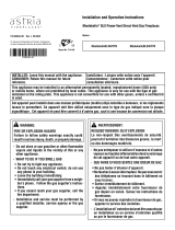
Glass Door
Pebble
Pan
Flue Collar
Nailing
Flange
Access Door
Barrier J7457
Top Spacers
SAFETY Continued
6. Have venting system inspected annually by a qualified service
person. If needed, have venting system cleaned or repaired. See
Cleaning and Maintenance, Page 36.
7. Do not use any solid fuels (wood, coal, paper, cardboard, etc.) in
this fireplace. Use only the gas type indicated on fireplace name-
plate.
8. This appliance, when installed, must be electrically grounded in
accordance with local codes or, in the absence of local codes, with
Listing: This fireplace complies with the National Safety Standards
and is listed and tested by PFS TECO to ANSI Z21.50/CSA 2.22
standard as vented gas fireplace and applicable sections of Z21.97
standard for outdoor decorative gas appliance (When installed as a
see-thru unit using outdoor kit model LDSTO).
These appliances comply with CSA P.4.1-2015 “Testing Method for
Measuring Annual Fireplace Efficiency. P4 (EnerGuide) is a measure-
ment of the Canadian Office of Energy Efficiency.
PRODUCT IDENTIFICATION
Figure 1 - DRL4543 Linear Fireplace
the National Electrical Code, ANSI/NFPA 70 or Canadian Electrical
Code, CSA C22.1.
9. Do not use fireplace if any part has been exposed to or under
water. Immediately call a qualified service person to arrange for
replacement of the unit.
10. Do not operate fireplace with glass door removed, cracked or
broken.
11. Provide adequate clearances around air openings.
LOCAL CODES
Install and use fireplace with care. Follow all local codes. In the ab-
sence to local codes, use the current National Fuel Gas Code ANSI
Z223.1/NFPA 54* (USA) or the current CSA-B149.1 Installation Code
(Canada).
*Available from:
American National Standards Institute, Inc.
25 West 43rd Street, 4th floor
New York, NY 10036
National Fire Protection Association, Inc.
1 Batterymarch Park
Quincy, MA 02169-7471
Based on CSA P. 4.1-2015

SuperiorFireplaces.us.com 126718-01N8
COMMONWEALTH OF MASSACHUSETTS REQUIREMENTS
These appliances are approved for installation in the US state of
Massachusetts if the following additional requirements are met:
• Install this appliance in accordance with Massachusetts Rules
and Regulations 248 C.M.R. Sections 4.00 through 8.00.
• Installation and repair must be done by a plumber or gas fitter
licensed in the Commonwealth of Massachusetts.
• The flexible gas line connector used shall not exceed 36 inches
(92 centimeters) in length.
• The individual manual shut-off must be a T-handle type valve.
REQUIREMENTS FOR THE COMMONWEALTH OF MASSACHUSETTS
Massachusetts Horizontal Vent Requirements
In the Commonwealth of Massachusetts, horizontal terminations
installed less than seven (7) feet above the finished grade must
comply with the following additional requirements:
• A hard wired carbon monoxide detector with an alarm and
battery back-up must be installed on the floor level where
the gas fireplace is installed. The carbon monoxide detector
must comply with NFPA 720, be ANSI/UL 2034 listed and be
ISA certified.
• A metal or plastic identification plate must be permanently
mounted to the exterior of the building at a minimum height
of eight (8) feet above grade and be directly in line with the
horizontal termination. The sign must read, in print size no less
than one-half (1/2) inch in size, GAS VENT DIRECTLY BELOW.
KEEP CLEAR OF ALL OBSTRUCTIONS.
PRODUCT FEATURES
These are a few facts that can help you understand and enjoy your
direct-vent fireplace:
• The venting system may be routed to the outside of your home in
several ways. It may vent through the roof (vertical) or it may vent
to an outside/exterior wall (horizontal). The vent pipe installation is
very important to allow for proper operation. You must follow the
venting instructions very carefully for either vertical or horizontal
applications.
• This fireplace may be installed in any room of your house provided
all local codes and these installation instructions are followed.
• Each time you turn on your fireplace, you may notice some amount
of condensation on the inside of the fireplace glass. This is normal
and will disappear after 10-20 minutes of operation.
• Your direct-vent gas fireplace system (fireplace and venting) is a
balanced and sealed gas operating unit. It requires approximately
10-20 minutes of operating time before the flame pattern stabilizes.

SuperiorFireplaces.us.com126718-01N 9
PRE-INSTALLATION
LOCATION AND SPACE REQUIREMENTS
Determine the safest and most efficient location for your direct-vent
fireplace. Make sure that rafters and wall studs are not in the way
of the venting system. Choose a location where the heat output is
not affected by drafts, air conditioning ducts, windows or doors. Be
aware of all restrictions and precautions before deciding the exact
location for your fireplace and termination cap.
When deciding the location of your fireplace, follow these rules:
• Do not connect this fireplace venting to a chimney flue serving a
separate solid-fuel burning fireplace or appliance.
• Due to high temperatures, do not locate this fireplace in high traffic
areas, windy or drafty areas or near furniture or draperies.
• Proper clearances must be maintained.
• If your fireplace is to be installed directly on carpeting, vinyl tile or any
combustible material other than wood, it must be installed on a metal
or wood panel extending the full width and depth of the fireplace (see
Figure 6, Page 11).
• If standoff spacers are attached to your fireplace, these spacers
can be placed directly against wall or framing material. See framing
details, Page 10.
• When locating termination cap, it is important to observe the
minimum clearances shown in Figure 7, Page 12.
• Do not recess termination cap into a wall or siding.
• You may paint the termination cap with 450º F (232º C) heat-
resistant paint to coordinate with the exterior finish.
• There must not be any obstruction such as bushes, garden sheds,
fences, decks or utility buildings within 24" from the front of the
termination cap and the front of outside air vent.
• Do not locate termination cap and outside air vent where excessive
snow or ice build up may occur. Be sure to clear vent termination
area after snow falls to prevent accidental blockage of venting
system. When using snow blowers, do not direct snow towards
vent termination area.
CLEARANCES
Minimum clearances to combustibles for the fireplace are as follows:
*Back and sides 1" (26 mm)
Perpendicular walls 8" (204 mm)
Floor (From bottom of Fireplace) 0" (0 mm)
Ceiling (From bottom of Fireplace) 63" (1601 mm)
Top of Enclosure
(From bottom of Fireplace) 63" (1601 mm)
Top of Standoffs 0" (0 mm)
Vent 1" (26 mm)
(See venting instructions for specific venting clearances.)
* For back and sides of fireplace, do not pack with insulation or other
materials.
Hearth Extension
A hearth extension is not required with this fireplace. Any hearth
extension used is for appearance only and does not have to conform
to standard hearth extension installation requirements.
NOTICE: This fireplace is intended for use as supple-
mental heat. Use this fireplace along with your primary
heating system. Do not install this fireplace as your
primary heat source. If you have a central heating
system, you may run system’s circulating blower
while using fireplace. This will help circulate the heat
throughout the house.
FRAMING AND FINISHING
Choose framing application accordingly. Figure 2, Page 10 shows
typical one sided framing. Figure 3, Page 10 shows framing for
see-thru installation. NOTE: Kits F2312 and F2313 are required
for see-thru application (See upgrading DRL4543 to indoor/outdoor
see-thru application, Page 31).
All minimum clearances must be met. Vent pipe needs to maintain
1" clearance. Steel framing may be necessary or wood studs may be
notched. Concrete board is provided for facing around the fireplace
as shown in Figure 4, Page 10.
If you are using a separate combustible mantel piece, refer to Figure
5, Page 10 for proper installation height. You can install noncom-
bustible mantels at any height above the fireplace.
NOTE: To avoid heat-related finish damage, we recommend the
use of high temperature paint (rated 175° F or higher) on the
underside of the mantel.

SuperiorFireplaces.us.com 126718-01N10
PRE-INSTALLATION Continued
Figure 2 - Framing Clearances for One Sided Application
Figure 3 - Framing Clearances for See-Thru Application
Figure 5 - Clearances for Combustible Mantels
Figure 4 - Installing Concrete Board
Concrete
Board
A
B
C
D
E
1
2
3
4
5
Wall
TOP VIEW
SAFE
ZONE
Perpendicular
Wall
Combustible
Material May
Be Used
33°
8"
(204 mm)
to Face Opening
5"
(127 mm)
53
1
/
4
"
(1353 mm)
*53
1
/
4
"
(1353 mm)
38"
(965 mm)
38"
(965 mm)
STUDS MOUNTED (FLAT)
INSIDE OF NAILING FLANGE
15
1
/
4
"
(387 mm)
MOUNTED INSIDE OF
NAILING FLANGE
(FLAT)
FOR ONE SIDED
APPLICATION, STUDS
ARE NOT MOUNTED
TO THE REAR
OF NAILING FLANGES
17
1
/
2
"
(445 mm)
*Please refer to overall fireplace width (Figure 6, Page 11) before
rough framing construction.
Ref.
Mantel
Depth Ref.
Mantel from Top
of Opening
1 12" A 24" (610 mm)
2 9" B 21" (554 mm)
3 6" C 18" (458 mm)
4 4" D 16" (407 mm)
5 2" E 14" (356 mm)

SuperiorFireplaces.us.com126718-01N 11
PRE-INSTALLATION Continued
2
1
/
8
"
(54 mm)
5
/
8
"
(16 mm)
11
3
/
4
"
(298 mm)
16
1
/
2
"
(419 mm)
8
1
/
4
"
(210 mm)
29
7
/
8
"
(759 mm)
29
7
/
8
"
(759 mm)
3
1
/
2
" (89 mm)
16
3
/
8
"
(416 mm)
7
1
/
8
"
(181 mm)
1
7
/
8
"
(48 mm)
8
1
/
4
"
(210 mm)
4
1
/
8
" (105 mm)
44
1
/
8
"
(1121 mm)
55
1
/
8
"
(1400 mm)
47"
(1194 mm)
1"
(25 mm)
1"
(25 mm)
52"
(1321 mm)
17
1
/
2
"
(445 mm)
8
1
/
8
"
(206 mm)
8
1
/
4
"
(210 mm)
43
7
/
8
"
(1114 mm)
Figure 6 - DRL4543 Fireplace Series Dimensions

SuperiorFireplaces.us.com 126718-01N12
LOCATION OF TERMINATION CAP
Figure 7 - Minimum Clearances for Termination Cap
Fixed
Closed
Openable
Fixed
Closed
V
V
V
V
V
V
V
V
X
X
V
X
G
G
J
F
B
B
K
N
H
I
A
N
E
L
D
B
M
A
C
B
V
V
A
G
G
B
TERMINATION CAP
AIR SUPPLY INLET
GAS METER RESTRICTED AREA
(TERMINATION PROHIBITED)
A = clearance above grade, veranda, porch, deck, or
balcony [*12" (30.5 cm) minimum]
B = clearance to window or door that may be opened
[6" (15 cm) min. for 10,000 Btu or less; 9" (23 cm) in US
if between 10,000 and 50,000, 12" (30 cm) in Canada
if between 10,000 and 100,000; 12" (30 cm) in US if
greater than 50,000, 36" (91 cm) in Canada if greater
than 100,000]
C = clearance to permanently closed window
[minimum 12" (30.5 cm) recommended to prevent
condensation on window]
D = vertical clearance to ventilated soffit located above the
terminal within a horizontal distance of 24" (61 cm) from
the center-line of the terminal [18" (45.7 cm) minimum]
E = clearance to unventilated soffit [12" (30.5 cm) minimum]
F = clearance to outside corner (see below)
G = clearance to inside corner (see below)
H = *not to be installed above a meter/regulator assembly
within 36" (91.4 cm) horizontally from the center line
of the regulator
I = clearance to service regulator vent outlet [*72" (182.9 cm)
minimum]
J = clearance to non-mechanical air supply inlet to building
or the combustion air inlet to any other fireplace
[6" (15 cm) min. for 10,000 Btu or less; 9" (23 cm) in US
if between 10,000 and 50,000, 12" (30 cm) in Canada
if between 10,000 and 100,000; 12" (30 cm) in US if
greater than 50,000, 36" (91 cm) in Canada if greater
than 100,000]
K = clearance to a mechanical air supply inlet [*In Canada,
6 ft. (1.83m) minimum; In US 3 ft. (91 cm) above if within
10 ft. (3 m) horizontally]
L = † clearance above paved side-walk or a paved driveway
located on public property [*84" (213.3 cm) minimum]
M = clearance under veranda, porch, deck
[*12" (30.5 cm) minimum ‡]
N = clearance above a roof shall extend a minimum of
24" (61 cm) above the highest point when it passes
through the roof surface and any other obstruction within
a horizontal distance of 18" (45.7 cm)
† vent shall not terminate directly above a side-walk or paved driveway which is located between two
single family dwellings and serves both dwellings*
‡ only permitted if veranda, porch, deck or balconey is fully open on a minimum of 2 sides beneath the floor*
* as specified in CAN/CGA B149.1 Installation Codes (1991) for Canada and U.S.A.
Note: Local codes or regulations may require different clearances
A = 6" (15.2 cm)
Inside Corner
V
B
E
V
B = 6" (15.2 cm)
C = Maximum depth of 48" (121.9 cm)
for recessed location
D = Minimum width for back wall of
recessed location -
Combustible - 38" (965 mm)
Noncombustible - 24" (61 cm)
E = Clearance from corner in
recessed location-
Combustible - 6" (15.2 cm)
Noncombustible - 2" (5.1 cm)
Outside Corner Recessed Location
G
H
G = 12" (30.5 cm) minimum clearance
Balcony with No Side Wall
V
J
Combustible &
Noncombustible
H = 24" (61 cm)
J = 20" (50.8 cm)
Balcony with Perpendicular Side Wall
C
D
C
Termination Clearances for Buildings with Combustible and Noncombustible Exteriors
Openable

SuperiorFireplaces.us.com126718-01N 13
VENTING INSTALLATION
NOTICE: Read these instructions completely before
attempting installation.
These models are tested and approved for use with an IHP (direct-
vent) pipe components and terminations.
The venting system must terminate on the outside of the structure and
can not be attached to a chimney or flue system serving a separate
solid fuel or gas burning appliance. A direct-vent appliance must
have its own venting system. DO NOT common vent this appliance.
These models are approved to be vented either horizontally through
an outside wall or vertically through a roof or chase enclosure using
the following guidelines:
• When venting system terminates horizontally on an outside wall,
you may install a standoff if the termination cap is to be installed
directly on a combustible finish such as vinyl, wood, stucco, etc.
• Never run the vent downward as this may cause excessive tem-
peratures which could cause a fire.
• Vent pipe air space clearances to combustibles are 1" on all sides
except on the horizontal sections, which requires 2" clearance
from the top of the pipe. Where the termination cap penetrates a
combustible wall, 1" air space clearance is required.
• Have fireplace and selected vent components on hand to help
determine the exact measurements when elbowing or offsetting.
Always use wall firestops when penetrating walls and firestops
when penetrating ceilings or attic spaces.
• For installation of fireplace at elevations of 4000 feet or greater,
pay special attention to venting requirement recommendations.
WARNING: Read all instructions completely and
thoroughly before attempting installation. Failure to
do so could result in serious injury, property damage
or loss of life.
NOTICE: Failure to follow these instructions will void the
warranty.
NOTICE: Do not seal termination cap to vent pipe. Cap
must be removable for vent inspection and mainte-
nance.
WARNING: This gas fireplace and vent assembly
must be vented directly to the outside. The venting
system must NEVER be attached to a chimney serving
a separate solid fuel burning appliance. Each direct-
vent gas appliance must use a separate vent system.
Do not use common vent systems.
WARNING: Vent pipe air space clearances to com-
bustibles are 1" on all sides except on the horizontal
sections, which require 2" clearances from the top
of the pipe. Where the termination cap penetrates a
combustible wall, 1" air space clearance is required.
INSTALLATION PRECAUTIONS
• Wear gloves and safety glasses for protection
• Use extreme caution when using ladders or when on roof tops
• Be aware of electrical wiring locations in walls and ceilings
The following actions will void the warranty on your venting system:
• Installation of any damaged venting component
• Unauthorized modification of the venting system (Do not cut or alter
vent components)
• Installation of any component part not manufactured or approved
by IHP
• Installation other than as instructed by these instructions

SuperiorFireplaces.us.com 126718-01N14
VENTING INSTALLATION Continued
INSTALLATION PLANNING
There are two basic types of direct-vent installation:
• Horizontal Termination
• Vertical Termination
Installing the Horizontal Termination Vent System
These instructions should be used as a guideline and do not supersede local codes in any way. Install venting according to local codes,
these instructions, the current National Fuel Gas Code (ANSI-Z223.1) in the USA or the current standards of CAN/CGA-B149.1 in Canada.
Ensure clearances are in accordance with local installation codes and the requirements of the gas supplier.
Horizontal vent systems terminate through an outside wall. Building Codes limit or prohibit terminating in specific areas (Figure 7, Page 12).
1. Analyze the vent route and determine the number of vent
sections and elbows required—Plan the venting so that a
joint does not occur in the ceiling or roof joists. Maintain
the minimum clearances for combustibles (Page 9).
2. Frame the exterior wall opening—Locate the center of the
vent outlet on the exterior wall. Cut and/ or frame an open-
ing, 10 1/2 x 12 1/8” (267 x 308 mm) inside dimensions,
about this center.
3. Frame the ceiling opening—If the vertical route is to pen-
etrate a ceiling, use plumb line to locate the center above
the fireplace. Cut and/or frame an opening, 10 1/2 x 10
1/2” (267 x 267 mm) inside dimensions, about this center
(Figure 17, Page 19).
4. Attach the vent components to the fireplace—See Con-
necting the vent pipe on Page 17.
5. Attach the vent components to each other—See Connecting
the vent pipe on Page 17.
6. Install the firestop/spacer at the ceiling—When using Rigid
Pipe, use SV4.5VF firestop/spacer at ceiling joists. If there
is living space above the ceiling level, the firestop/spacer
must be installed on the bottom side of the ceiling.
1. If attic space is above the ceiling, the firestop/spacer must
be installed on the top side of the joist. Route the vent sec-
tions through the framed opening and secure the firestop/
spacer with 8d nails or other appropriate fasteners at each
corner. Maintain 1” (26 mm) clearance to combustibles,
framing members, and attic or ceiling insulation when run-
ning vertical chimney sections.
2. Support fireplace vent outlet with field provided support
straps (Plumber’s tape)—Attach the straps to the vent pipe
and secure to the framing members with nails or screws
(Figure 8).
3. Change vent direction—At transition from or to a horizon-
tal/inclined run, install SV4.5E45 or SV4.5E90 elbows in
the same manner as the straight vent sections. The elbows
feature a twist section to allow them to be routed about
the center axis of their initial collar section to align with
the required direction of the next vent run element. Twist
elbow sections in a clockwise direction only so as to avoid
the possibility of unlocking any of the previously connected
vent sections (Figure 13, Page 17).
Figure 8 - Typical Horizontal Vent Installation
V
ertical
Rise
SV4.5E90
Elbow
Horizontal / Inclined Run
Termination
Firestop/Spacer
SV4.5L6/12/24/36/48
Vent Sections
Support bracket spacing
every 5 ft (1.52 m)
Vertical Vent
Support
Brackets
Building
Support
Framing
Ceiling
Fireplace
Exterior
Wall
Exterior
Wall
Termination
Vertical
Rise
SV4.5E90
Elbow
Horizontal / Inclined Run
SV4.5HTSS
Termination
Shown
*Ceiling
Firestop/Spacer
(SV4.5VF)
SV4.5L6/12/24/36/48
Vent Sections
Support Bracket Spacing
Every 5 ft (1.52 m)
Support
Brackets
Building
Support
Framing
Ceiling
Fireplace
Exterior
Wall
Exterior
Wall
TYPICAL HORIZONTAL VENT INSTALLATION
Firestop/Spacer
SV4.5HTSS
Termination
Shown
Fireplace
*When using Secure Flex use
Firestop/Spacer (SF4.5VF)
Note: Adaptor SV4.5RCH or
SV4.5RCHA must be used to
attach the termination to the
venting system. See Steps J
and K.

SuperiorFireplaces.us.com126718-01N 15
VENTING INSTALLATION Continued
1. Continue installation of horizontal/inclined sections—
Continue with the installation of the straight vent sections
in horizontal/inclined run. Install support straps every
5 ft. (1.52 m) along horizontal/inclined vent runs using
conventional plumber’s tape (Figure 8, Page 14). Maintain
the horizontal/inclined run in a straight (no dips), slightly
elevated plane. The recommended incline is approximately
1/4” per 1 ft (20 mm per 1 m) horizontal, in a direction
away from the fireplace. Smaller rise per foot run ratios are
acceptable all the way to at or near level. Use a carpenter’s
level to measure from a constant surface and adjust the sup-
port straps as necessary. Maintain the required clearances
to combustibles (Page 9).
2. Assemble the vent run to the exterior wall—If not previ-
ously measured, locate the center of the vent at the exterior
wall. Prepare the opening. Assemble the vent system until
the terminus of the last section is within 7” (178 mm) to
11-1/4” (286 mm) inboard of the exterior surface to which
the SV4.5 HT termination is to be attached (Figure 9). If the
terminus of the last section is not within this distance, use
the telescopic vent section SV4.5LA, as the last vent section.
Table 1, Page 16 lists the additional venting components
needed (in addition to the termination and adaptor) for a
range of wall thicknesses.
3. Attach the termination adaptor—Attach the adaptor
(SV4.5RCH, provided with the termination) to the vent sec-
tion or telescoping vent section, elbow or fireplace collar
(Figure 9).
4. Install the firestop/spacer at the exterior wall—When us-
ing the square termination, install SV4.5HF Firestop/Spacer
over the opening at the exterior side of the framing, long
side up, with the 3” spacer clearance at the top (Figure 9)
and nail into place.
NOTE: The firestop/spacer may also be installed over the
opening at the interior side of the framing.
1. Install the termination (SV4.5HTSS)—From outside the
exterior wall, slide the collars of the termination onto the
adaptor (the outer over the outer and the inner inside the
inner) until the termination seats against the exterior wall
surface to which it will be attached. Orient the housing of
the termination with the arrow pointed upwards. Secure the
termination to the exterior wall. The horizontal termination
must not be recessed into the exterior wall or siding by more
than the 1-1/4” (32 mm) (Figure 10, Page 16).
NOTE: The vent termination is hot while in operation and for
a period of time following the use of the fireplace. To pre-
vent contact with hot surfaces, use a horizontal termination
guard; available for purchase at your local dealer.
The horizontal terminations have been designed to perform
in a wide range of weather conditions. Our terminations meet
or exceed industry standards.
When selecting the locations of your horizontal terminations,
do not place the termination where water from eaves and ad-
joining rooflines may create a heavy flow of cascading water
onto the termination cap. If the cap must be placed where the
possibility of cascading water exists, it is the responsibility of
the builder to direct the water away from the termination cap
by using gutters or other means.
Take care to carefully follow the installation instructions for
the termination, including the use of silicone caulking where
required.
Figure 9 - Installing the Horizontal Termination
Termination
T
ermination
10 1/2”
(267mm)
7”
(178)
5 1/8”
(130 mm)
12 1/8”
(308 mm)
Note: Centerline of Vent Piping is
NOT the Same as the Centerline of
the Framed Opening.
6 to 48” Vent Section,
Telescopic vent section,
Elbow or Appliance Collar
53” (1346 mm) Min.
Plus 1/4”(6 mm)
Rise per Foot
Base of Appliance
3”
(76 mm)
1”
(26 mm)
Adaptor
SV4.5RCH
To help minimize water
infiltration it is recommended that
the Firestop/Spacer (SV4.5HF)
be installed on the exterior
side of the wall.
*Firestop/Spacer (SV4.5HF) shown
on the exterior side of the wall. It
may also be installed on the
interior side.
SV4.5 HTSS
Termination
Shown.
10-1/2"
(267 mm)
7"
(178)
5-1/8"
(130 mm)
12-1/8"
(308 mm)
NOTE: Centerline of Vent
Piping is NOT the Same as
the Centerline of the
Framed Opening.
6” to 48” Vent Section,
Telescopic vent section,
Elbow or Appliance Collar
Base of Appliance
3"
(77 mm)
1"
(26 mm)
Adaptor
SV4.5RCH or
SV4.5RCHA
*
NOTE: When using Secure Flex
use Firestop/Spacer SF4.5HF
See Fireplace
Installation Instructions
For Min. Distance to
Base of Appliance.

SuperiorFireplaces.us.com 126718-01N16
VENTING INSTALLATION Continued
NOTE: See Table 1 for wall thickness ranges when using an approved
IHP termination kit.
Vent Components Required Exterior Wall Thickness
Termination Kit Only 6 to 9-1/4” (152–235 mm)
Termination Kit and 6” Vent Section
(SV4.5L6)
10-3/4 to14” (273–356 mm)
Termination Kit and 12” Vent Section
(SV4.5L12)
16-3/4 to 20” (426–508 mm)
Termination Kit and Telescopic Section
(SV4.5LA) and 6” vent section (SV4.5L6)
11-3/4 to 20” (299–508 mm)
Table 1: Venting Components Required for Various Exterior Wall
Thicknesses, when using Typical Termination Kits
Model Effective Length
SV4.5L6 4-1/2” (115 mm)
SV4.5L12 10-1/2” (267 mm)
SV4.5L24 22-1/2” (572 mm)
SV4.5L36 34-1/2” (877 mm)
SV4.5L48 46-1/2” (1181 mm)
Table 2: Effective Vent Length
Figure 10 - Venting Connection and Exterior Wall Recessing of the Horizontal Square Termination (SV4.5HTSS)
** For thicknesses greater than
9-1/4” (235 mm) see Table 21.
Siding
Stucco
1-1/4” Maximum Recess of
the Square Termination into
Exterior Finishing Material
Exterior Surface of
Framing
6” to 9-1/4”
(152 to 235 mm)**
Exterior Surface of Siding
Interior Surface of
Finished Wall
Maximum wall thickness
9-1/4” (235 mm)**
Maximum Extent of
Vent Run Sections
Relative to Exterior
Surface of Framing
Last Vent Section. Use
Telescopic Vent
Section (SV4.5LA), If
Necessary
Adaptor
SV4.5RCH
*Use silicone caulking to
seal the top and sides of
the termination, up to the
underlayment, stucco, or
masonry wall surface.
*Caulk
*Caulk
Siding
Stucco
Caulk*
Caulk*

SuperiorFireplaces.us.com126718-01N 17
VENTING INSTALLATION Continued
Connecting the vent pipe
Direct-vent system components are unitized concentric pipe
components featuring positive twist lock connections (Figure 11
and Figure 12). All of the fireplaces covered in this document are
fitted with collars having locking inclined channels. The dimpled
end of the vent components fit over the fireplace/vent collar to
create the positive twist lock connection.
1. Align the dimpled end over the collar, adjusting the radial
alignment until the four (4) locking dimples are aligned
with the inlet of the four (4) inclined channels on the collar
(Figure 11).
1. Push the vent component against the collar until it fully
engages, then twist the component clockwise, running the
dimples down and along the incline channels until they seat
at the end of the channels.
NOTE: The unitized design of the Rigid Pipe components will
engage and seal both the inner and outer vent pipe.
2. If desired, a #6 x 1/2” screw can be used at the joint, but
is not required as the pipe will securely lock when twisted
(Figure 12).
Figure 11 - Connecting vent components
Figure 12 - Connected vent components
Figure 13 - Elbow Dimensions
Vent elbows.
Vent elbows are available in 90° and 45° configurations. Refer
to Figure 13 for the SV4.5E45 and SV4.5E90 elbow dimensions.
The elbows feature a twist section to allow them to be routed
about the center axis of their initial collar section to align with
the required direction of the next vent run element.
1. Rotate the elbow in a clockwise direction (to avoid the pos-
sibility of unlocking any of the previously connected vent
sections) for proper alignment (Figure 13). See Connecting
the vent pipe for more information.
Locking
Incline
Channel
Appliance Collar or
Vent Section
Arrow
Dimple
Arrow
Dimple
Locking
Incline
Channel
Inches (millimeters)
13-5/8
(346)
15-1/2
(394)
9-7/8
(251)
Non-Swivel
Non-Swivel
10
(254)
~45°
~90°
SV4.5E45
(45° elbow)
SV4.5E90
(90° elbow)

SuperiorFireplaces.us.com 126718-01N18
GROUND FLOOR INSTALLATION
Recommended Applications:
• Through the wall using round or square termination
Figure 14 - Horizontal Termination Using One 90° Elbow
Figure 15 - Horizontal Termination Using Two 90° Elbows
Figure 15a - Horizontal Termination Using Three 90° Elbows
(V) Vertical
Minimum
Required
Vertical Pipe
(H) Horizontal
Maximum
Inches (mm) feet (meters) feet (meters)
53" (1346) 1 ft. (0.305) 7 ft. (2.134)
65" (1651) 2 ft. (0.609) 11 ft. (3.353)
77" (1956) 3 ft. (0.914) 20 ft. (6.096)
V + H = 40 feet (12.192 m) maximum
H = 20 feet (6.096 m) maximum
Wall
Firestop
90° Elbow
V + 90· Elbow
Horizontal High
Wind Square
Termination
1' Pipe Min. On
Horizontal Run
53" Min.
Plus ¼''
Rise per
Foot
Wall firestop/spacer
SV4.5HF**
When using Secure Flex
®
®
, use
ceiling firestop/spacer SF4.5VF.
When using Secure Flex , use wall
firestop/spacer SF4.5HF.
*
**
Wall firestop/
spacer
SV4.5HF **
Ceiling
firestop/spacer
SV4.5VF *
H
V
H1
V1
Venting with Two 90° Elbows
Vertical (V) Horizontal (H
1
+ H
2
)
feet (meters) feet (meters)
5' Min. (1.524) 8' Max (2.439)
6' Min. (1.829) 10' Max (3.048)
7' Min. (2.134) 15' Max (4.572)
20'Min. (6.096) 20' Max (6.096)
VENTING INSTALLATION Continued
Venting with Three 90° Elbows
Vertical (V) Horizontal (H + H
1
)
feet (meters) feet (meters)
4' Min. (1.219) 20' Max (6.096)
*Firestop/Spacer (SV4.5HF) shown
on the exterior side of the wall. It
may also be installed on the
interior side.
SV4.5 HTSS
Termination
Shown.
10-1/2"
(267 mm)
7"
(178)
5-1/8"
(130 mm)
12-1/8"
(308 mm)
NOTE: Centerline of Vent
Piping is NOT the Same as
the Centerline of the
Framed Opening.
6” to 48” Vent Section,
Telescopic vent section,
Elbow or Appliance Collar
Base of Appliance
3"
(77 mm)
1"
(26 mm)
Adaptor
SV4.5RCH or
SV4.5RCHA
*
NOTE: When using Secure Flex
use Firestop/Spacer SF4.5HF
See Fireplace
Installation Instructions
For Min. Distance to
Base of Appliance.

SuperiorFireplaces.us.com126718-01N 19
VENTING INSTALLATION Continued
Figure 16 - Vertical (Straight) Installation
Figure 17 - Framing the ceiling opening
Install the Vertical Termination Vent System
These instructions should be used as a guideline and do not super-
sede local codes in any way. Install venting according to local codes,
these instructions, the current National Fuel Gas Code (ANSI-Z223.1)
in the USA or the current standards of CAN/CGA-B149.1 in Canada.
Ensure clearances are in accordance with local installation codes and
the requirements of the gas supplier.
Vertical vent systems terminate through the roof. The minimum
vent height above the roof and/or adjacent walls is specified in ANSI
Z223.1 (In Canada, the current CAN/CGA-B149.1 installation code)
by major building codes.
Always consult your local codes for specific requirements. A general
guide to follow is the gas vent rule (see Figure 22, Page 21).
The following figures and their associated vertical vent tables illus-
trate the various configurations that are possible for use with these
fireplaces.
Vertical (Straight) Installation
1. Determine the number of straight vent sections required.
See Effective Vent Length on Table 2, Page 16 for more
information. Plan the vent lengths so that a joint does not
occur at the intersection of ceiling or roof joists.
Vertical (Offset) Installation
1. Analyze the vent route and determine the number of vent
sections and elbows required—See Effective Vent Length
on Table 2, Page 14 for more information. Plan the venting
so that a joint does not occur in the ceiling or roof joists. Al-
low for elbows (Figure 13, Page 17). Maintain the minimum
clearances for combustibles (Page 9).
2. Frame the ceiling opening—Use a plumb line from the ceil-
ing above the fireplace to locate the center of the vertical run.
Cut and/or frame an opening, 10 1/2 x 10 1/2” (267 x 267
mm) inside dimensions, about this center mark (Figure 17).
SV4.5FA or
SV4.5FB Flashing
AND SV4.5SC
Storm Collar
SV4.5VF
Firestop/Spacer
1” (26 mm)
Minimum
Clearance to
Combustibles
SV4.5CGV-1
Termination
SV4.5L6/12/24/36/48
Vent Sections
Max. 40 ft
(12.192 m)
1. Attach the vent components to the fireplace—See Con-
necting the vent pipe on Page 17.
2. Attach the vent components to each other—See Connecting
the vent pipe on Page 17.
3. Install firestop/spacer at ceiling—Use SV4.5VF firestop/
spacer at ceiling joists. If there is living space above the
ceiling level, the firestop/ spacer must be installed on the
bottom side of the ceiling. If attic space is above the ceiling,
the firestop/spacer must be installed on the top side of the
joist. Route the vent sections through the framed opening
and secure the firestop/spacer with 8d nails or other appro-
priate fasteners at each corner. Remember to maintain 1” (26
mm) clearance to combustibles, framing members, and attic
or ceiling insulation when running vertical chimney sections.
The gap between the vent pipe and a vertical firestop can be
sealed with non-combustible caulking.
4. Support the vertical vent run sections—Support the vertical
portion of the venting system every 8 ft (2.4 m) above the
fireplace vent outlet. One method of support is by utilizing
field provided support straps (conventional plumber’s tape).
Secure the plumber’s tape to the framing members with nails
or screws. Loop the tape around the vent, securing the ends
of the tape to the framing. If desired, sheet metal screws #6
x 1/2” length may be used to secure the support straps to
the vent pipe (Figure 18, Page 20).
Roof
Framing
Ceiling
Framing
Plumb Bob
10-1/2” (267 mm)
minimum
10-1/2” (267 mm)
minimum

SuperiorFireplaces.us.com 126718-01N20
VENTING INSTALLATION Continued
Figure 18 - Supporting the Vertical Vent Run
Figure 19 - Roof Framing Dimensions
Figure 20 - Installing the Storm Collar
Blocking
Support straps
(Plumber’s tape)
8 ft (2.4 m)
maximum
1” (26 mm)
minimum
clearance to
combustibles
1. Change vent direction of horizontal/inclined run—Install
the SV4.5E45 and SV4.5E90 elbows in the same manner as
the straight vent sections. See Vent elbows on Page 17 for
more information.
2. Continue installation of horizontal/inclined sections—Con-
tinue with the installation of the straight vent sections in
horizontal/inclined run. Install support straps every 5 ft (1.52
m) along horizontal/inclined vent runs using conventional
plumber’s tape. Rise per foot run ratios are acceptable all
the way to level. For best results, maintain the horizontal/
inclined run in a straight (no dips), slightly elevated plane
of approximately 1/4” per 1 ft (20 mm per 1 m). Maintain
the required clearances to combustibles (Page 9).
3. Frame the roof opening—Identify the location for the vent
at the roof. Cut and/or frame opening (Figure 19).
C
D
Pitch C D
0/12 10 1/2” (267 mm) 10 1/2” (267 mm)
6/12 10 1/2” (267 mm) 12” (305 mm)
12/12 10 1/2” (267 mm) 17 3/4” (451 mm)
1. Install the roof flashing—Extend the vent sections through
the roof structure. Install the roof flashing over the vent sec-
tion and position such that the vent column rises vertically
(use carpenters level). Nail along perimeter to secure flashing
or adjust roofing to overlap the flashing edges at top and
sides only and trim where necessary. Seal the top and both
sides of the flashing with waterproof caulking.
2. Install the storm collar—Install the storm collar, supplied
with the flashing, over the vent/flashing joint (Figure 20).
Loosen the storm collar screw. Slide collar down until it meets
the top of the flashing. Tighten the adjusting screw. Apply
non-combustible caulking or mastic around the circumfer-
ence of the joint to provide a water tight seal.
Storm
Collar
Figure 21 - Installing the Vertical Termination
1. Install the vertical termination—The final step involves installation
of the SV4.5CGV-1 vertical termination. Align the termination over the
end of the previously installed section, adjusting the radial alignment
until the four (4) locking dimples of the termination are aligned with
the inlets of the four (4) incline channels of the last vent section. Push
the termination down until it fully engages, then twist the termination
clockwise running the dimples down and along the incline channels
until they seat at the end of the channels. If the vent system extends
more than 5 ft (1.5 m) above the roof flashing, stabilizers may be
necessary. Additional screws may be used at section joints for added
stability. Guide wires or roof support assemblies may be attached
to the joint for additional support on multiple joint configurations.
/