LaToscana 84CR205LLR Installation guide

Category
Sanitary ware
Type
Installation guide

LaToscana 84CR205LLR is a bathroom faucet with features designed to make your bathroom experience more enjoyable.

The faucet has a single lever that controls both the water temperature and flow rate, making it easy to find the perfect combination for your needs. The faucet also features a ceramic cartridge that ensures a smooth and drip-free operation.

The faucet is constructed from durable brass and has a polished chrome finish that will resist corrosion and tarnishing. The faucet is also easy to install, with all the necessary hardware included.

Here are some of the benefits of using the LaToscana 84CR205LLR bathroom faucet:

INSTRUCTIONS POUR LE MONTAGE
En cas de pression dynamique supérieure à 5 bar (~75
psi), nous conseillons d’utiliser un réducteur de pression.
Avant de procéder au montage, nous vous conseillons de
purger les tuyauteries de l’eau chaude et de l’eau froide
pour éviter que saleté et résidus puissent compromettre la
marche du robinet.
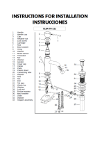
INSTALLATION DU ROBINET (Fig.1)
Introduire la tige filetée (2) et les tuyaux d’alimentation (3)
dans le corps du robinet (1). Insérez l’embase (4), l’o-ring
(5) et introduire le robinet dans le trou du lavabo. Verifier
la position de l’o-ring (5). Introduire le joint façonné (8)
et la bride (9) sur la tige filetée (6). Fermer le robinet avec
l'écrou (10). Connecter les lîres flexibles (7): le tuyau de
gauche avec la distribution de l’eau chaude et le tuyau de
droite avec la distribution de l’eau froide. Ouvrir l’eau et
vérifier le correct fonctionnement du mitigeur et la parfaite
tenue de toutes ses parties.
MONTAGE DU VIDAGE (Fig.2)
(seulement pour l’article 211LL)
Introduire la bonde vidage (13) avec le joint conique (12)
dans le trou du vidage (si est nécessaire utiliser du silicone
entre céramique et le bonde vidage), introduire le joint (14),
la bride (15) et fermer utilisant l’écrou (16). Visser le canot
(18) à la bonde vidage (13) interposant le joint (17).
Positionner la tirette de commande (19), positionner l’élément
(21) comme indiqué dans la figure, fermer avec la calotte
(22). Introduire la tirette de commande tu vidage (2) avec
le pommeau (1) dans le corps du robinet, la connecter à la
tige du vidage avec le joint (20) et régler la course du clapet
(11).
MAINTENANCE ET CONSEILS PRATIQUES-TECHNIQUES
REMPLACEMENT DE LA CARTOUCHE
(fermer l’installation de l’eau) (Fig.3)
Enlever la pastille (1), dévisser la vis (2) et enlever la manette
(3). Dévisser le capuchon (4), l'embout (5) avec l'oring (6)
et démonter la cartouche (7). Introduire la nouvelle cartouche
dans le corps du robinet et remonter en procédant en sens
VESSEL FILLER
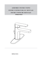
BATHROOM FAUCET
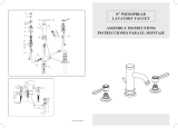
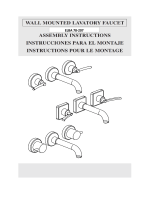
ASSEMBLY INSTRUCTIONS
INSTRUCCIONES PARA EL MONTAJE
INSTRUCTIONS POUR LE MONTAGE
XXXXXXXXXXXX
VPC1102131714
F
Alimentation Recommandée Maximum Minimum
Température eau chaude 65 C° (~150F) 80 C° (~175F) 15 C° (~60F)
Pression dynamique 3 BAR (~45PSI) 5 BAR (~75PSI) 0.5 BAR (~7PSI)
MAINTENANCE DES SURFACES
Pendant le nettoyage, la surface du robinet doit être froide
(la chaleur augmente le risque d’usure de la surface).
S’assurer que les produits pour le nettoyage ne contiennet
pas de produits acides ou abrasifs. Il faut nettoyer le robi-
net tous les jours avec un chiffon doux. Eviter pailles de fer
ou éponges abrasives. Après le nettoyage, enlever les resi-
dus de détergent avec de l’eau froide. Dommages aux robi-
nets causés par un nettoyage pas approprié sont exclus de
notre garantie.
inverse; s’assurer de bien nettoyer les surfaces où agissent
les joints. Serrer l’embase (4) de façon qu’on puisse garantir
l’étanchéité et en même temps un mouvement souple de la
manette.
ASSEMBLY INSTRUCTIONS
If operating pressures exceed 5 BAR (~75 PSI), the use of
a pressure reducer is recommended. Before proceeding
with the assembling, we advise to clean the hot and cold
water tubes, in order to avoid that build-up of dirt could
compromise the functioning of the faucet.
INSTALLATION OF THE FAUCET (Fig.1)
Assemble the threaded pins (2) and the supply tubes (3)
on the faucet body (1). Place the extension tube (3), the
base ring (4) and the o-ring (5), then insert the faucet in
the hole of the sanitary. Verify the correct position of the o-
ring (5). Slip the C-washer (8) and the flange (9) in the
threaded pin (6), then fix the faucet with the nuts (10).
Connect the supply tubes (7): the left one to the hot water
supply and the right one to the cold water supply. Open the
water supply and verify both the correct functioning of the
faucet and the sealing of all the parts.
MOUNTING THE DRAIN (Fig.2) (only for article 211LL)
Insert the Insert the drain (12) with the tapered seal (13) in
the waste hole (if necessary use sealant between drain and
ceramic), then fix using the nut (16) placing washer (14)
and flange (15) in between. Screw the vertical sleeve to the
waste body (18) and all this to the drain (13), placing the
washer (17) in between. Place the horizontal rod (19)
positioning the round piece (21) as shown in the figure,
then fix with the nut (22). Insert the control rod (2) with the
knob (1) in the faucet body, connect it to the waste rod with
the clamp (11) and then regulate the run of the drain plug
(14).
MAINTENANCE AND TECHNICAL-PRACTICAL SUGGE-
STIONS
- REPLACEMENT OF THE CARTRIDGE
(close the waterworks) (Fig.3)
Unscrew the grub screw (2), take out the lever (3), unscrew the
cap (4) and the locking nut (5), then take out the cartridge
(7). Mount it on the new cartridge. To assemble proceed
in reverse order, mind to clean the surfaces in contact
with the sealing washers. Close the nut (5) in such a way
to grant the sealing and in the meantime to allow that the
handle turns smoothly.
MAINTENANCE OF THE SURFACES
During the cleaning, the surface of the faucet has to be
cold (as hot speeds up the wearing out of the surface).
Make sure that cleaning products do not contain acids or
corrosive substances. The faucet has to be daily dried with
a soft cloth. Avoid steel wool, abrasive sponges or similar.
INSTRUCCIONES PARA EL MONTAJE
En caso de presiones de ejercicio superiores a 5 BAR (~75
PSI), se aconseja el uso de un reductor de presión. Antes
de efectuar el montaje, se aconseja vaciar las tuberías del
agua caliente y fría para evitar que suciedad y pequeñas
impurezas comprometan el funcionamiento del grifo.
INSTALACIÓN DEL GRIFO (Fig.1)
Instalar los pernos roscados (2) y los tubos de alimenta-
ción (3) en el cuerpo del grifo (1). Introducir el caño pro-
longador (3), el disco de asiento (4) y el o-ring (5) e intro-
ducir el grifo en el agujero del lavamanos. Controlar la
posición del o-ring (5). Ensartar la guarnición moldeada
(8) y la brida (9) en los pernos roscados (6). Fijar el grifo
con los tirantes (11). Conectar los flexibles
de alimenta-
ción (7): el izquierdo con el suministro del agua caliente y
el derecho con el suministro del agua fría. Abrir el sumini-
stro de agua y verificar el correcto funcionamiento del grifo
y el cierre de todas sus partes.
MONTAJE DEL DESAGÜE (Fig.2) (solo por artículo 211LL)
Introducir la pila del desagüe (12) dotada de guarnición
cónica (13) en el agujero de descarga (si es necesario,
introducir silicona entre cerámica y pila de desagüe),
poner la guarnición (16) y la brida (14) y fijar medio de la
tuerca (15). Enroscar el manguito al cuerpo de desagüe (18)
y éstos juntos a la pila de desagüe (13), poniendo la guarnición
(17) en el medio. Posicionar el asta horizontal de mando
(19), posicionando el elemento (21) de la manera ilustrada
en la figura, por fin fijar todo medio del casquete (22).
Introducir en el cuerpo del grifo el asta de mando del desagüe
(2) dotada de pomo (1) y conectarla al asta de desagüe medio
de la abrazadera (11). Por fin regular la carrera del tapón (14).
MANUTENCION Y CONSEJOS TECNICO-PRATICOS
SUSTITUCION DEL CARTUCHO
(cerrar l’instalación hídrica) (Fig.3)
Destornillar la palanca de mando (2), sacar la manilla (2),
destornillar el capuchón (4) y la virola de apriete (5), luego
sacar el cartucho (7). Introducir el cartucho y montar todo
procediendo en el sentido inverso, cerciorándose de limpiar
las superficies en contacto con las guarniciones de retención.
Enroscar la virola (4) para garantizar el cierre y permitir
un movimiento suave de la manilla.
UK
Supply Suggested Maximum Minimum
Hot water temperature 65 C° (~150F) 80 C° (~175F) 15 C° (~60F)
Operating pressure 3 BAR (~45PSI) 5 BAR (~75PSI) 0.5 BAR (~7PSI)
ES
Alimentación Aconsejada Máxima Minima
Temperatura agua caliente 65 C° (~150F) 80 C° (~175F) 15 C° (~60F)
Presión de ejercicio 3 BAR (~45PSI) 5 BAR (~75PSI) 0.5 BAR (~7PSI)
Fig.1
Fig.3
Fig.2
Soon after cleaning, wash away the residue of cleaning
lotions with cold water. Damages to faucets following from
a not appropriate treatment, are unsecured.
MANUTENCION DE LAS SUPERFICES
Cuando se limpia el grifo, la superficie tiene que ser fría (el
calor acelera el deterioramiento de la superficie).
Cerciorarse que los productos para la limpieza no tengan
ácidos o sustancias corrosivas. El grifo tiene que ser lim-
piado cada día con un trapo suave. No utilizar esponjas
abrasivas o semejantes. Limpiar con agua fría los residuos
de detergente. Daños a grifos como consecuencia de un
tratamiento poco apropiado, están escluidos de nuestra
garancía.
  • Page 1 1
  • Page 2 2

LaToscana 84CR205LLR Installation guide

Category
Sanitary ware
Type
Installation guide

LaToscana 84CR205LLR is a bathroom faucet with features designed to make your bathroom experience more enjoyable.

The faucet has a single lever that controls both the water temperature and flow rate, making it easy to find the perfect combination for your needs. The faucet also features a ceramic cartridge that ensures a smooth and drip-free operation.

The faucet is constructed from durable brass and has a polished chrome finish that will resist corrosion and tarnishing. The faucet is also easy to install, with all the necessary hardware included.

Here are some of the benefits of using the LaToscana 84CR205LLR bathroom faucet:

Ask a question and I''ll find the answer in the document

Finding information in a document is now easier with AI