Page is loading ...

HART
®
Installation and Operating
Manual for Eclipse
®
Model 700
Software Version 1.x
Guided Wave Radar
Level Transmitter

BE 57-660 Eclipse Model 700 Guided Wave Radar Transmitter
Read this Manual Before Installing
This manual provides information on the Eclipse
®
Model 700 transmitter. It is important that all instruc-
tions are read carefully and followed in sequence. The
QuickStart Installation instructions are a brief guide to
the sequence of steps for experienced technicians to fol-
low when installing the equipment. Detailed instruc-
tions are included in the Complete Installation section of
this manual.
Conventions Used in this Manual
Certain conventions are used in this manual to convey
specific types of information. General technical materi-
al, support data, and safety information are presented in
narrative form. The following styles are used for notes,
cautions, and warnings.
NOTES
Notes contain information that augments or clarifies
an operating step. Notes do not normally contain
actions. They follow the procedural steps to which
they refer.
Cautions
Cautions alert the technician to special conditions
that could injure personnel, damage equipment, or
reduce a component’s mechanical integrity. Cautions
are also used to alert the technician to unsafe prac-
tices or the need for special protective equipment or
specific materials. In this manual, a caution box indi-
cates a potentially hazardous situation which, if not
avoided, may result in minor or moderate injury.
WARNINGS
Warnings identify potentially dangerous situations
or serious hazards. In this manual, a warning indi-
cates an imminently hazardous situation which, if
not avoided, could result in serious injury or death.
Safety Messages
The ECLIPSE system is designed for use in Category
II, Pollution Degree 2 installations. Follow all standard
industry procedures for servicing electrical and com-
puter equipment when working with or around high
voltage. Always shut off the power supply before touch-
ing any components. Although high voltage is not pre-
sent in this system, it may be present in other systems.
Electrical components are sensitive to electrostatic dis-
charge. To prevent equipment damage, observe safety pro-
cedures when working with electrostatic sensitive compo-
nents.
This device complies with Part 15 of the FCC rules.
Operation is subject to the following two conditions:
(1) This device may not cause harmful interference, and
(2) This device must accept any interference received,
including interference that may cause undesired operation.
WARNING! Explosion hazard. Do not connect or dis-
connect unless power has been switched off and/or the
area is known to be non-hazardous.
Low Voltage Directive
For use in Installations Category II, Pollution Degree 2.
If equipment is used in a manner not specified by the
manufacturer, protection provided by equipment may
be impaired.
Notice of Copyright and Limitations
Magnetrol
®
& Magnetrol
®
logotype and Eclipse
®
are registered trademarks of Magnetrol
®
International,
Incorporated.
Copyright © 2020 Magnetrol
®
International,
Incorporated. All rights reserved.
MAGNETROL reserves the right to make changes to
the product described in this manual at any time with-
out notice. MAGNETROL makes no warranty with
respect to the accuracy of the information in this man-
ual.
Warranty
All MAGNETROL electronic level and flow controls
are warranted free of defects in materials or workman-
ship for eighteen months from the date of original fac-
tory shipment. If returned within the warranty period;
and, upon factory inspection of the control, the cause
of the claim is determined to be covered under the war-
ranty; then, MAGNETROL will repair or replace the
control at no cost to the purchaser (or owner) other than
transportation.
MAGNETROL shall not be liable for misapplication,
labor claims, direct or consequential damage or expense
arising from the installation or use of equipment.
There
are no other warranties expressed or implied, except spe-
cial written warranties covering some MAGNETROL
products.
Quality Assurance
The quality assurance system in place at MAGNETROL
guarantees the highest level of quality throughout the
company. MAGNETROL is committed to providing
full customer satisfaction both in quality products and
quality service.
The MAGNETROL quality assurance system is regis-
tered to ISO 9001 affirming its commitment to known
international quality standards providing the strongest
assurance of product/service quality available.

Table of Contents
1.0 QuickStart Installation
1.1 Getting Started..........................................................5
1.1.1 Equipment and Tools .....................................5
1.1.2 Configuration Information.............................6
1.2 QuickStart Mounting................................................7
1.2.1 Transmitter/Probe ..........................................7
1.3 QuickStart Wiring ....................................................8
1.4 QuickStart Configuration .........................................8
1.4.1 QuickStart Menu Options ...........................10
1.4.1.1 QuickStart Numerical Data Entry.........11
2.0 Complete Installation
2.1 Unpacking ..............................................................12
2.2 Electrostatic Discharge (ESD)
Handling Procedure ................................................12
2.3 Before You Begin.....................................................13
2.3.1 Site Preparation ............................................13
2.3.2 Equipment and Tools ...................................13
2.3.3 Operational Considerations..........................13
2.4 Mounting................................................................14
2.4.1 Installing a Coaxial Probe
(Models 7zP and 7zT)..................................14
2.4.1.1 To install a coaxial probe .......................15
2.4.2 Installing a Single Rod Probe
Rigid Models 7zF
Flexible Models 7z1......................................15
2.4.2.1 To install a rigid single rod probe ..........16
2.4.2.2 To install a flexible single rod probe ......16
2.5 Wiring ....................................................................17
2.5.1 General Purpose or Non-Incendive
(CI I, Div 2) ..................................................17
2.5.2 Intrinsically Safe...........................................18
2.6 Configuration .........................................................19
2.6.1 Bench Configuration....................................19
2.6.2 Menu Traversal and Data Entry....................20
2.6.2.1 Navigating the Menu.............................20
2.6.2.2 Data Selection .......................................20
2.6.2.3 Entering Numeric Data Using
Digit Entry............................................21
2.6.2.4 Entering Numeric Data
Using Increment/Decrement .................21
2.6.2.5 Entering Character Data........................22
2.6.3 Password Protection .....................................22
2.6.4 Model 700 Menu: Step-By-Step Procedure ..23
2.6.5 Model 700 Configuration Menu —
Device Setup ................................................25
2.7 Configuration Using HART
®
..................................31
2.7.1 Connections .................................................31
2.7.2 HART Communicator Display ....................31
2.7.3 HART Revision Table ..................................31
2.7.4 HART Menu — Model 700 ........................31
3.0 Reference Information
3.1 Transmitter Description ..........................................36
3.2 Theory of Operation...............................................36
3.2.1 Guided Wave Radar .....................................36
3.2.2 Time Domain Reflectometry (TDR)............36
3.2.3 Equivalent Time Sampling (ETS).................37
3.2.4 Interface Detection.......................................37
3.2.5 Overfill Capability........................................39
3.3 Troubleshooting and Diagnostics ............................39
3.3.1 Diagnostics (Namur NE 107) ......................40
3.3.2 Diagnostic Indication Simulation.................42
3.3.3 Diagnostic Indication Table..........................42
3.3.4 Diagnostic Help ...........................................45
3.3.5 Troubleshooting Application Issues ..............46
3.3.5.1 Model 700 (Single Rod Probe) ..............47
Eclipse
®
Model 700 Guided Wave Radar Transmitter
3
BE 57-660 Eclipse Model 700 Guided Wave Radar Transmitter

3.4 Configuration Information .....................................49
3.4.1 Level Offset Description...............................49
3.4.2 End-of-Probe Analysis ..................................50
3.4.3 Echo Rejection .............................................51
3.4.4 Volumetric Capability ..................................51
3.4.4.1 Configuration using built-in
Vessel Types ...........................................51
3.4.4.2 Configuration using Custom Table........53
3.4.5 Open Channel Flow Capability....................54
3.4.5.1 Configuration using Flume/Weir
Equations ..............................................55
3.4.5.2 Configuration using Generic
Equation................................................56
3.4.5.3 Configuration using Custom
Table......................................................57
3.4.6 Reset Function .............................................58
3.4.7 Additional Diagnostic/Troubleshooting
Capabilities ................................................58
3.4.7.1 Event History ........................................58
3.4.7.2 Context-sensitive Help ..........................58
3.4.7.3 Trend Data ............................................58
3.5 Agency Approvals....................................................59
3.5.1 Special Conditions of Use ............................59
3.5.2 Agency Specifications — FM/CSA
Intrinsically Safe Installation ........................60
3.6 Specifications ..........................................................61
3.6.1 Functional/Physical ......................................61
3.6.2 O-ring (Seal) Selection Chart .......................63
3.6.3 Probe Selection Guide..................................64
3.6.4 Probe Specifications......................................65
3.6.5 Physical Specifications — Transmitter..........66
3.6.6 Physical Specifications — Coaxial Probes.....67
3.6.7 Physical Specifications —
Single Rod Probes ........................................67
3.6.8 Power Supply Requirements.........................68
3.6.8.1 Safe Operating Area...............................68
3.6.8.2 Supply Voltage.......................................68
3.7 Model Number .......................................................69
3.7.1 Transmitter...................................................69
3.7.2 Basic Coaxial Probe......................................70
3.7.3 Enlarged Coaxial Probe ................................72
3.7.4 Single Rod Rigid Probe ................................74
3.7.5 Single Cable Flexible Probe ..........................76
3.9 Replacement Parts...................................................78
4.0 Advanced Configuration/Troubleshooting Techniques
4.1 End-of-Probe Analysis (EOPA) ................................80
4.1.1 Enable EOPA using PACTware .....................80
4.1.2 Enable EOPA using keyboard/LCD...............81
4.2 Sloped Threshold .....................................................82
4.3 Echo Rejection .........................................................84
4.4 Buildup Detection....................................................87
4.4.1 Buildup Detection Setup using PACTware....88
4.4.2 Buildup Detection Setup using the Keypad ...89
4
BE 57-660 Eclipse Model 700 Guided Wave Radar Transmitter

5
BE 57-660 Eclipse Model 700 Guided Wave Radar Transmitter
1.0 QuickStart Installation
The QuickStart Installation procedures provide an overview
of the key steps required for mounting, wiring, and config-
uring the ECLIPSE Model 700 Guided Wave Radar level
transmitter. These procedures are intended for more experi-
enced installers of ECLIPSE transmitters (or other electron-
ic level measurement instruments).
Section 2.0, Complete Installation, offers more detailed
installation instructions for the first time user.
WARNING: Overfill-capable probes such as the Model 7zP or 7zT
should be used for any Safety Shutdown/Overfill appli-
cations.
The Model 700 transmitter, when used with an overfill
coaxial probe, is capable of measuring true liquid level all
the way up to the face of the flange or NPT connection.
This is a very unique advantage as compared to other
Guided Wave Radar (GWR) devices that may infer level
at the top of the probe when signals are lost or uncertain.
Refer to Section 3.2.5 for additional information on over-
fill capability.
Depending on the probe type, all other ECLIPSE probes
should be installed so the maximum overfill level is a
minimum of 150–300 mm (6"–12") below the flange or
NPT connection. This may include utilizing a nozzle or
spool piece to raise the probe. Consult factory to ensure
proper installation and operation.
1.1 Getting Started
Have the proper equipment, tools, and information
available before beginning the QuickStart Installation
procedures.
1.1.1 Equipment and Tools
• Open-end wrenches (or adjustable wrench) to fit the process
connection size and type.
•
Coaxial probe: 38 mm (1 1/2")
•
Single rod probe: 47 mm (1 7/8")
• Flat-blade screwdriver
• Cable cutter and 3/32" hex wrench
(for flexible cable probes only)
• Digital multimeter (DMM)
• 24 VDC power supply, 23 mA minimum

1.1.2 Configuration Information
To utilize the QuickStart menu available on the
ECLIPSE Model 700, some key information is required
for configuration.
Gather the information and complete the following operating
parameters table before beginning configuration.
NOTES: The QuickStart menu is available for Level Only applications.
1. Refer to Section 2.6.5 for configuration menus for Interface,
Volume or Flow applications.
2. These configuration steps are not necessary if the transmitter
was pre-configured prior to shipment.
Display Question Answer
Level Units What units of measurement will be used?
(inches, millimeters, centimeters, feet
or meters) _____________
Probe Model What probe model is listed on the
model information?
(first three digits of probe model number) _____________
Probe Mount Is the probe mounted NPT, BSP,
or flange? (Refer to probe model.) _____________
Probe Length What probe length is listed on the
probe model information? (last three
digits of the probe model number) _____________
Level Offset The desired level reading when the
liquid is at the tip of the probe. (Refer
to Section 3.4 for more information.) _____________
Dielectric Range What is the dielectric constant range
of the process medium? _____________
4.0 mA What is the 0 % reference point for the
Set Point 4.0 mA value? _____________
20.0 mA What is the 100 % reference point for
Set Point the 20.0 mA value?
(Ensure that this value is outside of the
Blocking Distance when utilizing non-
overfill-capable probes.) _____________
Failure Alarm What output current is desired when
a Failure Indicator is present? _____________
6
BE 57-660 Eclipse Model 700 Guided Wave Radar Transmitter

7
BE 57-660 Eclipse Model 700 Guided Wave Radar Transmitter
1.2 QuickStart Mounting
Ensure that the configuration style and process connection
size/type of the ECLIPSE transmitter and probe matches
the requirements of the installation before continuing with
the QuickStart installation.
NOTE: To avoid moisture ingress in the housing, covers should be fully
tightened at all times. For same reason, conduit entries should
be properly sealed.
1.2.1 Transmitter/Probe
The Model 700 transmitter and probe are shipped as a set
and should not be separated in the field.
1. Carefully place the probe into the vessel. Align the probe
process connection with the threaded or flanged mounting
on the vessel.
2. Tighten the hex nut of the probe process connection or
flange bolts, ensuring the transmitter is in an optimal posi-
tion for viewing and configuration.
¿
¡

1.3 QuickStart Wiring
WARNING! Possible explosion hazard. Do not connect or discon-
nect equipment unless power has been switched off and
the area is known to be non-hazardous.
NOTE: Ensure that the electrical wiring to the ECLIPSE Model 700
transmitter is complete and in compliance with all local regula-
tions and codes.
1. Remove the cover of the Model 700 transmitter.
2. Using the grip edge at 3 o’clock and 9 o’clock on the LCD
module shown at left, carefully remove the LCD module
from the transmitter. (Note that this module is conveniently
tethered to the device.)
3. Attach a conduit fitting and mount the conduit plug in the
spare opening. Pull power supply wire through the fitting.
4. If present, connect cable shield to an earth ground at the
power supply.
5. Connect an earth ground to the green ground screw (Not
shown in illustration).
6. Connect the positive supply wire to the (+) terminal and the
negative supply wire to the (-) terminal.
7. Align the LCD assembly in the connector slot and re-insert
the LCD assembly; replace and tighten the cover.
1.4 QuickStart Configuration
If requested, the ECLIPSE Model 700 transmitter is
shipped fully pre-configured for the application and can be
installed immediately. Otherwise it is shipped configured
with default values from the factory and can be easily
reconfigured in the shop.
The minimum configuration instructions required for using
the QuickStart menu follow. Use the information from the
operating parameters table in Section 1.1.2 to proceed with
the configuration.
The QuickStart menu offers a very simple two screen
overview showing the basic parameters required for typical
“Level Only” operation.
1. Apply power to the transmitter.
The graphic LCD display can be programmed to change
every 2 seconds to show pertinent Measured Values on the
Home Screen. For example: Level, %Output, and Loop
current can all be displayed on a rotating set of screens.
The LCD can also be programmed to always show just one
of the Measured Variables at all times. For example: Level
can be continuously displayed on the screen.
NOTE: A small transition zone (0-300 mm)
(0–12") may exist at the top and
bottom of certain probes.
Back
Grip
here
LCD Connector Slot
Grip
here
Enter
8
BE 57-660 Eclipse Model 700 Guided Wave Radar Transmitter
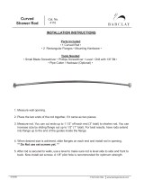
Probe Mount
20 mA
(100 % Point)
Probe Model
Dielectric
of Medium
4 mA Level
(0 % - point)
Level Offset
Probe Length
In or Cm

2. The 4-button directional keypad offers multiple forms of
functionality for menu navigation and data entry. (See
Section 2.6 for complete explanation.)
UP moves up through the menu or increases a displayed
value.
DOWN moves down through the menu or decreases a
displayed value.
BACK exits a branch of the menu or exits without
accepting entered value.
ENTER enters a branch of the menu or accepts a
displayed entry.
NOTE: Holding down ENTER when any menu or parameter is high-
lighted will show help text in reference to that item.
The default User Password = 0. (If a password is requested,
enter it at that time.)
The following configuration entries are the minimum
required for a QuickStart configuration. Refer to figures at
left.
3. Press any key at the Home Screen to access the Main Menu.
4. Press ENTER with the DEVICE SETUP menu item
highlighted.
5. Press ENTER with the QUICKSTART menu item
highlighted.
The QuickStart shows the basic parameters, with the
present value of the highlighted parameter shown at the
bottom of the screen.
One can now quickly and easily scroll through the
QuickStart configuration items, changing those parameters
as required:
• Scroll to the parameter to be changed.
• Press ENTER at the highlighted parameter.
• Scroll to the desired option, then press ENTER.
• Scroll to next parameter or press BACK when
finished to exit the QuickStart menu.
Section 1.4.1 lists and describes the nine parameters in the
QuickStart menu.
6. After making all of the necessary changes in the QuickStart
menu, press the BACK button three times to return to the
Home Screen.
7. The QuickStart configuration is complete. If properly con-
figured, the Model 700 transmitter is now measuring level
and is ready for service.
▲
▲
▲
▲
▲ ▲
▲
▲
▲
STEP 4
STEP 5
STEP 6
9
BE 57-660 Eclipse Model 700 Guided Wave Radar Transmitter

Level Units Select the Units of measurement for the level readout:
• Inches
• Feet
• Millimeters
• Centimeters
• Meters
Probe Model Select the Probe Model to be used with Model 700:
• 7zF Single Rod
• 7zP Coaxial High Pressure
• 7zT Coaxial Standard
• 7z1 Single Flexible Standard
Probe Mount Select the type of Probe Mounting to the vessel:
• NPT (National Pipe Thread)
• BSP (British Standard Pipe)
• Flange (ASME or EN)
Probe Length Enter the exact Probe Length as printed on the probe nameplate. Probe Length is
shown as the last three digits of the Probe Model number. Range is 30 cm to 30 meters
(12 inches to 100 feet) probe dependent. Refer to Section 1.4.1.1.
Level Offset Enter the desired level reading when the liquid is at the end of the probe. Range is -762
cm to 22 meters (-25 feet to 75 feet). Refer to Section 3.4 for further information. (With
default Level Offset = 0, all measurements are referenced from the bottom of the probe.)
Dielectric Range Enter the Dielectric Range for the material to be measured.
• Below 1.7 (Light hydrocarbons like Propane and Butane)
• 1.7 to 3.0 (Most typical hydrocarbons)
• 3.0 to 10 (Varying dielectric, for example: mixing tanks)
• 10 (Water-based media)
HART Only
4 mA Set Point
(LRV)
Enter the level value (0 %-point) for the 4 mA point. Lower Range Value (LRV).
Refer to Section 1.4.1.1.
20 mA Set Point
(URV)
Enter the level value (100 %-point) for the 20 mA point. Upper Range Value (URV).
Refer to Section 1.4.1.1.
Failure Alarm
Enter the desired output state when a Failure Indicator is active.
• 22 mA
• 3.6 mA
• Hold (Hold last value is not recommended, unless troubleshooting)
1.4.1 QuickStart Menu Options
10
BE 57-660 Eclipse Model 700 Guided Wave Radar Transmitter

11
BE 57-660 Eclipse Model 700 Guided Wave Radar Transmitter
1.4.1.1 QuickStart Numerical Data Entry
To make numerical entry changes to Probe Length and
Level Offset:
UP moves up to the next highest digit (0,1,2,3,....,9 or
the decimal point).
If held down the digits scroll until the push button is
released.
DOWN moves up to the next lowest digit (0,1,2,3,....,9
or the decimal point). If held down the digits scroll until
the push button is released.
BACK moves the cursor to the left and deletes a digit.
If the cursor is already at the leftmost position, then the
screen is exited without changing the previously saved
value.
ENTER moves the cursor to the right. If the cursor is
located at a blank character position, the new value is
saved.
Scrolling further DOWN in the QuickStart menu results in
the remaining parameters appearing one by one, with the
present highlighted value shown at the bottom of the
screen.
BACK returns to the previous menu without changing
the original value, which is immediately redisplayed.
ENTER accepts the displayed value and returns to the
previous menu.
Negative values can be entered by highlighting the “+” sign
shown prior to the number, then pressing UP to change it
to show “-”.
▲
▲
▲
▲▲
▲

2.0 Complete Installation
This section provides detailed procedures for properly
installing, wiring, and configuring the ECLIPSE Model 700
Guided Wave Radar Level Transmitter.
2.1 Unpacking
Unpack the instrument carefully. Make sure all components
have been removed from the packing material. Check all
contents against the packing slip and report any discrepan-
cies to the factory.
Before proceeding with the installation,
• Inspect all components for damage. Report any damage to
the carrier within 24 hours.
• Make sure the nameplate model number on the transmitter
agrees with the packing slip and purchase order.
• Record the model and serial numbers for future reference
when ordering parts.
Model Number
Serial Number
NOTE: To avoid moisture ingress in the housing, covers should be fully
tightened at all times. For same reason, conduit entries should
be properly sealed.
2.2 Electrostatic Discharge (ESD)
Handling Procedure
MAGNETROL electronic instruments are manufactured to
the highest quality standards. These instruments use elec-
tronic components that may be damaged by static electricity
present in most work environments.
The following steps are recommended to reduce the risk of
component failure due to electrostatic discharge.
• Ship and store circuit boards in anti-static bags. If an anti-
static bag is not available, wrap the board in aluminum
foil. Do not place boards on foam packing materials.
12
BE 57-660 Eclipse Model 700 Guided Wave Radar Transmitter

13
BE 57-660 Eclipse Model 700 Guided Wave Radar Transmitter
• Use a grounding wrist strap when installing and removing
circuit boards. A grounded workstation is recommended.
• Handle circuit boards only by the edges. Do not touch
components or connector pins.
• Make sure that all electrical connections are completely
made and none are partial or floating. Ground all equip-
ment to a good, earth ground.
2.3 Before You Begin
2.3.1 Site Preparation
Each ECLIPSE Model 700 transmitter is built to match the
physical specifications of the required installation. Ensure
that the probe process connection is correct for the threaded
or flanged mounting on the vessel where the transmitter will
be placed. See Mounting, Section 2.4.
Ensure that all local, state, and federal regulations and
guidelines are observed. See Wiring, Section 2.5.
Ensure that the wiring between the power supply and
ECLIPSE transmitter is complete and correct for the type
of installation. See Specifications, Section 3.6.
2.3.2 Equipment and Tools
No special equipment or tools are required to install the
ECLIPSE transmitter. The following items are recommended:
• Open-end wrenches (or adjustable wrench) to fit the process
connection size and type.
•
Coaxial probe: 38 mm (1 1/2")
•
Single Rod probe: 47 mm (1 7/8")
A torque wrench is highly desirable.
• Flat-blade screwdriver
• Cable cutter and 3/32" hex wrench (for flexible cable probes
only)
• Digital multimeter (DMM)
• 24 VDC power supply, 23 mA minimum
2.3.3 Operational Considerations
Operating specifications vary based on probe model
number. See Specifications, Section 3.6.

2.4 Mounting
An ECLIPSE Model 700 GWR probe can be mounted on
to a tank using a variety of process connections. Generally,
either a threaded or flanged connection is used. For infor-
mation about the sizes and types of connections available,
see Probe Model Numbers, Section 3.7.2.
NOTE: Do not place insulating material around any part of the ECLIPSE
Model 700 transmitter as this may cause excessive heat buildup.
Ensure that all mounting connections are properly in place
on the tank before installing the probe.
WARNING! Overfill-capable probes such as the Model 7zP or 7zT
should be used for any Safety Shutdown/Overfill appli-
cations.
The Model 700 transmitter, when used with an overfill
coaxial probe, is capable of measuring true liquid level to
within specification all the way up to the face of the
flange or NPT connection. This is a very unique advan-
tage as compared to other Guided Wave Radar (GWR)
devices that may infer level at the top of the probe when
signals are lost or uncertain. Refer to Section 3.2.6 for
additional information on overfill capability.
All other ECLIPSE probes should be installed so the
maximum overfill level is a minimum of 150 mm (6")
below the flange or NPT connection. This may include
utilizing a nozzle or spool piece to raise the probe.
Consult factory to ensure proper installation and operation.
WARNING! Do not disassemble probe when in service and under
pressure.
NOTE: Model 7zP high pressure probe (containing a glass ceramic
alloy process seal) should be handled with extra care. Handle
this probe only by the flange or NPT connection. If supplied,
remove transport hardware as shown at left prior to installation.
2.4.1 Installing a Coaxial Probe
(Models 7zP and 7zT)
Before installing, ensure that:
• Probe has adequate room for installation and has unob-
structed entry to the bottom of the vessel.
• Process temperature, pressure, dielectric, and viscosity are
within the probe specifications for the installation. See
Specifications, Section 3.6.
14
BE 57-660 Eclipse Model 700 Guided Wave Radar Transmitter
Remove transport screws
and/or cable ties, if applicable

15
BE 57-660 Eclipse Model 700 Guided Wave Radar Transmitter
2.4.1.1 To install a coaxial probe:
1. Ensure that the process connection is the correct threaded
or flanged mounting.
2. Carefully place the probe into the vessel. Properly align the
gasket on flanged installations.
3. Align the probe process connection with the threaded or
flanged mounting on the vessel.
4. For threaded connections, tighten the hex nut of the probe
process connection. For flanged connections, tighten flange
bolts.
2.4.2 Installing a Single Rod Probe
Rigid Models 7zF
Flexible Models 7z1
Before installing, ensure that the:
• Probe has adequate room for installation and has unob-
structed entry to the bottom of the vessel.
• Process temperature, pressure, dielectric, and viscosity are
within the probe specifications for the installation. See
Specifications, Section 3.6.
NOTE: If using a removable single rod, ensure that all pieces are
assembled and connected before installation.
1. Ensure that the nozzle does not restrict performance by
ensuring the following (refer to figure at left):
• Nozzle is > 50 mm (2") diameter.
• Ratio of Diameter: Length (A:B) is 1:1 or greater; any ratio
<1:1 (e.g., a 50 mm x 152 mm, 2"¥ 6" nozzle = 1:3) may
require a Blocking Distance and/or DIELECTRIC
RANGE adjustment.
2. No pipe reducers (restrictions) are used.
3. Probe is kept away from conductive objects to ensure prop-
er performance.
• See Probe Clearance Table below. A lower gain (increase in
DIELECTRIC RANGE setting) may be necessary to
ignore certain objects
• This table is only a recommendation. These distances can
be improved by optimizing the transmitter configuration
with PACTware
™
.
②
①
④
③
A
B
Distance
to Probe
Acceptable Objects
<15 cm (6")
Continuous, smooth, parallel conductive surface, for example a metal
tank wall; important that probe does not touch wall
>15 cm (6") <25 mm (1") diameter pipe and beams, ladder rungs
>30 cm (12") <75 mm (3") diameter pipe and beams, concrete walls
>46 cm (18") All remaining objects

16
BE 57-660 Eclipse Model 700 Guided Wave Radar Transmitter
2.4.2.1 To install a rigid single rod probe:
1. Ensure that the process connection is at least 1" NPT or is a
flanged mounting.
2. Carefully place the probe into the vessel. Align the gasket
on flanged installations.
3. Align the probe process connection with the threaded or
flanged mounting on the vessel.
4. For threaded connections, tighten the hex nut of the probe
process connection. For flanged connections, tighten flange
bolts.
5. When mounted directly into vessels, the probe can be stabi-
lized by placing the tip of the probe into a non-metallic cup
or bracket at the bottom of the probe.
A bottom spacer option is offered for mounting into a
metallic cup or bracket or for centering within a pipe/cham-
ber. Refer to Replacement Parts, Section 3.8 for additional
information.
2.4.2.2 To install a flexible single rod probe:
1. Make sure the process connection is at least 1" NPT or a
flanged mounting.
2. Carefully place the probe into the vessel. Align the gasket
on flanged installations.
3. Align the probe process connection with the threaded or
flanged mounting on the vessel.
4. For threaded connections, tighten the hex nut of the probe
process connection. For flanged connections, tighten flange
bolts.
5. Probe can be shortened in field:
a. Raise TFE weight (1) exposing securing device (2).
b. Loosen both #10–32 set screws (3) using 3/32" hex
wrench and remove securing device.
c. Cut and remove needed cable (4) length.
d. Reattach securing device and tighten screws.
e. Enter new probe length (in the appropriate units) into
the transmitter.
6. Probe can be attached to the tank bottom using the 13 mm
(0.50") hole provided in the TFE weight. Cable tension
should not exceed 23 Kgs (50 lbs).
➄
➀
➁
➂
➃
1
0.50" (13 mm) Ø
2
3
4
➄
➀
➁
➂
➃
➅
13 mm (0.50 ") Ø

2.5 Wiring
Caution: The ECLIPSE Model 700 transmitter operates at voltages
of 11–36 VDC. Higher voltages will damage the transmitter.
Wiring connections between the power supply and the
ECLIPSE Model 700 transmitter should be made using
18–22 AWG shielded twisted pair instrument cable.
Connections are made to the terminal strip and the
ground connections beneath the LCD module.
The directions for wiring the ECLIPSE transmitter depend
on the application:
• General Purpose
• Intrinsically Safe
• Non-Incendive (Cl I, Div. 2)
WARNING! Explosion hazard. Do not disconnect equipment unless
power has been switched off or the area is known to be
non-hazardous.
2.5.1 General Purpose or Non-Incendive (Cl I, Div. 2)
A general purpose installation does not have flammable
media present.
Areas rated Non-Incendive (Cl I, Div. 2) have flammable
media present only under abnormal conditions.
No special electrical connections are required.
To install General Purpose or Non-Incendive wiring:
1. Remove the cover of the Model 700 transmitter.
2. Using the grip edge at 3 o’clock and 9 o’clock on the LCD
module shown at left, carefully remove the LCD module
from the transmitter. (Note that this module is conve-
niently tethered to the device.)
3. Attach a conduit fitting and mount the conduit plug in the
spare opening. Pull power supply wire through the fitting.
4. If present, connect cable shield to an earth ground at the
power supply.
5. Connect an earth ground to the green ground screw (Not
shown in illustration).
6. Connect the positive supply wire to the (+) terminal and
the negative supply wire to the (-) terminal.
7. Align the LCD assembly in the connector slot and re-insert
the LCD assembly; replace and tighten the cover.
Back
Grip
here
LCD Connector Slot
Grip
here
Enter
17
BE 57-660 Eclipse Model 700 Guided Wave Radar Transmitter

2.5.2 Intrinsically Safe
An Intrinsically Safe (IS) installation potentially has flam-
mable media present. An approved IS barrier must be
installed in the non-hazardous (safe) area to limit the avail-
able energy out to the hazardous area.
See Agency Drawing – Intrinsically Safe Installation,
Section 3.5.2.
To install Intrinsically Safe wiring:
1. Remove the cover of the Model 700 transmitter.
2. Using the grip edge at 3 o’clock and 9 o’clock on the LCD
module shown at left, carefully remove the LCD module
from the transmitter. (Note that this module is conve-
niently tethered to the device.)
3. Attach a conduit fitting and mount the conduit plug in
the spare opening. Pull power supply wire through the fit-
ting.
4. If present, connect cable shield to an earth ground at the
power supply.
5. Connect an earth ground to the green ground screw (Not
shown in illustration).
6. Connect the positive supply wire to the (+) terminal and
the negative supply wire to the (-) terminal.
7. Align the LCD assembly in the connector slot and re-
insert the LCD assembly; replace and tighten the cover.
Back
Grip
here
LCD Connector Slot
Grip
here
Enter
18
BE 57-660 Eclipse Model 700 Guided Wave Radar Transmitter

19
BE 57-660 Eclipse Model 700 Guided Wave Radar Transmitter
2.6 Configuration
Although the ECLIPSE Model 700 transmitter can be
delivered pre-configured from the factory, it can also be
easily reconfigured in the shop or at the installation using
the local LCD/Keypad or PACTware/DTM. Bench config-
uration provides a convenient and efficient way to set up
the transmitter before going to the tank site to complete
the installation.
Before configuring any transmitter, collect all operating
parameters information (refer to Section 1.1.2).
Apply power to the transmitter and follow the step-by-step
procedures below for the menu-driven transmitter display.
Refer to Sections 2.6.2 and 2.6.4.
Information on configuring the transmitter using a HART
communicator is given in Section 2.7, Configuration
Using HART.
2.6.1 Bench Configuration
The ECLIPSE Model 700 transmitter can be easily config-
ured at a test bench by connecting a standard 24 VDC
power supply directly to the transmitter terminals.
When using a HART communicator for configuration, a
minimum 250-ohm line load resistance is required. Refer
to your HART communicator manual for additional
information.

2.6.2 Menu Traversal and Data Entry
The 4-button directional keypad push buttons offer vari-
ous forms of functionality for navigation and data entry.
The Model 700 user interface is hierarchical in nature,
best described as a tree structure. Each level in the tree
contains one or more items. Items are either menu labels
or parameter names.
• Menu labels are presented in all capital letters
• Parameters are capitalized words
2.6.2.1 Navigating the Menu
UP moves to the previous item in the menu branch.
DOWN moves to the next item in the menu branch.
BACK moves back one level to the previous (higher)
branch item.
ENTER enters into the lower level branch or switches
to the entry mode. Holding the ENTER down on any
highlighted menu name or parameter will show help
text for that item.
2.6.2.2 Data Selection
This method is used for selecting configuration data from
a specific list.
UP and DOWN to navigate the menu and high-
light the item of interest.
ENTER allows modification of that selection.
UP and DOWN to choose new data selection.
ENTER to confirm selection.
Use BACK (Escape) key at any time to abort the proce-
dure and escape to previous branch item.
▲
▲
▲
▲
▲
▲
▲
▲
▲
▲
▲
20
BE 57-660 Eclipse Model 700 Guided Wave Radar Transmitter
/