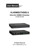
CYP PUV-1230PL-TX User manual

Category
AV extenders
Type
User manual

This manual is also suitable for

Operation Manual
Operation Manual
CH-1529TXPL/RXPL
HDCP 2.2 & HDMI2.0 Extender with OAR / Audio
Insertion
PUV-1230PL-RX
PUV-1230PL-TX
HDCP 2.2 & HDMI2.0 Extender with OAR / Audio
Insertion
SAFETY PRECAUTIONS
Please read all instructions before attempting to unpack, install or
operate this equipment and before connecting the power supply.
Please keep the following in mind as you unpack and install this
equipment:
Always follow basic safety precautions to reduce the risk of fi re,
electrical shock and injury to persons.
To prevent fi re or shock hazard, do not expose the unit to rain,
moisture or install this product near water.
Never spill liquid of any kind on or into this product.
Never push an object of any kind into this product through any
openings or empty slots in the unit, as you may damage parts
inside the unit.
Do not attach the power supply cabling to building surfaces.
Use only the supplied power supply unit (PSU). Do not use the PSU
if it is damaged.
Do not allow anything to rest on the power cabling or allow any
weight to be placed upon it or any person walk on it.
To protect the unit from overheating, do not block any vents or
openings in the unit housing that provide ventilation and allow for
suffi cient space for air to circulate around the unit.
REVISION HISTORY
VERSION NO. DATE DD/MM/YY SUMMARY OF CHANGE
RDV1 08/03/16 Preliminary Release
CONTENTS
1. Introduction ..................................................1
2. Applications .................................................1
3. Package Contents ......................................1
4. System Requirements ..................................2
5. Features ........................................................2
6. Operation Controls and Functions .............3
6.1 Front Panel of Transmitter ..................... 3
6.2 Rear Panel of Transmitter ..................... 4
6.3 Right Side Panel of Transmitter ............ 4
6.4 Front Panel of Receiver ...................... 10
6.5 Rear Panel of Receiver ...................... 11
6.6 IR Cable Pin Assignment..................... 11
6.7 D-Sub 9 Pin Defi nitions ........................ 12
7. Speci cations ............................................13
7.1 CAT5e/6/7 Cable Specifi cation ........ 15
7.2 Timing Support Table .......................... 15
7.3 HDBT Features ..................................... 16
8. Connection and Installation .....................17
9. Acronyms ...................................................18
1
1
1. INTRODUCTION
The HDMI over single CAT5e/6/7 Transmitter and Receiver set is a
great solution to extend uncompressed audio/video and IP data
over a single run of CAT5e/6/7 cable at a distance up to 60 meter.
Multi-control interfaces are available which includes IR, RS-232 and
USB connection. This new extender set complies with advanced
protocols of HDCP2.2 and HDMI 2.0, the HDCP1.4 also supported.
The 6G HDMI video is able to be processed. Except extend 4K2K
data, it features useful audio functions. The “optical audio return”
supports audio transmit back from Receiver to Transmitter. Besides,
the “audio insertion” allows external audio insert to HDMI video such
as background music insertion. The HDBT clock stretch and TMDS re-
clocking are considered. The Receiver (PD) can be powered by the
PoE 48V function of the Transmitter (PSE), allowing for greater fl exibility
to fi t different installation scenarios.
2. APPLICATIONS
48V PoE from Transmitter (PSE) to Receiver (PD)
Household entertainment sharing and control
Lecture room display and control
Showroom display and control
Meeting room presentation and control
Classroom display and control
3. PACKAGE CONTENTS
1 x HDMI over CAT5e/6/7 Transmitter
1 x HDMI over CAT5e/6/7 Receiver
1 x IR Blaster
1 x IR Extender
1 x 48V / 0.83A DC power adapter
1 x Power cable
2 x RS232 terminal block pitch
2 x Audio terminal block
2 x Rack ear Sets
1 x Operation Manual
2
2
4. SYSTEM REQUIREMENTS
Input source equipment such as PS3/Blu-ray player and output HD TV/
display.
5. FEATURES
HDCP 1.4/HDCP 2.2 and HDMI 2.0 compliant
HDMI with 3D, 4K2K support and DVI Compliant
6G HDMI video (3840x2160 YUV444) input is supported
Simultaneous transmission of uncompressed data over a single
CAT5e/6/7 cable up to 60m /196.8 ft at 1080p and 35m/115ft at 4K2K
4Play™ convergence: HDMI, PoE & Control (IR & RS-232)
Supports output resolution up to 4K2K@50/60 _YUV_420
Supports deep color input and output of 8 bits, 10 bits and 12 bits
Supports CEC bypass
Optical audio return supports audio transmit back from receiver to
transmitter
Audio insertion supports external audio insert to HDMI video such as
background music insertion
Supports EDID management PC software with default EDID and
native EDID from display or other sink devices
Supports HDMI DDC bus clock stretch for better compatibility of some
Blu-ray players
Manages TMDS re-clocking and signal re-generation for better signal
Supports standard 48V from Transmitter (PSE) to Receiver (PD)
Easily fi rmware update via USB in fi eld
Ultra-thin wall plate design with friendly installation (The thickness is
16mm only)
Note: 1. The standard 48V PoE function is designed for powering
compatible Receiver units only---non-PoE Receivers will need
their own power supply. Receivers of another brand may not
be compatible.
2. Displaying HDMI 3D and 4K2K contents, equivalent source
signal and HDMI cable are required in order to secure the
quality.
3
3
6. OPERATION CONTROLS AND FUNCTIONS
6.1 Front Panel of Transmitter
DC 48V
POWER
OPT. OUTIR IN 2IR OUT 1SERVICERS-232
TX RX
+
-
AUDIO OUT
UPDATE
L
R
1 2 3 65 7 8 94
1
DC 48V: Plug the 48V DC power supply into the unit. Please do
follow the label on adapter to connect the black cable to ground
pin of connector.
2
Power LED: This LED will illuminate once the device is connected to
a power supply.
3
Audio out: Connects to speaker with RCA input for audio signal
output.
4
OPT. out: The optical out is for receiving optical audio from
Receiver then transmits to other connected devices such as
speakers.
5
IR Out 1: IR Out 1 is considered as IR extender which to connect
to the supplied IR Extender cables for IR signal reception. Ensure
that remote being used is within the direct line-of-sight of the IR
Extender.
6
IR In 2: IR In 2 is considered as IR BLASTER which connects to the
supplied IR Blaster cable for IR signal transmission. Place the IR
Blaster in direct line-of-sight of the equipment to
7
SERVICE: This service slot is USB2.0 which is for fi rmware update
purpose.
8
RS-232: Connect to a PC or Laptop via RS232 terminal to D-Sub 9-pin
cable for the transmission of RS-232 commands.
9
Update: When update the fi rmware, the switch shall arrange to left
side (just follow arrow direction on case) and arrange back when
completing update.
4
4
6.2 Rear Panel of Transmitter
AUDIO IN AUDIO IN HDMI INCAT5e/6/7 OUT
R
L
EXT
INT
1 2 3 4
1
CAT5e/6/7 Out: Connects to the Receiver unit with a single
CAT5e/6/7 cable for transmission of all data signals includes power.
2
Audio In: This phoenix connector allowing connect to analog
audio devices such as DVD players.
3
Audio In Ext / Int: The slide switch provides customer to select
external audio which means insert external audio to displayed
video. Please slide the switch to EXT for external audio insertion.
The slide switch at “INT” means audio remain current HDMI one.
4
HDMI IN: Connects to HDMI source equipment such as a DVD or
Blu-ray player.
6.3 Right Side Panel of Transmitter
EDID
1
ON
1234
1
EDID: EDID switch offers EDID selection. There are 16 sets of EDID
selection totally which divide to three modes includes “internal
mode”, “user mode” and “native mode”. 6 set of internal EDID,
9 sets are defi ned as user mode which are allowing customer to
upload as prefer one. The last one is native EDID which copies EDID
from sink device.
5
5
Dipswitch Selection for EDID:
Mode Number Dipswitch Number
Internal Mode 1 0000
2 1000
3 0100
4 1100
5 0010
6 1010
User Mode 7 0110
8 1110
9 0001
10 1001
11 0101
12 1101
13 0011
14 1011
15 0111
Native Mode 16 1111
EDID Detail Information:
1) Internal Mode:
1. Internal Mode FHD / 2 channel: 1080p/60 148M, No deep color
8bits, 2Ch
1. FHD / 2 channel: 1080p/60 148M, No deep color 8bits, 2Ch
2. FHD/ Multi channel: 1080p/60 148M, No deep color 8bits, 8Ch
3. UHD / 2 channel: 3840 x 2160p/30Hz 297M, No deep color 8bits, 2Ch
4. UHD / Multi channel: 3840 x 2160p/30Hz 297M, No deep color 8bits
, 8Ch
5. UHD+ / 2 channel: 3840 x 2160p/60Hz 594M, deep color 12bits, 2Ch
6.UHD+ / Multi channel: 3840 x 2160p/60Hz 594M, deep color 12bits, 8Ch
2) User Mode:
7~15. User Mode Upload mode. Default: FHD / 2 channel: 1080p/60
148M, No deep color 8bits, 2Ch
3) Native mode:
16. Copy EDID from sink device
6
6
4) EDID Upload Steps For User Mode
1. Connects PC USB to mini-USB service port of Transmitter
2. Arranging dipswitch to exactly mode to upload (mode 7 to 15
allows user to upload EDID)
3. Open EDID tool “CDPS 2016” and click “Search” button
7
7
4. Move mouse courser and click left button at following position to
generate another working window
8
8
5. Following window will be generated, please click fi le icon
9
9
6. Select EDID bin fi le to upload and EDID completes upload.
10
10
6.4 Front Panel of Receiver
1 2 3 4 5 6
70M
POWER OPT. IN IR IN 1IR OUT 2
RS-232
TX RX
UPDATE
1
Power LED: This power LED will illuminate when receiving the power
from transmitter.
2
OPT. In: Connects with optical audio source as optical audio return
which allowing audio transmit to Transmitter.
3
IR IN 1: IR IN 1 considered as IR extender which to connect to
the supplied IR Extender cables for IR signal reception. Ensure
that remote being used is within the direct line-of-sight of the IR
Extender.
4
IR Out 2: IR Out 2 considered as IR BLASTER which connects to the
supplied IR Blaster cable for IR signal transmission. Place the IR
Blaster in direct line-of-sight of the equipment to be controlled.
5
RS-232: Connect to the device that is to be controlled (via RS232
terminal connects with D-Sub 9-pin cable) by RS-232 commands.
6
Update: When update the fi rmware, the switch shall arrange to left
side (just follow arrow direction on case) and arrange back when
completing update.
11
11
6.5 Rear Panel of Receiver
HDMI OUTCAT5e/6/7 IN
1 2
1
CAT5e/6/7 IN: Connect to the transmitter unit with a single
CAT5e/6/7 cable for transmission of all data signals and power.
2
HDMI Out: Connects to HDMI sink equipment such as a display.
6.6 IR Cable Pin Assignment
3
1
2
3
2
1
Power
IR Blaster Signal
NC
IR Blaster
IR Extender
IR Signal
Power
Gounding
12
9
6. Select EDID bin fi le to upload and EDID completes upload.
13
13
7. SPECIFICATIONS
Video Bandwidth 340MHz / 10.2Gbps
Transmitter
Input Ports 1 x HDMI
1 x Audio In slide switch
1 x Audio In connector
1 x IR In 2
Output Ports 1 x Optical Out
1 x Audio Out
1 x CAT5e/6/7
1 x IR Out
1 x IR Out 1
Other 1 x RS-232
1 x SERVICE (USB 2.0 for PC host
connection and fi rmware update)
1 x Update slide switch
EDID Selection 1 x EDID dip switch
Receiver
Input Ports 1 x CAT5e/6/7
1 x IR In
1 x Optical In
Output Ports 1 x HDMI
1 x IR Out 2
Others 1 x RS-232
1 x Update slide switch
HDMI Resolution
Resolution
HD: 480i~4K2K@50/60 _ YUV_420
PC: VGA ~ WUXGA
14
14
HDMI Cable Distance In: 10m/1080p@8-bit or 12-bit and
5m@4K2K
Out:10m/1080p@8-bit or 12-bit and
5m@4K2K
CAT5e/6/7 Cable Distance Up to 60m
RS232 Baud Rate Up to 115200 bps
IR Frequency 30~50kHz
ESD Protection Human Body model: ± 8kV (air-gap
discharge)
± 4kV (contact
discharge)
Dimensions 78mm (W) x 163mm (D) x 16mm (H)
Excluded jacks
78mm (W) x 183mm (D) x 16mm (H)
Included rack ears
Weight 340g for Transmitter and 338g for Receiver
Chassis Material Metal
Color Black
Operating Temperature 0˚C~40˚C / 32˚F ~ 104˚F
Storage Temperature −20˚C~60˚C/−4˚F~140˚F
Relative Humidity 20~90% RH (non-condensing)
Power Consumption 19.5W
15
15
7.1 CAT5e/6/7 Cable Speci cation
Cable
Type
Range
Pixel Clock
Rate
Video Data
Rate
Supported Video
Formats
CAT5e/6/7 100 m ≤225 MHz ≤5.3 Gbps
(HD Video)
Up to 1080p@60 Hz,
36-bit, 3D (data
rates lower than
5.3 Gbps or below
225 MHz TMDS
clock).
70 m/
CAT5e/6
100 m/CAT7
>225 MHz >5.3 Gbps
(Ultra HD
Video)
4K2K@30 Hz video
formats
7.2 Timing Support Table
HDMI INPUT OUTPUT
480i x 576i Support Support
480p x 576p Support Support
720p@50&60 Support Support
1080i@50&60 Support Support
1080p@50&60 Support Support
640x480 Support Support
800x600 Support Support
1024x768 Support Support
1600x1200 Support Support
1920x1200 Support Support
3840x2160p@50/60(YUV_444) Support Not support
16
16
7.3 HDBT Features
HDBase T Feature Support or Not
Video & Audio Support
IR Support
RS232 Support
Send power to Transmitter No
Send power to Receiver Support
17
17
8. CONNECTION AND INSTALLATION
TX
RX
1.5m
60°
7m3m 3m
60°
3m
m
m
1.5m
60°
7m3m 3m
60°
m
m
m
DC 48V
POWER
OPT. OUTIR IN 2IR OUT 1 SERVICE RS-232
TX RX
+
-
AUDIO OUT
70M
AUDIO IN AUDIO IN HDMI INCAT5e/6/7 OUT
R
L
EXT
INT
UPDATE
L
R
EDID
LANHDMI OUTCAT5e/6/7 IN
70M
POWEROPT. IN IR IN 1IR OUT 2
RS-232
TX RX
UPDATE
DVD/Blu-ray Player
Ampli er
CAT5e/6/7
Cable
Active Speakers
Power
Supply
RS-232 Controlled
Device
HDMI
Input
Analog
Stereo
Output
RS-232
Smart TV with Optical
Digital Output
HDMI Digital Outputs
DVD/Blu-ray Player
USB
IR
Blaster
IR
Blaster
IR
Extender
RS-232
PC
IR
Extender
RS-232
Optical Digital Output
TX
RX
1.5m
60°
7m3m 3m
60°
3m
m
m
1.5m
60°
7m3m 3m
60°
m
m
DC 48V
POWER
OPT. OUTIR IN 2IR OUT 1 SERVICE RS-232
TX RX
+
-
AUDIO OUT
AUDIO IN AUDIO IN HDMI INCAT5e/6/7 OUT
R
L
EXT
INT
UPDATE
L
R
EDID
LANHDMI OUTCAT5e/6/7 IN
POWEROPT. IN IR IN 1IR OUT 2
RS-232
TX RX
UPDATE
DVD/Blu-ray Player
Amplier
CAT5e/6/7
Cable
Active Speakers
Power
Supply
RS-232 Controlled
Device
HDMI
Input
Analog
Stereo
Output
RS-232
Smart TV with Optical
Digital Output
HDMI Digital Outputs
DVD/Blu-ray Player
USB
IR
Blaster
IR
Blaster
IR
Extender
RS-232
PC
IR
Extender
RS-232
Optical Digital Output
  • Page 1 1
  • Page 2 2
  • Page 3 3
  • Page 4 4
  • Page 5 5
  • Page 6 6
  • Page 7 7
  • Page 8 8
  • Page 9 9
  • Page 10 10
  • Page 11 11
  • Page 12 12
  • Page 13 13
  • Page 14 14
  • Page 15 15
  • Page 16 16
  • Page 17 17
  • Page 18 18
  • Page 19 19
  • Page 20 20
  • Page 21 21
  • Page 22 22

CYP PUV-1230PL-TX User manual

Category
AV extenders
Type
User manual
This manual is also suitable for

Ask a question and I''ll find the answer in the document

Finding information in a document is now easier with AI