Page is loading ...

M-16-14
REV. B
JUNE 2020
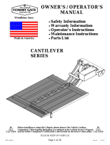
• Warnings
• Decal & Plate Locations
• Standard Control Locations
• Liftgate & Retention Ramp Operation
Operation Manual Contains:
© MAXON Lift Corp.2020
To fi nd maintenance information for your
BMR-CS Liftgate, go to www.maxonlift.
com. Click the PRODUCTS, COLUMNLIFT
& BMR-CS buttons. Open the Maintenance
Manual in the PRODUCT DOCUMENTA-
TION window. For parts, click on the PARTS
PORTAL, COLUMNLIFT & BMR-CS buttons.


TABLE OF CONTENTS
SUMMARY OF CHANGES: M-16-14, REVISION B ................5
WARNINGS ..............................................................................6
RECOMMENDED DAILY OPERATION CHECKS ...................8
DECALS & PLATES ................................................................10
STANDARD CONTROL LOCATIONS ......................................12
POWER DOWN CONTROLS (IF EQUIPPED) ........................13
PUMP BOX CONTROLS ..........................................................14
FORKLIFT ADVISORY ............................................................15
LOADING VEHICLE ................................................................16
OPENING THE PLATFORM ....................................................16
LOWERING THE PLATFORM .................................................16
OPENING THE RETENTION RAMP - STEEL PLATFORM .....17
OPENING THE RETENTION RAMP -
ALUMINUM PLATFORM ..........................................................18
POSITIONING LOAD ...............................................................19
UNLOADING VEHICLE ...........................................................22
OPENING THE PLATFORM ....................................................22
RAISING THE PLATFORM ......................................................23
LOWERING & UNLOADING PLATFORM ................................25
STOWING PLATFORM ............................................................27
STOW RETENTION RAMP ......................................................27
STOW PLATFORM ..................................................................28
DOCK LOADING & UNLOADING ............................................30
LOWER PLATFORM BELOW DOCK LEVEL...........................30


5
SUMMARY OF CHANGES: M-16-14, REVISION B
PAGE DESCRIPTION OF CHANGE
COVER Updated REV. and date of release.
8, 9 Added Recommended Daily Operational Checks.
10
Added QR Code Decal (P/N 299350-01) to decal locations
image.
11
Updated decal sheet Decal “F”, Operating Instructions, to
include QR Code Decal.

6
WARNINGS
2. Do not exceed rated load capacity of the Liftgates which is
3500 lbs. for model BMR-CS3500, and 4400 lbs. for model
BMR-CS44.
3. Do not allow any part of your body to be placed under, within, or
around any portion of the moving Liftgate or its mechanisms, or in
a position that would trap them between the platform and the fl oor
of truck body (or between platform and the ground) when Liftgate
is operated.
4. Consider the safety and location of bystanders and
location of nearby objects when operating the Liftgate. Stand
to one side of platform while operating the Liftgate. Be certain
that the area the Liftgate will move through during operation
is clear of all obstacles.
5. Comply with all attached instruction decals and warning decals.
11. Above all, USE GOOD COMMON SENSE when operating this
Liftgate.
8. Do not move vehicle unless Liftgate is correctly stowed.
6. Keep decals clean and legible. If decals are illegible or missing,
have them replaced. Get free replacement decals from Maxon.
7. Never drive a forklift on the Liftgate platform.
10. A correctly installed Liftgate will operate smoothly and reason-
ably quiet. The only noticeable noise, during Liftgate operation, is
from the power unit while the platform is being unfolded, lowered
(power down only), raised, or folded. Listen for scraping, grating
and binding noises and have the problem corrected before con-
tinuing to operate the Liftgate.
MAXON Lift Corp. Customer Service
11921 Slauson Ave
Santa Fe Springs, CA 90670
(800) 227-4116
WARNING
!
9. Correctly stow platform when not in use. Extended platforms
could create a hazard for people and vehicles passing by.
1. Incorrect operation of this Liftgate can result in serious personal
injury. Comply with WARNINGS and Liftgate operating instructions
in this manual. Do not allow untrained persons or children to oper-
ate the Liftgate. If you need to replace an Operation Manual, ad-
ditional copies are available from:
12. Never use a cell phone while operating the Liftgate.

7
THIS PAGE INTENTIONALLY LEFT BLANK

8
RECOMMENDED DAILY OPERATION CHECKS
Make sure batteries are fully charged, battery terminal connections are
clean and tight, and battery box is undamaged.
Visually check that pump cover is bolted on securely and undamaged.
Look for hydraulic fl uid leaking from the pump box.
Before operating the Liftgate, the operator should do the following:
Visually check that standard and optional controls are in place and
undamaged.
Use the operation instructions in this manual to unfold the platform
and lower it to the ground.
Check for smooth operation as platform unfolds and as runners lower
the platform to the ground.
Check for fl uid leaks from hydraulic cylinders.
Make sure load-carrying surfaces on extension plate, platform, fl ipover,
and retention ramp (if equipped) are clean (no oil, debris, or corrosion).
Visually check that all decals are in place (see DECALS page). Make
sure decals are legible, clean, and undamaged.
NOTE: Before you check the Liftgate, park vehicle on fl at ground
and set the parking brake.
NOTE: If any of the following operation checks reveal a need to
service or repair Liftgate, do not operate the Liftgate until a
qualifi ed mechanic services or repairs the Liftgate.
Make sure cab cutoff switch is ON, if equipped.
Check main frame, extension plate, columns, runners and platform
openers for cracks and bends. Make sure platform chains are undam-
aged and connected securely at both ends. Also, make sure all bolts
and pins are in place and undamaged.
Check platform and fl ipover for cracks, holes, and bends on the load-
carrying surfaces and side plates. Also, make sure retention ramps and
carts stops (if equipped) are undamaged and operate smoothly.
Follow the routing of hydraulic hoses from cylinders to pump box. Make
sure all hoses are connected at both ends and there are no cracks,
chafi ng, and fl uid leaks.

9
Use the operation instructions in this manual to operate the Liftgate
through one cycle without a load on the platform. Raise the platform
to vehicle bed height. Next, lower the platform to ground level.
When raising and lowering platform, listen for unusual noises and look
for a “jerking” motion or uneven movement at LH and RH sides of the
platform. Uneven movement should not exceed 1”.
If service or repairs are not required (or if completed), stow platform
for transport.
Retention ramps (if equipped) release, unfold and fold smoothly, and
remains in ramp, retention, and stowed positions until intentionally
moved.
Carts stops (if equipped) release, open, and close smoothly and
remain so until intentionally opened or stowed.
With platform at bed height, make sure the LH and RH platform chains
feel even in tightness.

10
FIG. 10-1
NOTE: Ensure there is no residue, dirt, or corrosion where decals are attached.
If necessary, clean surface before attaching decals.
SERIAL PLATE
FAMILY OWNED
DECAL
P/N 283445-01
DECAL “C”
DECAL “A”
DECAL “F”
DECAL “F”
DECAL “B”
YELLOW
ALIGNMENT
TAPE
P/N 090175-14
WARNING DECAL
P/N 288966-01
DECAL “D”
FAMILY OWNED DECAL
FAMILY OWNED DECAL
(2 PLACES)
(2 PLACES)
P/N 283445-01
P/N 283445-01
DECAL “E”
DECAL “E”
CAUTION DECAL
(2 PLACES)
P/N 260552
STOW WARNING DECAL
P/N 282847-01
NOTE: Decals on the Liftgate are attached at the
factory.
QR CODE DECAL
P/N 299350-01
DECALS & PLATES

11
DECAL SHEET
FIG. 11-1
DECAL SHEET PART NUMBERS
TABLE 11-1
(REFER TO TABLE 11-1)
MODEL ORDER P/N DECAL “C”
BMR-CS-35 289163-01 3500 LBS. [1600 KG]
BMR-CS-44 289163-02 4400 LBS. [2000 KG]

12
STANDARD CONTROL LOCATIONS
GROUND ACCESS - COLUMN SWITCH
Toggle switches on column switch (FIG. 12-1A)
let operator raise (UP), lower (DOWN), FOLD,
and UNFOLD the platform (FIG. 12-1) while
standing on the ground.
PLATFORM ACCESS - RUNNER SWITCH
Toggle switch (FIG. 12-2A) on RH runner lets
operator raise (UP) and lower (DOWN) the
platform (FIG. 12-2) only. Switch stays within
reach when operator rides platform UP and
DOWN.
FIG. 12-1
FIG. 12-2
FIG. 12-1A
FIG. 12-2A

13
POWER DOWN CONTROLS (IF EQUIPPED)
GROUND ACCESS - COLUMN SWITCH
POWER DOWN button (if equipped) on column
switch (FIG. 13-1A) lets operator lower platform
by pressing the POWER DOWN button once
and pushing and holding the toggle switch
(DOWN) (FIG. 13-1B), while standing on
the ground. The POWER DOWN button (FIG.
13-1A) illuminates to indicate the power down
function is activated.
FIG. 13-1B
FIG. 13-1A
POWER DOWN
BUTTON
PLATFORM ACCESS - RUNNER SWITCH
POWER DOWN button (if equipped) on runner
switch (FIG. 13-2A) lets operator lower platform
by pressing the POWER DOWN button once
and pushing and holding the toggle switch
(DOWN) (FIG. 13-2B), while standing
on the platform. The POWER DOWN button
(FIG. 13-2A) illuminates to indicate the power
down function is activated.
FIG. 13-2B
FIG. 13-2A
POWER DOWN
BUTTON

14
MASTER SELECT
SWITCH (OFF)
FIG. 14-1B
MASTER SELECT SWITCH
The master select switch (FIGS. 14-1,
14-1A and 14-1B) applies or removes
battery power from the pump(s). For a single
pump box (FIG. 14-1A), turn the MASTER
SELECT SWITCH to 1 to operate Liftgate.
PUMP BOX CONTROLS
SINGLE PUMP BOX
FIG. 14-1
If the Liftgate is equipped with a dual
pump box, the MASTER SELECT
SWITCH (FIG. 14-1A) can be used to
connect battery power to either pump 1
or pump 2 to power Liftgate. To remove
battery power from pumps 1 and 2, turn
switch OFF (FIG. 14-1B).
MASTER SELECT
SWITCH
(PUMP 1 SELECTED)
FIG. 14-1A

15
Keep forklift OFF of platform.
FORKLIFT ADVISORY
FIG. 15-1
FIG. 15-2
WARNING
!

16
LOWERING THE PLATFORM
FIG. 16-3
To lower platform to the
ground, use column switch as
shown in FIG. 16-3. Release
toggle switch when platform
reaches the ground.
LOADING VEHICLE
YELLOW
TAPE
RUNNER
ARROW
FIG. 16-2
OPENING THE PLATFORM
COLUMN SWITCH
FIG. 16-1
DOWN
FIG. 16-2A
Push toggle switch to DOWN position (FIG. 16-1)
to lower platform until runner arrow and yellow
tape
are about even (FIG. 16-2A). Platform will
be released from the locking wedges on the
Liftgate column. Next, use column switches 1
and 2 to UNFOLD platform (FIG. 16-2). Hold
both toggle switches until platform reaches the
unfolded (horizontal) position and then release
the switches.
UNFOLD
DOWN
NOTE: The 2 platform fl ashing lights are fl ashing when platform is unfolding and
unfolded. The lights stop fl ashing when the platform is folded/stowed.
1
2

17
OPENING THE RETENTION RAMP - STEEL PLATFORM
To release retention ramp,
rotate locks in direction of
arrows (FIG. 17-1) and unfold
ramp to the ground (FIG. 17-2).
RAMP IN RETENTION
POSITION
FIG. 17-1
LOCK
LOCK
FIG. 17-2
RAMP POSITION

18
OPENING THE RETENTION RAMP - ALUMINUM
PLATFORM
To unfold retention ramp, fi rst push down on retention ramp (FIG. 18-1A) to
release tension on lock. Next, push down on lock mechanism (FIG. 18-1B)
and lift the retension ramp until it is in the ramp position (FIG. 18-1C).
FIG. 18-1A
FIG. 18-1A
FIG. 18-1B
FIG. 18-1B
FIG. 18-1C
FIG. 18-1C
RAMP
POSITION
STOWED
POSITION
LOCK
(PUSH TO
RELEASE)
RAMP
LOADING VEHICLE - Continued

19
A load should never extend past the edges of the platform. Do not
place unstable loads on platform and do not allow load to exceed
lifting capacity of Liftgate. If standing on platform, do not allow your
feet to extend beyond inboard edge of platform.
WARNING
!
RAMP
INBOARD
EDGE
LOADING PLATFORM AT GROUND LEVEL
FIG. 19-1
POSITIONING LOAD
2. Move loads across the ramp
(FIG. 19-1) to the platform, but
never rest or raise loads on the
ramp. Make sure gas bottles
rest against platform railing
(FIG. 19-1A) and angle support
(FIG. 19-1B).
3. Wrap chain around each gas
bottle and hook onto platform
railing as shown in FIG. 19-1A.
If standing on platform with the
load, stand in the footprint area
shown (FIG. 19-1) and comply
with the preceding WARNING.
1. Place all loads as close as
possible to the inboard edge
of the platform with heaviest
part toward the truck body as
shown in FIG. 19-1.
FIG. 19-1A
FIG. 19-1B
FIG. 19-1B
CHAIN
CHAIN
HOOKS
ANGLE
SUPPORT
GAS
BOTTLE
PLATFORM
RAILING

20
1. Fold ramp to retention
position as follows:
RAISING & UNLOADING PLATFORM
A ramp in retention position can trip you when stepping over it.
To prevent possible injury, get on the platform before putting the
ramp in retention position.
CAUTION
!
FIG. 20-1A
RETENTION
POSITION
LOCK
LOCK
STEEL
PLATFORM
Fold ramp until it locks in
retention position (FIG.
20-2).
FIG. 20-2
RAMP
POSITION
ALUMINUM
PLATFORM
RETENTION
POSITION
FIG. 20-1
Fold ramp to retention
position and rotate
locks to secure ramp
in position (FIGS. 20-1
& 20-1A).
LOADING VEHICLE - Continued
/