Page is loading ...

1
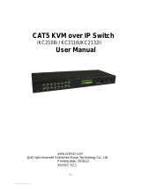
Owner’s Manual
NetDirector
®
8/16-Port 1U
Rack-Mount HDMI/USB
KVM Switch with Audio
and Peripheral Sharing
Models: B024-HU08, B024-HU16
1111 W. 35th Street, Chicago, IL 60609 USA • tripplite.com/support
Copyright © 2019 Tripp Lite. All rights reserved.
WARRANTY REGISTRATION
Register your product today and be
automatically entered to win an ISOBAR
surge protector in our monthly drawing!
tripplite.com/warranty

2
1. Product Features 3
2. Package Includes 3
3. Safety Instructions 4
4. System Requirements 5
4.1 Console 5
4.2 Computers 5
4.3 Supported Operating Systems 5
5. Introduction 6
5.1 Front Panel 6
5.2 Rear Panel 7
6. Rack-Mount Installation 8
6.1 Rack Mounting – Front 8
6.2 Rack Mounting – Rear 10
7. Installation 12
7.1 Single-Level Installation 12
7.2 Cascading 14
7.2.1 Two-Level Installation 14
7.2.2 Three-Level Installation 16
8. Multi-Display Installation 18
8.1 Cable Connections for Multi-Display Installation 18
8.2 Grouping Ports into “Vertical” Channels 20
9. Operation 21
9.1 Hot Plugging 21
9.1.1 Hot Plugging KVM Ports 21
9.1.2 Hot Plugging Console Ports 21
9.2 Port Selection 21
9.2.1 Manual Port Switching 21
9.3 Port ID Numbering 21
9.4 Powering Off and Restarting 21
10. On-Screen Display (OSD) Operation 22
10.1 OSD Overview 22
10.1.1 Manufacturing Number 22
10.1.2 OSD Login 22
10.1.3 OSD Hot Key 22
10.1.4 OSD Main Screen 22
10.1.5 OSD Main Screen Headings 23
10.1.6 Navigation 23
10.2 OSD Functions 23
10.2.1 F1: GOTO 23
10.2.2 F2: LIST 24
10.2.3 F3: SET 25
10.2.4 F4: ADM 26
10.2.5 F5: SKP 28
10.2.6 F6: BRC 28
10.2.7 F7: SCAN 28
10.2.8 F8: LOUT 29
11. Hot Key Operation 30
11.1 Hot Key Commands 30
11.2 Hot Key Setting Mode 30
11.2.1 Invoking HSM 30
11.3 Select the Active Port 30
11.4 Auto Scan Mode 31
11.4.1 Invoking Auto Scan 31
11.5 Skip Mode 31
11.6 Keyboard/Mouse Reset 32
11.7 Hot Key Beeper Control 32
11.8 Quick Hot Key Control 32
11.9 OSD Hot Key Control 32
11.10 Port OS Control 32
11.11 Restore Default Values 33
11.11.1 USB Reset 33
11.11.2 Hot Key Beeper Control 33
11.11.3 Mouse Emulation Control 33
11.12 HSM Summary Table 34
12. Keyboard Emulation 35
12.1 Mac Keyboard 35
12.2 Sun Keyboard 36
13. Firmware Management Utility 37
13.1 Introduction 37
13.1.1 Downloading the Firmware Upgrade Package 37
13.2 Preparation 37
13.3 Starting the Upgrade 38
13.4 Upgrade Succeeded 39
13.5 Upgrade Failed 39
13.6 Firmware Upgrade Recovery 40
13.7 OSD Configuration Backup/Restore 40
13.7.1 Backup 40
13.7.2 Restore 41
14. Appendix 42
14.1 Factory Default Hot Keys and Settings 42
14.2 Specificiations 42
15. Warranty & Product Registration 43
Table of Contents

3
1. Product Features
2. Package Includes
• Control up to eight (B024-HU08) or 16 (B024-HU16) HDMI computers and two USB 2.0 peripheral devices using one centralized monitor,
keyboard and mouse.
• Cascade up to three levels with the B024-HU08 (control up to 512 computers) or two levels with the B024-HU16 (control up to 256
computers).
• Effortlessly switch between computers using either the front panel buttons, hot keys or on-screen display (OSD).
• The KVM and USB focus can be switched independently of one another; for example, you can access one computer while simultaneously
printing from another computer.
• Support HDMI video resolutions up to 1920 x 1200 @ 60 Hz.
• Console mouse emulation supports multi-functional mice and most mouse drivers.
• OSD Backup/Restore feature allows the administrator to back up the switch’s configurations and user profile information.
• B024-HU08 or B024-HU16
• HDMI/USB Custom KVM Cable Kits (x2) – 6 ft.*
• Firmware Upgrade Cable – 6 ft.
• External Power Supply with C13 to NEMA 5-15P Power Cord (Input: 100-240V, 50/60 Hz, 0.7A; Output: 5V 4A)
• Rubber Feet (x4)
• Mounting Hardware
• Quick Start Guide
* Note: The microphone connector on the cable kit will not be used because the B024-HUXX supports speakers only.
Optional Accessories
• P569-Series High Speed HDMI Cables
• UR022-Series USB 2.0 Reversible A/B Cables
• P312-Series 3.5mm Mini Stereo Audio Cables
• P782-0XX-HA HDMI/USB/Audio Custom KVM Cable Kits*
* P130-000 HDMI to DVI adapter sold separately.

4
• Read all instructions and save for future reference.
• Follow all warnings and instructions marked on the device.
• Do not place the device on any unstable surface (cart, stand, table, etc.); if the device falls, serious damage will result.
• Do not use the device near water.
• Do not place the device near or over radiators or heat registers. The device cabinet’s slots and openings allow for adequate ventilation. To
ensure reliable operation and to protect against overheating, these openings must never be blocked or covered.
• The device should never be placed on a soft surface (bed, sofa, rug, etc.), as this will block its ventilation openings. The device should also not
be placed in a built-in enclosure, unless adequate ventilation is provided.
• Never spill liquid of any kind onto the device.
• Unplug the device from the wall outlet before cleaning. Do not use liquid or aerosol cleaners. Always use a damp cloth for cleaning.
• The device should operate from the power source type as indicated on the marking label. If unsure what power type is available, consult your
dealer or local power company.
• Do not allow anything to rest on the power cord or cables. Route power cord and cables so they cannot be stepped on or tripped over.
• If an extension cord is used with this device, make sure the total ampere ratings of all products used on this cord does not exceed the
extension cord ampere rating. Make sure the total of all products plugged into the wall outlet does not exceed 15 amperes.
• To help protect your system from sudden transient increases and decreases in electrical power, plugging your devices into a Tripp Lite surge
protector, line conditioner, or uninterruptible power supply (UPS) is recommended.
• When connecting or disconnecting power to hot-pluggable power supplies, observe the following guidelines:
• Install the power supply before connecting the power cable to the power supply.
• Unplug the power cable before removing the power supply.
• If the system has multiple sources of power, disconnect power from the system by unplugging all power cables from the power supplies.
• Never push objects of any kind into or through cabinet slots. They may touch dangerous voltage points or short out parts resulting in a risk of
fire or electrical shock.
• Do not attempt to service the device. Refer all servicing to qualified service personnel.
• If the following conditions occur, unplug the device from the wall outlet and bring it to qualified service personnel for repair.
• The power cord or plug has become damaged or frayed.
• Liquid has been spilled into the device.
• The device has been exposed to rain or water.
• The device has been dropped, or the cabinet has been damaged.
• The device exhibits a distinct change in performance, indicating a need for service.
• The device does not operate normally when the operating instructions are followed.
• Only adjust controls covered in the operating instructions. Improper adjustment of other controls may result in damage that will require
extensive work by a qualified technician to repair.
• Do not connect the RJ11 port on the KVM marked UPGRADE to a public telecommunications network.
• The device is designed for IT power distribution systems with 120V phase-to-phase voltage.
• To prevent damage to your installation, it is important that all devices are properly grounded.
3. Safety Instructions

5
4.1 Console
• HDMI-compliant monitor
• USB Mouse/Keyboard
• Speakers (Optional)
4.2 Computers
• Source with an HDMI port
• USB Type-A port
• Speaker ports (Optional)
4.3 Supported Operating Systems:
Operating System Version
Windows 2000 and higher
Mac OS 9.0 and higher
Linux Kernal 2.6 and higher
RedHat 9.0 and higher
SuSE 10 / 11.1 and higher
Debian 3.1 / 4.0
Ubuntu 7.04 / 7.10
UNIX AIX 4.3 and higher
FreeBSD 5.5 and higher
Sun Solaris 8 and higher
Novell Netware 6.0 and higher
4. System Requirements

6
5. Introduction
5.1 Front Panel
Key Component Description
A Port Selection Pushbuttons
For manual port selection (for details, see section 9.2 Port Selection):
• Press a port selection pushbutton for less than two seconds to bring the KVM, USB hub, and audio focus to the
computer attached to its corresponding port.
• Press a pushbutton for longer than two seconds to bring the KVM and audio selection to the computer attached
to its corresponding port.
• Press pushbuttons 1 and 2 simultaneously for 2 seconds to start Auto Scan Mode (for details, see section 11.4
Auto Scan Mode).
• Press pushbuttons 7 and 8 simultaneously for 2 seconds to perform a keyboard and mouse reset (for details, see
section 11.6 Keyboard/Mouse Reset).
• For independent switching, enable mouse emulation (see section 11.11.3 Mouse Emulation Control).
B Port LEDs The Port LEDs are built into the Port Selection Switches. The KVM Port LEDs are on the left. The USB LEDs are on
the right.
KVM
• Illuminates dim orange to indicate the computer attached to the corresponding port is up and running (On Line).
• Flashes to indicate Firmware Upgrade mode is in effect.
• Illuminates bright orange to indicate the computer connected to the corresponding port has the KVM focus
(Selected).
• Flashes to indicate the computer connected to the corresponding port is being accessed under Auto Scan mode.
USB
• Lights green to indicate the computer connected to the corresponding port is the one with access to the
USB peripherals.
C Firmware Upgrade Recovery Switch During normal operation and while performing a firmware upgrade, the switch should be in the NORMAL position.
If a firmware upgrade operation does not complete successfully, this switch is used to perform a firmware upgrade
recovery (for details, see section 13.6 Firmware Upgrade Recovery).
D Audio Port Connect speakers to this port (optional). The speakers plugged into this connector have priority over those plugged
into the rear panel.
E Firmware Upgrade Port This port is used to upgrade the firmware on the KVM switch. Connect the included Firmware Upgrade Cable to this port.
F USB 2.0 Hub USB 2.0 peripherals (printers, scanners, etc.) can be connected to the port (a user-supplied power adapter may be
required).
Note: The USB 2.0 hub cannot be accessed through the switch by computers on the second or third level or a
cascaded installation.
G Reset Switch Pressing this switch performs a system reset. When the system is reset, the unit beeps and the port LEDs flash in
succession until the reset is complete. After the reset is complete, you can log in again.
H Power LED Illuminates to indicate the switch is powered and ready to operate.
A
A
B
B
C
C
D
D
E
E F
G
G
H
H
Model B024-HU08
Model B024-HU16
F

7
Key Component Description
I Power Jack The power adapter cable connects here.
J Console Port Selection The cables from the console HDMI monitor, USB keyboard, USB mouse and speakers connect here.
Each connector is marked with an appropriate icon to indicate the connector type.
K Grounding Terminal Connect a grounding wire to ground the switch (optional).
L USB 2.0 Hub USB 2.0 peripherals (printers, scanners, etc.) can be connected to the port.
Note: The USB 2.0 hub cannot be accessed through the switch by computers on the second or third level of a
cascaded installation.
M KVM Port Selection Cables that link the switch to the computers connect here. Each KVM port selection includes a speaker jack,
a USB Type-B connector and an HDMI connector with screw lock.
5.2 Rear Panel (Model B024-HU08 shown)
5. Introduction
I J
K L
M

8
6. Rack-Mount Installation
6.1 Rack Mounting – Front
1. Remove screws, one each from the left and right sides near the front of the switch.
2. Use the M3 x 8 Phillips hex head screws supplied with the rack mounting kit to screw the rack mounting brackets into the sides near the front
of the unit.

9
6. Rack-Mount Installation
3. Place the KVM switch in the rack. Position it so that the holes in the mounting brackets line up with the holes in the rack. Secure the
mounting brackets to the front of the rack.

10
6. Rack-Mount Installation
6.2 Rack Mounting - Rear
1. Remove the screws, one each from the left and right sides near the rear of the switch.
2. Use the M3 x 8 Phillips hex head screws supplied with the rack-mounting kit to screw the brackets into the sides near the rear of the unit.

11
6. Rack-Mount Installation
3. Place the KVM switch in the rack. Position it so the holes in the mounting brackets line up with the holes in the rack. Secure the mounting
brackets to the rear of the rack.
Note – Before beginning installation:
• Make sure power to all devices that you will be connecting has been turned off
• Properly ground the KVM switch to prevent damage to your installation from surges or static electricity

12
7. Installation
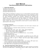
7.1 Single-Level Installation
To set up single-level installation, refer to the installation diagram on the following page (the numbers in the diagram correspond to the steps
below) and perform the following:
1. Plug a USB keyboard and a USB mouse in the USB console ports located on the unit’s rear panel.
2. Connect an HDMI monitor into the HDMI console port and power it on.
3. Plug primary speakers into the speaker jack located on the unit’s front panel. Speakers plugged into the rear panel will be secondary to these
speakers.
4. Plug secondary speakers into the audio port located on the unit’s rear panel (optional).
5. Using Tripp Lite’s P782-0XX-HA HDMI/USB/Audio KVM cable kit or individual HDMI, USB and audio cables, plug the HDMI connector into any
available HDMI port, then plug in the accompanying USB and audio cables to their corresponding ports.
6. At the other end of the cable, plug the USB, video and speaker cables into their respective ports on the computer.
7. Plug USB peripherals into the Type-A connectors in the USB hub section.
8. Plug the power adapter that came with the switch into an AC power source, then plug the power adapter cable into the switch’s power jack.
9. Power on connected computers.

13
7. Installation
8
4
1
3
7
7
2
USB HDMI
KVM Cable Set
5
HDMI
6
USB HDMI
KVM Cable Set

14
7. Installation
7.2 Cascading
7.2.1 Two-Level Installation
To control even more computers, additional B024-HU08 or B024-HU16 units can be cascaded from the KVM ports of the first-level unit. The
cascaded B024-HUXX KVMs that connect back to the first-level unit are considered second-level units. As many as 64 (B024-HU08) or 256
(B024-HU16) computers can be controlled in a complete two-level installation.
To set up two-level installation, refer to the following Two-Level Installation diagram (the numbers in the diagram correspond to the steps below)
and perform the following:
1. Make sure power to all the devices you will be connecting, including all previously installed devices, has been turned off.
2. Using Tripp Lite’s P782-0XX-HA HDMI/USB/Audio KVM cable kit or individual HDMI, USB and audio cables, connect any available KVM port on
the first-level unit to the console port of the second-level unit.
Note: Plug the USB Type-A connector into the lower USB (keyboard) port in the Console section. Connectors are marked with icons to indicate
the correct USB port.
3. Using another Tripp Lite P782-0XX-HA HDMI/USB/Audio KVM cable kit or individual HDMI, USB and audio cables, plug the HDMI connector
into any available HDMI port on the second-level unit, then connect the accompanying USB and audio cables to their corresponding ports.
4. At the other end of the cable, plug the USB Type-A, video and speaker cables into their respective ports on the computer.
5. Repeat steps 3 and 4 for any other computers you are connecting.
6. For each second-level unit, plug the power adapter cable into its power jack, then plug the power adapter into an AC source.
7. Plug the first-level unit’s power adapter cable into its power jack, then plug the power adapter into an AC source.
8. Power on connected computers.
Notes:
• The power-on sequence requires that all second-level units be powered on first. After all are on, the first-level units must be powered on next.
Only after all switches have been powered on in this sequece, can the computers be powered on.
• The USB 2.0 hub cannot be accessed through the switch by computers on the second or third level of a cascaded installation.

15
7. Installation
Two-Level Installation Diagram
USB HDMI
KVM Cable Set

16
7. Installation
7.2.2 Three-Level Installation – B024-HU08 Only
The procedures for setting up a three-level installation are the same as for a two-level installation. Using the B024-HU08 in a three-level setup,
as many as 512 computers can be controlled.
Notes:
• The B024-HU08 cannot be cascaded beyond the third level and the B024-HU16 cannot be cascaded beyond the second level.
• The B024-HU08 can only be cascaded with other B024-HU08 units.
Once all cables have been connected (refer to section 7.2.1 Two-Level Installation) to the third-level KVMs, power up devices according to
the following sequence:
1. For each third-level unit, plug the power adapter cable into the switch’s power jack. Plug the power adapter into an AC source.
2. For each second-level unit, plug the power adapter cable into the switch’s power jack. Plug the power adapter into an AC source.
3. Plug the first-level unit’s power adapter into its power jack. Plug the power adapter into an AC source.
4. Power on all computers.

17
7. Installation
Three-Level Installation Diagram
USB HDMI
KVM Cable Set
USB HDMI
KVM Cable Set

18
8. Multi-Display Installation
The B024-HU08 / B024-HU16 include a multi-display feature to support two, three, four or up to eight units in a dual/triple/quad-display/multi-
display installation to control up to seven (B024-HU08) or fifteen (B024-HU16) computers at once. This installation requires slightly different
cabling than the standard cascade and offers an extra level of switching flexibility for multiple-monitor installations where each computer is fitted
with multiple video cards.
Note: In a Multi-display installation, the B024-HU08 can only be connected to B024-HU08 units, and the B024-HU16 can only be connected
to B024-HU16 units.
8.1 Cable Connections for Multi-Display Installation
To set up a multi-display installation, refer to the following installation diagram (the numbers in the diagram correspond to the steps below) and
perform the following steps:
1. Use a standard USB Type-A to USB Type-B cable to connect the Port 8 USB port on the first-stage unit to the USB port in the Console section
of the second switch.
Note: Port 8 is reserved to connect the units in a multi-display installation, so up to seven (B024-HU08) or fifteen (B024-HU16) computers
can be attached, using KVM ports 1–7 (B024-HU08) or ports 1–7/9–16 (B024-HU16).
2. Use HDMI cables to connect the HDMI KVM port on the second B024-HU08 / B024-HU16 unit to the second video-in port on the computer.
Note: Only HDMI video cables are necessary – the other ports in the KVM section are not required in this installation.
3. Connect a display to the console section of the second switch.
4. Repeat steps 1-3 for any additional units, up to eight switches.
5. Connect the cables for the first switch. See section 7.1 Single-Level Installation for full details. All video, audio and peripheral devices must
be connected to the first switch.
6. Power up the B024-HU08 / B024-HU16 units starting with the first switch, then power on the computers.

19
8. Multi-Display Installation
Multi-Display Installation Diagram
5
Computers with
2/3/4 video inputs
First Switch
5
HDMI cables
5
1
USB Type B to
Type A cable
Second Switch
3
Third / Fourth
Stage Units
4
2

20
8. Multi-Display Installation
8.2 Grouping Ports into “Vertical” Channels
Once the cables have been connected and multi-display mode has been selected in the on-screen display, the B024-HU08 / B024-HU16 auto-
detects the channels and displaying modes. Users can then assign channel numbers as port names (the channels are represented by the vertical
columns in the diagram below). So, each Port 1 becomes Channel 1, each Port 2 becomes Channel 2, etc. The ports will all be switched at the
same time, channel by channel.
Depending on the number of stages in your stack, a B024-HU08 / B024-HU16 installation offers dual display (two stages), triple display (three
stages), quad display (four stages) or multi-display scenarios, up to eight stages. For reference, the example shows a four-stage installation with
quad display functionality.
Note: Only one HDMI video signal can be displayed at a time, depending on the configuration of the B024-HU08 / B024-HU16 unit on the first switch.
Channels Diagram
Ch1
Ch7 Ch6
First
Switch
Second
Switch
Third
Switch
Fourth
Switch
/