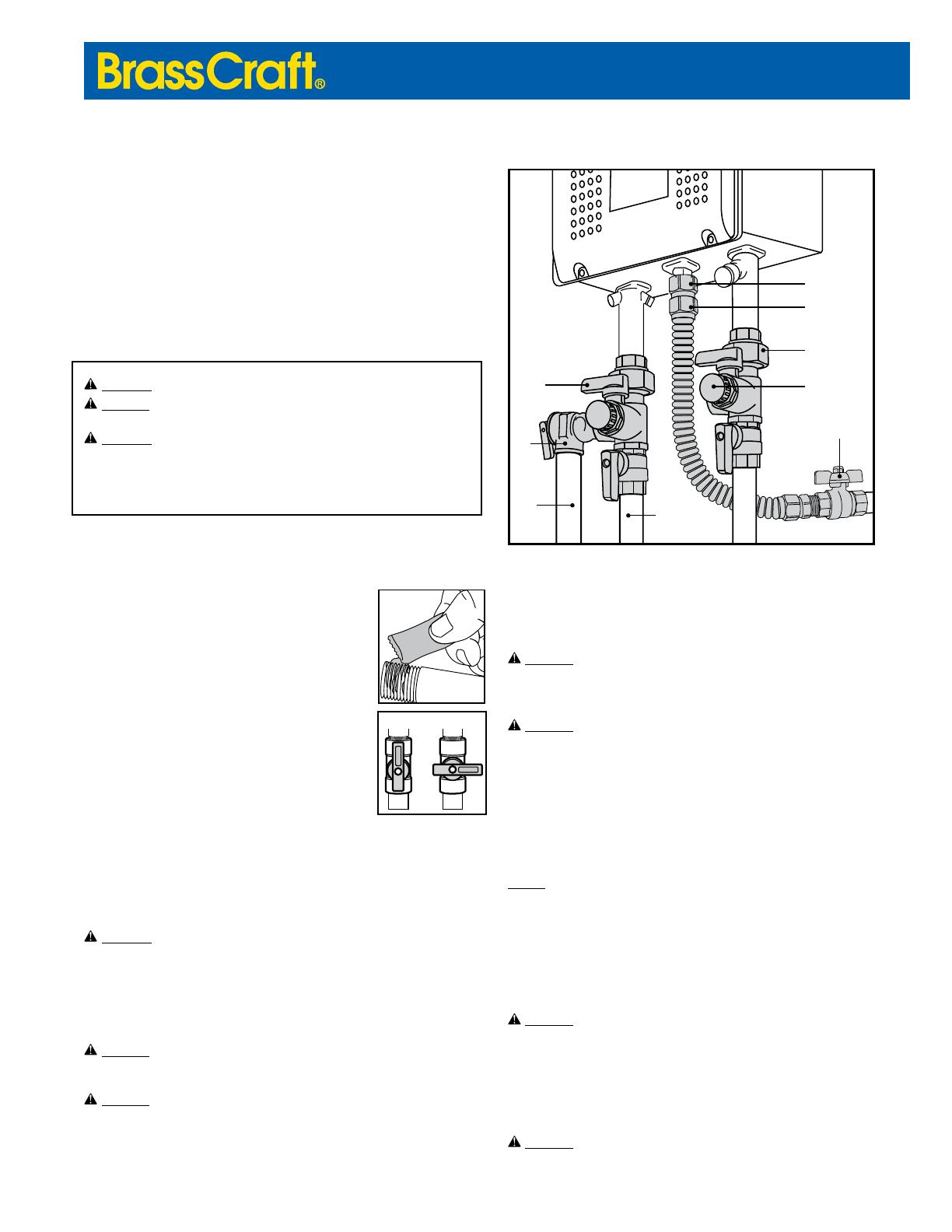
Tankless Water Heater Installation Kit
Drain Port
Handle
PR
Valve
Discharge
Line
Hot Water
Distribution
Pipe
Gas Connector
Nut
Adapter
Coupling Nut
Drain Port Cap
Full Port
Gas Ball Valve
INSTALLATION INSTRUCTIONS
As the world leader in gas and water products, BrassCraft’s
tankless water heater installation kits simplify the appliance
installation with fewer connections and a clean, professional
nish. Featuring independent, 1/4 turn water control, BrassCraft
service valves make it simple to service & test the appliance.
When it comes to mastering a professional installation with high
quality components, BrassCraft is the hottest name in tankless
water heater installations.
WARNING: Read all instructions & precautions before beginning installation
WARNING: Follow all installation instructions of the tankless water heater
manufacturer when
installings ervicing the water heater and its connections.
WARNING: Expansion tank is required if a backow preventer is installed
upstream of the tankless water heater.
Check with your local and state inspection ofce for applicable code requirements.
Installation may require a permit & inspection.
Installing the Hot/Cold Service Valves and
Pressure Relief Valve (PR Valve):
1. Turn off water supply at shut-off valve near appliance
location. In absence of valve near appliance, water MUST
be shut off at main valve, near the meter.
2. Remove the coupling nut from the hot service valve body
(red handles).
3. Clean all male and female pipe threads with a wire brush
and rag to ensure connections are free of any debris such
as metal shavings, rust, dirt, oil or water.
4. Apply pipe thread tape or sealant (as shown) to all male
pipe threads of connection.
5. Thread the coupling nut onto the outlet of the tankless
water heater, wrench tighten.
6. Thread the outlet of the hot service valve body onto the
hot water distribution pipe, wrench tighten.
7. Thread the body of the hot water service valve into the
coupling nut, wrench tighten.
8. Verify that the drain port cap is tight, and that the drain port handle is in the closed
position (pointing 90 degrees from the outlet as shown).
9. Then thread the PR valve into the open port provided on the side of the hot service
valve. Be sure that the outlet of the PR valve points down.
WARNING: Do not install a manually operated shut-off valve before or after the
PR valve; doing so may cause the system to over-pressurize & fail which may
result in property damage, personal injury and/or death.
10. Thread a 3/4" discharge line (drain line) to the outlet of PR valve. The line must
discharge within 6" of an approved location or drain. A discharge line may NOT
be directly connected to a sewer line. In addition, a reducing coupling or other
restriction is NOT permitted. End of line must be plain, not threaded.
WARNING:
Discharge line must be allowed to drain dry to ensure that no water
can pool and freeze; frozen water near valve outlet will interfere with valve
operation which may result in property damage, personal injury and/or death.
WARNING:
Discharge line must be directed so hot water cannot splash on
equipment or persons in vicinity if valve discharges which may result in property
damage, personal injury and/or death.
11. Repeat installation for the cold service valve (blue handles) in the same manner
as above (with exception that no PR valve is required).
Installing the Gas Connector (and Gas Ball Valve):
WARNING:
Gases can be ignited by a ame or spark causing a re or explosion
which may result in property damage, personal injury and/or death. Remove all
sources of ignition (matches, candles, open ames, etc) before beginning
installation. Follow installation instructions carefully.
OPEN
CLOSED
WARNING:
To reduce the risk of gas leaks:
•DONOTreuseconnectors,ttingsandvalves;theyaredesignedforuseon
original installation only. Removal of connector and additional handling may
damage connector making it unsafe for reuse.
•DONOTusethisconnectorifithasbeeninare.Firecandamagethe
connector making it unsafe for use.
•DONOTjointhisconnectortoanotherconnector.
•DONOTconnectgasconnectornutsdirectlytopipethreadsofgassupplypipe
or appliance. Install connector using the ttings provided.
NOTICE:
Fuel gas codes require installation of a gas ball valve in the same room, within
easy reach of the appliance (i.e. within 6 feet).
1. Turn off gas supply at gas ball valve near appliance location. In absence of a
valve near appliance, gas MUST be shut off at main valve, near the meter.
2. Clean all male and female pipe threads with a wire brush and rag to ensure
connections are free of any debris such as metal shavings, rust, dirt, oil or water.
3. Apply pipe thread sealant or yellow gas thread tape to the male pipe threads
of connection.
WARNING:
DO NOT apply sealant or tape to ared ends of adapter ttings. Sealant
and tape will prevent this connection from sealing properly which may result in
a gas leak.
4. If necessary, thread new gas ball valve onto gas supply pipe, wrench tighten.
5. Thread adapter tting into gas ball valve and other adapter tting onto appliance
gas inlet.
6. Thread gas connector nuts onto adapter ttings. Wrench tighten all connections.
WARNING:
To reduce the risk of gas leaks:


