Page is loading ...

Ocean Electric Winches
Models 40 – 111
Issue 4
TO BE KEPT WITH BOAT DOCUMENTS
BEI DEN SCHIFFSPAPIEREN AUFBEWAHREN
A CONSERVER AVEC LES DOCUMENTS DU BATEAU
PA ADJUNTAR A LA DOCUMENTACIÓN DE LA EMBARCACION
BÖR FÖRVARAS I BÅTEN

Page 2
CONTENTS
CONTENTS Page
Introduction
Warnings 3
Installation
Identifying the manual convertible winch 4-5
Preparing the manual winch for conversion 4-5
Positioning/installation of complete electric winch 6-10
Electrical Installation
Electrical wiring installation 11
Electrical connections 12
Wiring diagram single speed 40 to 48 - 12V & 24V 13
Wiring disgram single speed 50 to 64 - 12V & 24V 14
Wiring diagram 2 & 3 speed 64 to 111 - 12V & 24V 15
Performance Diagrams
Models 40 to 44 16
Models 48 to 66/3 17
Models 77/3 to 88/3 18
Rope Diameters 18
Maximum Loads 18
Operating Your Winch 19
Servicing Your Winch 20
Parts List 21
Models 40 to 48 22
Models 50 to 64 22
Models 66 to 111 23
Dimensions 24
Total Weight 24
Fault Finding 25
Electric Convertible Model Range 26
Lewmar Limited Warranty 27

Page 3
IMPORTANT
Read this before installing and Operating your Electric Winch
Dear Customer,
Thank you for having chosen Lewmar Electric Ocean Winches. Lewmar
products are world renowned for their quality, technical innovation and
proven performance. With a Lewmar winch you will be provided with
many years of outstanding service. We wish you happy sailing.
Warning!
Please ensure that you thoroughly understand the operation and safety
requirements of the winch before commencing the installation. Only
persons who are completely familiar with the controls and those who
have been fully made aware of the correct use of the winch should be
allowed to use it. If there is any doubt of how to install or operate this unit
please seek advice from a suitably qualified engineer.
Warning!
Winches used incorrectly could cause harm to equipment or crew.
Winches should be used with care and treated with respect.
Sehr geehrter Kunde,
vielen Dank für die Auswahl einer Lewmar-Winsch für Ihr Schiff. Lewmar-
Produkte sind weltweit bekannt für Qualität, innovative Technik und
Langlebigkeit. Mit einer Lewmar-Winsch werden Sie viele Jahre Freude
am Segeln haben. Wir wünschen Ihnen viel Spaß dabei.
ACHTUNG!
Achten Sie darauf, daß Sie die Anwendungs- und Sicherheitshinweise
dieser Anleitung vor Beginn der Montage vollständig verstanden haben.
Achten Sie darauf, daß nur Personen die Winsch bedienen, die den
Umgang hiermit beherrschen. Sollten Sie hierzu Fragen haben, dann
sprechen Sie Ihren Lewmar-Partner an.
ACHTUNG!
Unsachgemäß bediente Winschen können Schäden an Crew und
Mannschaft verursachen. Winschen sollten bedacht eingesetzt und mit
Respekt gewartet werden.
Cher Client,
Merci pour la confiance que vous nous accordez en ayant choisi les
winchs électriques LEWMAR OCEAN. Les produits LEWMAR sont réputés
dans le monde entier pour leurs qualités, leurs innovations techniques et
leurs performances. Votre winch LEWMAR va vous procurer de nombreux
services pendant longtemps. Nous vous souhaitons une agréable
navigation.
ATTENTION !
Assurez-vous, avant toute opération de montage, que vous avez
parfaitement compris comment fonctionne ce winch ainsi que les
impératifs de sécurité. Seules les personnes habituées à son maniement
ou celles qui ont été parfaitement informées du mode de fonctionnement
doivent être autorisées à l’utiliser. En cas de doute sur son installation ou
sur son utilisation, consultez un technicien compétent.
ATTENTION !
Un winch mal utilisé peut causer des accidents ou des dommages tant
aux personnes qu’au matériel. Les winchs doivent être utilisés avec
attention et respect.
INTRODUCTION
Apreciado cliente:
Gracias por elegir winches eléctricos Lewmar Ocean. Los productos
Lewmar tienen renombre mundial por su calidad, innovaciones técnicas
y probadas prestaciones. Con un winche Lewmar obtendrá muchos
años de servicio sin igual. Le deseamos felices singladuras.
Atención!
Asegúrese de entender el funcionamiento y los requisitos de seguridad
del winche antes de empezar la instalación. Solo se debe permitir usar el
winche a aquellas personas que estén totalmente familiarizadas con los
mandos y que hayan sido instruídas sobre la correcta utilización del
winche. Si existe alguna duda sobre como instalar o hacer funcionar
este producto, debe buscarse ayuda de un mecánico cualificado.
Atención!
Los winches utilizados incorrectamente pueden causar daños a los
tripulantes o material. Los winches deben usarse con cuidado y tratados
con respeto.
Bäste kund
Tack för ditt val av Lewmar´s Ocean elvinschar. Våra produkter är kända
över hela världen för hög kvalitet, tekniskt nytänkande och
väldokumenterade prestanda. Med en vinsch från Lewmar kan du räkna
med många års överlägsen funktion. Trevlig segling.
Varning!
Var noga med att tillägna dig alla anvisningar avseende handhavandet
och säkerheten innan du påbörjar installationen. Var och en som
använder vinscharna bör vara helt insatta i hur kontrollerna fungerar och
hur vinscharna skall användas. Tveka inte att kontakta en kvalificerad
tekniker om du känner dig osäker på hur vinscharna skall installeras
eller användas.
Varning!
En vinsch som används felaktigt kan skada såväl utrustning ombord
som andra besättningsmedlemmar. Använd dem därför med försiktighet
och respekt.

Page 4
INSTALLATION
Preparing the Manual Winch for Conversion to Electric (Fig. 2)
Remove the winch from the deck (if already installed) and remove the
Centre Plate, which is located on the underside of the Centre Stem, by
using a soft hammer and punch.
Remove any sharp edges and clean, to remove all old bedding/sealing
compounds from the underside of the Centre Stem.
Fitting a Complete Electric Winch from New
Test fit the winch to the Power Drive Base and Gearbox to check the
orientation and the necessary clearence needed BEFORE DRILLING ANY
HOLES.
Now follow the positioning/installation section from page 6.
1992
1992
AUG 2000 AUGUST 2000
Wavegrip Winch
Ocean
Wavespring Manual
Convertible
Manual
Convertible Manual
with Power Drive Unit
Complete Electric
Convertible Winch
A
B
C
ALLE WINSCHEN VOR DER OCEAN-SERIE (VOR BAUJAHR
1992) KÖNNEN NICHT AUFGERÜSTET WERDEN. MERKMAL
FÜR BAUJAHR VOR/BIS 1992: FESTER SELF TAILER!
Identifizierung der aufrüstbaren Winsch (Fig. 1)
Lewmar markiert das Centre Stem jeder Winsch mit einem Datum. A/00
oder 00/A = Januar 2000. B/00 oder 00/B = Februar 2000. C/00 oder 00/
C = März 2000, usw. .
Aufrüstbare, manuelle Winschen im August 2000 hergestellt sind markiert
mit H/00 oder 00/H auf dem Centre Stem (H = August, 00 = Jahr 2000).
Ebenfalls ist ein blauer Aufkleber auf der Topkappe, der die Benutzung
der Winschkurbel und manuelle Nutzung einer elektrischen Schotwinsch
darstellt. Diese Winschen können mit der Power-Basis (B), der elektrischen
Antriebseinheit (C), der Control Box und dem Deckstaster (für wahlweise
12V oder 24V) aufgerüstet werden.
Manuelle “Ocean Wave Spring” Winschen, die zwischen 1992 und Juli
2000 (G/00) hergestellt wurden, besitzen NICHT den nötigen Centre Stem
zur Aufrüstung zur elektrischen Winsch!
Ein Centre Stem Kit (A) zur Umrüstung von frühen Ocean Winschen, von
1992 bis Juli 2000 (nur Centre Stem!) ist lieferbar. Die Teilenummern sind
unten aufgeführt.
PRE OCEAN WINCHES, I.E. FIXED JAW WAVE GRIP WINCHES,
MADE BEFORE 1992 ARE NOT CONVERTABLE.
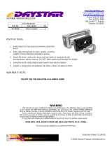
Identifying the Manual Convertible Winch (Fig. 1)
Convertible manual winches made in August 2000 will be date marked
H/00 on the centre stem, (H = August; 00 = year 2000). They also carry
a blue sticker on the screw-on top-cap showing a winch handle and a
hand operating an electric deck switch. These winches can be converted
by adding the Power Drive Base (B) unit and the required Motor Gearbox
(C), Control Box and Switch-gear (12V or 24V).
Ocean Wave Spring manual winches made between 1992 and August
2000 are NOT fitted with the necessary centre stem to convert to powered
operation. A Centre Stem Kit (A) is available to convert the early Ocean
Wave Spring winches from (1992 to July 2000). The part numbers are
listed on page xx. Pre Ocean Winches, i.e. fixed jaw Wave Grip winches,
made before 1992 are NOT convertable.
Winch Model Description Part Number
40ST Centre Stem Kit 48040038
44ST Centre Stem Kit 48044038
48ST Centre Stem Kit 48048038
Vorbereitung der manuellen Winsch zur Aufrüstung zu
elektrischem Antrieb (Fig. 2)
Demontieren Sie die Winsch von Deck (wenn noch montiert) und
entnehmen Sie die Centre Platte, welche auf der Unterseite des Centre
Stems eingelegt ist. Verwenden Sie wenn nötig einen Gummihammer
zum Austreiben der Platte nach innen.
Entfernen Sie alle Grate und säubern Sie das Centre Stem gründlich von
eventuellen Verschmutzungen. Auch eventuelle Rückstände von
Dichtmaterialien. Die Grundfläche muß absolut sauber sein.
Montage einer kompletten, neuen Elektro-Winsch.
Fügen Sie die Winsch vor der Montage mit der Antriebseinheit zum Test
zusammen. Prüfen Sie die Position des Motors unter Deck und die
notwendigen Räume zur Montage bevor Sie Löcher ins Deck bohren!
Nun folgen Sie den Punkten Anordnung und Montage in dieser
Montageanleitung auf Seite 6.
Winch Model Description Part Number
40ST Centre Stem Kit 48040038
44ST Centre Stem Kit 48044038
48ST Centre Stem Kit 48048038
FIG. 1

Page 6
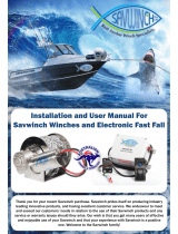
1. Lewmar recommend that the rope enters onto the drum at an angle
of -5
o
to -10
o
to the base axis of the winch. To achieve this angle it
may be necessary to use a base wedge when installing the winch.
The winch must be mounted on an even surface.
Always keep in mind the space available below the deck for the
motor gearbox.
2. If practical, for best performance, the winch should be installed so
that the output gear is situated in the optimum position in relation to
the load.
Use the template provided as a guide to drill/cut holes in deck.
1. Lewmar empfiehlt einen Eintrittswinkel des Tauwerks auf die
Winschtrommel von 5 bis 10°. Um dies einzuhalten ist unter
Umständen die Montage eines Ausgleichskeiles nötig. Die Winsch
muß auf eine absolut ebene Fläche montiert werden.
Beachten Sie stets den nötigen Raum unter Deck für die Motor/
Getriebeeinheit.
2. Wenn möglich sollte die Winsch so montiert werden, daß das
antreibende Zahnrad der Trommel an der optimalen Stellung in
Relation zur Last steht. Diese Position ist dort, wo die höchste Last
auf die Trommel eintritt.
Verwenden Sie die Deckschablone zur Positionsfindung.
1. Il est recommandé de respecter un angle d’attaque du cordage
sur le tambour du winch, de 5° minimum à 10° maximum par rapport
à l’axe vertical du winch. Il peut être nécessaire pour obtenir cet
angle d’installer une platine inclinée sous la base du winch. Le winch
doit être monté sur une surface parfaitement plane.
Il faut toujours prévoir un espace suffisant sous le pont pour loger
le moteur.
2. Si possible, et pour un meilleur rendement, le winch devrait être
monté de telle façon que le pignon d’entraînement soit situé dans
sa position de rendement optimum, c’est-à-dire au point d’attaque
du cordage.
Utiliser le gabarit de perçage fourni avec le winch.
1. Lewmar recomienda que el cabo entre en el tambor con un ángulo
de 5 a 10º con el eje de la base del winche. Para conseguir dicho
ángulo puede ser necesario usar una cuña bajo la base al instalar
el winche.
El winche debe ser instalado en una superficie plana y regular.
Debe tenerse siempre en cuenta el espacio disponible bajo cubierta
para el motor y reductora.
2. Para consequir las mejores prestaciones prácticas, el winche se
debe instalar de manera que el engranaje de ataque este situado
en la posición óptima en relación a la dirección de la carga.
Usar la plantilla que se adjunta como guía para taladrar y cortar la
cubierta.
1. Lewmar rekommenderar att skotets inkommande part bildar en
vinkel på 5
o
till 10
o
med vinschens huvudaxel. För att uppnå denna
vinkel kan det vara nödvändigt att montera vinschen på en kilplatta.
Vinschen måste monteras på ett plant underlag.
Kontrollera att det finns utrymme under däck för vinschens motor/
växellåda.
2. För bästa möjliga funktion bör vinschen, om möjligt, placeras med
det utgående drevet i optimalt läge i förhållande till lasten.
Använd den medlevererade mallen och markera monteringshålens
läge på däcket.
-5 to -10
o
-5 to -10
o
LOAD
Output Gear - 2 Speed/3 Speed Winches
INSTALLATION

Page 7
INSTALLATION
3. Check clearance below deck and accessability then position the
deck switches near and in view of the winch. Use the templates
provided as a guide to cut/drill hole, fit switch and seal.
NOTE: Air switch tubing must be twist and chafe free to the switch
unit (sub box).
WARNING! Be careful not to cover the air bleed hole with sealant
as this will stop air escaping and could result in winches self
operating as the air expands with rising temperatures in the tube.
4. Fastenings
Fix the winch to the deck using the table below for fastening bolt
types and lengths. NOTE: Deck fastenings are not supplied.
3. Prüfen Sie Raum und Zugänglichkeit unter Deck. Dann suchen Sie
eine Position in der Nähe und mit Blick auf die Winsch. Verwenden
Sie die Schablonen zum Bohren der Löcher, setzen Sie den Schalter
mit Dichtmasse ein.
ANM.: Schlauchleitung der Air-Schalter müssen kinkenfrei zur
Schalt-Box verlegt werden.
ACHTUNG! Das Entlüftungsloch auf der Unterseite des Schalters
nicht mit Dichtmasse verschließen. Es verhindert die selbstätige
Schaltung bei Ausdehung der Luft.
4. Befestigung
Verschrauben Sie die Deckseinheit mit dem Deck. Die Tabelle nennt
Schraubentype und -Länge. ANM.: Schrauben (Senkkopf) werden
nicht mitgeliefert.
3. Mise en place des boutons de commande.
Vérifier l’espace disponible sous le pont et la bonne accessibilité,
puis positionner les boutons en vue des winchs qu’ils commandent.
Utiliser le gabarit de perçage fourni pour faire les trous, poser le
bouton sur un lit de mastic.
NOTE: Les tuyaux reliant les boutons pneumatiques aux contacteurs
ne doivent être ni pincés ni vrillés.
ATTENTION! Ne pas obstruer l’évent avec du mastic car ceci
empêcherait l’air de s’échapper en cas de surpression, et le winch
pourrait se mettre en marche tout seul par fortes chaleurs.
4. Fixation
Fixer le winch sur le pont en utilisant des boulons de type et de
longueur tels que décrits dans le tableau ci-dessous.
NOTE: Les boulons ne sont pas fournis.
Winch Fastening Xmm (min) X” (min)
40 5 x M6 (
1
/
4
” W) 30 1
1
/
4
”
44 & 48 5 x M8 (
5
/
16
” W) 33 1
5
/
16
”
50 & 54 6 x M8 (
5
/
16
” W) 33 1
5
/
16
”
58 5 x M10 (
3
/
8
” W) 36 1
7
/
16
”
64 5 x M10 (
3
/
8
” W) 38 1
1
/
2
”
66 & 77 6 x M10 (
3
/
8
” W) 31 1
1
/
4
”
88 8 x M10 (
3
/
8
” W) 24 1”
111 6 x M12 (
1
/
2
” W) 24 1”
CSK Head, Stainless Steel Washers/Locknuts
Senkkopf, Edelstahl-Unterlegscheibe/Selbstsichernde Mutter
Tete Fraisée, Rondelles Inox/Écrous Freinés
Cabeza Plana, Arandela de a/inox/Tuercas Autoblocantes
Skruv mad försänkt Skalle, Rostfri Bricka/Låsmutter
3. Comprobar el espacio y accesibilidad bajo cubierta y luego
posicionar los pulsadores de cubierta. Usar las plantillas adjuntas
como guía para cortar y taladrar, sellar y montar los pulsadores.
NOTA: El tubo neumático de conexión con los interruptores (sub
box) no deben retorcerse ni estrangularse.
Atención! No tapar el agujero de respiración del pulsador con
masilla selladora ya que evitaria el escape de aire y como
consecuencia podría ocasionar que el winche se pusiera en marcha
espontáneamente al expandirse el aire debido a aumentos de la
temperatura.
4. Tornillos
Atornillar el winche a cubierta usando la siguiente tabla para
seleccionar el tipo y largo de los tornillos. NOTA: Los tornillos de
sujeción a cubierta no se suministran.
3. Kontrollera utrymmet och åtkomligheten under däck. Placera
omkopplarna på däck nära vinscharna och så att vinscharna kan
observeras. Markera monteringshålens läge med den
medlevererade mallen, borra och montera omkopplarna med
tätningsmedel.
ANM: Luftslangen får inte utsättas för vridning eller skavning fram
till omkopplaren (sublåda).
VARNING! Var noga med att inte sätta igen luftningshålet med
tätningsmedel. Om luften inte tränger ut kan vinschen startas av
sig självt när luften utvidgas vid ökande temperatur.
4. Fästbultar Och-Muttrar
Montera vinschen på däck med bultar av den typ och längd som
framgår av tabellen nedan. ANM: Fästbultar och -muttrar
medlevereras inte.
+(x)
mm/inch
=

Page 8
INSTALLATION
NOT TO SCALE
Model 54
Models 58/64
Models 66/77/88
Models 40/44/48/50

Page 9
INSTALLATION
Fitting a Convertible Electric Winch
(i) Place the winch in position to ensure correct fit once the holes have
been drilled/cut.
(ii) Unscrew the top cap.
(iii) Remove feeder arm and collets.
(iv) Lift drum off.
(v) Remove all screws holding centre stem to base.
(vi) Using a flat bladed screwdriver in the drainage slots, lever off centre
stem assembly clear of the two dowel pins taking care to hold the
gear stack in position as shown opposite.
(vii) Remove insolator, lift the base and bed down with a light coating of
sealing compound to prevent leaks.
(viii) Bolt the base plate to the deck ensuring that all fastening heads are
countersunk and correctly bedded. Wipe off excess compound.
(ix) Refit insulator, having made sure it is free of any dirt, cuts or tears.
(x) Refit the centre stem assembly, taking care to hold the gear stack in
position as before. (If pawl gear falls away... note shoulder face is
down). Rotating the gears will facilitate re-engagement of the pawls,
and ratchet tracks.
(xi) Replace the drum, collets, feeder arm and screw on the top cap.
NOTE: For winches 66 - 111, simply remove the winch drum and
access to mounting holes is available through holes in the base of
the centre stem.
Montage einner Elektro-Winsch
(i) Setzen Sie die Winsch an Ihre Position um Bohrungen/Löcher auf
korrekten Sitz zu prüfen.
(ii) Drehen Sie die Topkappe der Winsch ab.
(iii) Nehmen Sie Führungsarm und Collets ab.
(iv) Ziehen Sie die Trommel nach oben ab.
(v) Schraubverbindung Centre Stems Sockelplatte herausdrehen.
(vi) Mit Schraubendreher in den beiden Abflußkanälen den Centre Stem
von der Sockelplatte vorsichtig abhebeln.
(vii) Isolationsscheibe abziehen, Basis anheben und mit Dichtmaterial
wieder aufsetzen.
(viii) Verbolzen Sie die Basisplatte mit dem Deck und prüfen Sie den
korrekten Sitz der Schrauben in der Basis. Ausgetretenes
Dichtmaterial sofort entfernen.
(ix) Isolationsscheibe vorsichtig wieder auflegen. Achten Sie auf saubere
Flächen.
(x) Setzen Sie das Centre Stem wieder auf. Halten Sie die Zahnräder
an der alten Postion fest. Drehen Sie die Zahnräder um die korrekte
Verbindung/Arbeitsweise des Antriebes zu prüfen. Verschrauben
Sie das Centre Stem mit der Basisplatte.
(xi) Setzen Sie die Trommel, den Führungsarm und die Collets wieder
auf. Drehen Sie die Topkappe wieder auf.
ANM.: Bei den Winschen 66 bis 111 nehmen Sie einfach die Trommel
ab. Die Bohrungen zum Verschrauben mit dem Deck sind dann
frei zugänglich.
Mise en place d’un winch électrique
(i) Mettre le winch en place et s’assurer que les trous ont été
correctement percés.
(ii) Dévisser l’écrou de tête.
(iii) Enlever le doigt-guide ainsi que les clés.
(iv) Enlever le tambour.
(v) Enlever toutes les vis assemblant le corps central du winch à l’embase.
(vi) Avec un tournevis plat que l’on engagera dans les trous
d’évacuation d’eau, faire levier pour dégager le corps central des
deux goujons d’assemblage en prenant soin de bien maintenir
ensemble l’empilage de pignons, tel que montré ci-contre.
(vii) Enlever l’isolateur, soulever l’embase et appliquer une légère couche
de mastic d’étanchéité sur le pont.
(viii) Fixer l’embase au pont avec des boulons à têtes fraisées légèrement
enduites de mastic. Nettoyer le mastic excédentaire.
(ix) Replacer l’isolateur après vous être assuré qu’il est propre et exempt
de toute coupure ou déchirure.
(x) Remettre le corps central en place en prenant soin de maintenir
assemblé l’empilage de pignons (si les pignons se désaccouplent...
noter que le grand diamètre est toujours en bas). Faire légèrement
tourner le pignon pour faciliter le réengagement des cliquets.
(xi) Remettre en place le tambour, les clés, le doigt-guide et l’écrou de tête.
NOTE: Pour les winchs 66 à 111, enlever seulement le tambour.
Des lumières dans le corps central permettent d’accéder
directement aux trous de fixation.
Instalar un winche eléctrico
(i) Posicionar el winche en su lugar asegurándose de que encaje
correctamente una vez los agujeros hayan sido cortados y
taladrados.
(ii) Desenroscar la tapa superior.
(iii) Quitar el brazo de alimentación y los collarines.
(iv) Levantar el tambor.
(v) Quitar todos los tornillos que fijan el eje central a la base.
(vi) Usando un destornillador plano en los agujeros de drenaje, hacer
palanca para separar el eje central de los dos tetones de centrado,
teniendo cuidado de sujetar los engranajes en su posición, tal como
se muestra en el dibujo adjunto.
(vii) Quitar el aislante, levantar la base y colocarla sellándola con una
capa fina de masilla selladora.
(viii) Atornillar la base a la cubierta asegurándose de que todas la
cabezas de los tornillos sean achaflanadas y queden correctamente
selladas. Quitar la masilla sobrante.
(ix) Volver a montar el aislante, asegurándose de que esté limpio de
cualquier suciedad, sin cortes o daños.
(x) Volver a montar el eje central, teniendo cuidado de sujetar los
engranajes como anteriormente. (si el engranaje de trinquetes
cayera... vea que la cara con reborde quede hacia abajo). Girar
los engranajes facilita el reensamblado de los trinquetes.
(xi) Volver a montar el tambor, los collarines, el brazo alimentador y
enroscar la tapa superior.
NOTA: Para los winche 66 a 111, simplemente quitar el tambor y
se puede acceder a los agujeros de montaje en la base del eje
central.
Montering av elvinsch
(i) Placera vinschen så att den kommer i rätt läge när hålen har borrats.
(ii) Skruva av det övre locket.
(iii) Ta bort inmatningsarmen och spännhylsorna.
(iv) Lyft av trumman.
(v) Ta bort alla skruvar som fixerar centrumspindeln på bottenplattan.
(vi) Stick in en skruvmejsel i dräneringsspåren och bänd loss
centrumspindeln från de cylindriska tapparna. Var noga med att
behålla kugghjulssatserna i läge enligt figuren på motstående sida.
(vii) Ta bort isoleringen, lyft bottenplattan och applicera ett tunt lager
tätningsmedel för att undvika läckage.
(viii) Bulta fast bottenplattan på däck och se till att alla fästbulthuvuden
är försänkta och i kontakt med tätningsmedel. Torka av överflödigt
tätningsmedel.
(ix) Kontrollera att isoleringen är ren och oskadad, och passa in den i
läge.
(x) Montera centrumspindeln och se samtidigt till att kugghjulssatserna
har samma läge som tidigare. (Om spärrhjulet faller ur … observera
att skuldran skall vara vänd nedåt). Rotera dreven för att underlätta
inkuggning av spärrmekanismen.
(xi) Sätt tillbaka trumman, spännhylsorna, inmatningsarmen och skruva
fast det övre locket.
ANM: För vinschar av storlek 66 - 111 är monteringshålen åtkomliga
genom hål i centrumspindelns bottenplatta efter borttagning av
vinschtrumman.

Page 10
INSTALLATION
Winch/Motor Gearbox Coupling
Mechanical coupling of the horizontal drive unit and reduction gearbox
to the winch should be mounted as per diagrams 3 & 4 and instructions
of previous pages.
The horizontal drive unit assembly should be bolted from below decks.
Use threadlock on item No.17 page 18.
The positioning of the motor gearbox must be checked prior to cutting
for deck/hull and bulkhead clearance (see figure 3 & 4).
The motor gearbox can be rotated and fitted in 90
o
steps.
Winsch/Motor-Verbindung
Die mechanische Verbindung von Antriebs- und Winscheneinheit sollte
wie in der Zeichnung beschrieben montiert werden.
Die Antriebseinheit wird unter Deck angebolzt.
Verwenden Sie „Threadlock“ au Schraubey.
Die Position der Antriebseinheit muß vor dem Ausschneiden des
Durchlasses geprüft werden (Siehe Punkt 3 und 4).
Assemblage winch-boîte/moteur
L’ensemble horizontal, constitué par le moteur et la boîte de réduction,
doit être monté au winch selon les schémas 3 & 4 et les instructions des
pages précédentes.
Le moteur/boîte horizontal doit être boulonné sous le pont. Utiliser du
frein filet sur la pièce 17 page 18.
La position de l’ensemble moteur/boîte doit être vérifiée avant de percer
le pont pour s’assurer qu’il n’y a pas d’interférences entre cet ensemble
et le pont, la coque ou une cloison (voir schémas 3 & 4).
Cet ensemble peut être positionné selon 4 angles de 90°.
Acoplamiento del Winche al motor y reductora
El acoplamiento mecánico del winche con la reductora y el motor se
debe realizar según los dibujos 3 y 4 y las instrucciones de las páginas
anteriores.
El conjunto de motor horizontal se debe atornillar bajo cubierta. Usar
fijatornillos en la pieza nº 17 de la página 18
La posición de la reductora y el motor se debe probar antes de cortar la
cubierta, para asegurarse de que tiene suficiente holgura con el casco,
cubierta y mamparos.
El motor y reductora se pueden girar y montar en pasos de 90º.
Koppling för motor/växellåda
Kopplingen från den horisontella drivningen och reduktionsväxeln till
vinschen bör monteras enligt figur 3 & 4 och anvisningarna på de
föregående sidorna.
Det horisontella drivpaketet bör bultas fast från undersidan av däcket.
Använd gänglåsmedel, artikel No.17 på sida 18.
Kontrollera motorns/växellådans placering och avståndet till ev. skott innan
hål tas upp i däck/skrov (se figur 3 & 4).
Motor/växellåda kan monteras i steg om 90
o
.
17
A
B

Page 11
ELECTRIC WIRING INSTALLATION
INSTALLATION DER ELEKTRIK • RACCORDEMENT ELECTRIQUE • INSTALACION DEL CABLEADO •
ELEKTRISK INSTALLATION
1. Position the recommended circuit breaker close to the battery (see
wiring diagram). See page 22
2. Route 2 cables (see size table) from battery to the control box.
3. Attach motor cables to control box (see wiring diagram) using
recommended cable sizes.
4. Position the control box near the winch (±1 metre) in a dry area for
watertight security and accessible for maintenance.
5. Position deck switches in view of winch. Route wire and attach to
control box (see wiring diagram).
Check correct rotation of winch (p12).
1. Positionieren Sie den nötigen Stromkreisunterbrecher an einem
zugänglichen Ort in Nähe der Batterie.
2. Ziehen/verlegen Sie 2 Kabel (Querschnitte siehe Tabelle) von der
Batterie zur Sicherung und Control-Box. Entfernen Sie die Kontake
an der Batterie.
3. Verklabeln Sie den Motor mit der Control-Box lt. Schaltplan.
4. Positionieren Sie die Control-Box in der Nähe der Winsch (±1 metre)
an einem zugänglichen und trockenen Platz.
5. Deckstaster in bedienungsfreundlicher Position montieren und lt.
Schaltplan mit der Conrtol-Box verbinden.
Schließen Sie den Kontakt zur Batterie. Prüfen Sie nun die Funktion
der Winsch (p12).
1. Installer le disjoncteur près de la batterie (voir le plan de câblage).
2 Tirer 2 câbles de la batterie au relais (voir le tableau des diamètres).
3. Fixer les câbles au relais (voir le plan de câblage) en s’assurant
qu’ils sont d’une section correcte.
4. Installer le relais près du winch (±1 metre), dans un endroit sec
protégé et accessible pour l’entretien.
5 Installer les boutons de commande en vue des winchs. Tirer les
câbles et les fixer aux relais (voir le plan de câblage).
Vérifier que le winch tourne correctement (p12).
1. Situar el disyuntor del valor recomendado cerca de la batería (ver
esquema de cableado).
2. Instalar dos cables desde la batería hasta el relé (ver tabla de
diámetros).
3. Conectar los cables del motor a la caja de control (ver esquema
de cableado) utilizando cables de la sección recomendada.
4. Situar la caja de control cerca del winche (±1 metre) en un lugar
seco para mayor seguridad y que sea accesible para su
mantenimiento.
5. Instalar siempre el pulsador a la vista del winche. Instalar los cables
de mando y conectarlos al relé (ver esquema de cableado).
Verificar que el winche gira correctamente (p12).
1. Placera rekommenderad automatsäkring nära batteriet (se
kopplingsschemat).
2. Dra två kablar (se dimensioneringstabellen) från batteriet till
styrenheten.
3. Anslut motorkablarna (se kopplingsschemat och
dimensioneringstabellen).
4. Placera styrenheten nära vinschen (±1 metre) i ett vattentätt
utrymme där den är åtkomlig för service.
5. Placera däckskontakterna inom synhåll från vinschen. Dra kablaget
och anslut till styrenheten enligt kopplingsschemat.
Kontrollera vinschens rotationsriktning (p12).
System Distance Cross Sectional Cable Size Battery
Voltage (Power Supply to Winch) Area (US Only) Size
12V Up to 10m (33ft) 50mm
2
1/Ø
24V 10 to 15m (33 to 49ft) 70mm
2
2/Ø
12V 15 to 20m (49 to 66ft) 95mm
2
3/Ø
24V Up to 7m (23ft) 25mm
2
3
24V 7 to 10m (23 to 33ft) 35mm
2
2
24V 10 to 13m (33 to 43ft) 50mm
2
1/Ø
≥
300
Amp/Hrs
THIS IS NOT A WIRING DIAGRAM
DIES IST KEIN SCHALTPLAN
CE DESSIN N’EST PAS UN PLAN DE CABLAGE
ESTO NO ES UN ESQUEMA DE CABLEADO
DETTA ÄR INTE ETT KOPPLINGSSCHEMA

Page 12
ELECTRICAL CONNECTIONS
ELEKTRISCHE VERBINDUNGEN • BRANCHEMENTS • ELECTRIQUE • CONEXIONES
ELECTRICAS • ELEKTRISKA ANSLUTNINGAR
Installation Schematic
1. Air switch kit 69000022.
2. Electrical switch 69000018 (grey wire not used).
3. Connect switch(es) across terminals.
4. Connect thermal cutout wires from winch motor.
5. Negative earth must be used.
6. The deck switch wires should be fitted as shown on wiring diagrams.
WARNING! Voltage drop must not exceed –2V over completed
cabling installation. Check all connections for water tight security.
Lewmar recommends an isolator to be fitted in the circuit in a
accessible position.
WARNING! Connect the power supply cables to the battery last when
the winch installation has been completed and checked for correct
installation. Incorrect connection of motor cables may damage the
unit.
Eingang-Anschlußplan
1. Deckstaster Luft-Schaltung 69000022
2. Deckstaster 69000018 (graues Kabel ohne Verwendung!)
3. Verbinden Sie die Schalter mit entsprechenden Terminals.
4. Verbinden Sie thermischen Cut-Out des Winsch-Motores.
5. Negative Masse muß geschaltet werden.
6. Die Kabel der Deckstaster müssen lt. Schaltplan angeschlossen
werden.
WARNUNG! Stromverlust des Systemes darf -2V nicht übersteigen.
Prüfen Sie alle Anschlüsse auf Wasserdichtigkeit. Lewmar empfiehlt
einen Hauptschalter an zugänglicher Stelle.
WARNUNG! Verbindung Sie das System erst dann mit der Batterie,
wenn alle Anschlüsse It. Montageanleitung vorhanden und geprüft
sind! Falsche oder lose Anschlüsse können Schäden am System
hervorrufen!
Branchements Électrique
1. Kit bouton pneumatique 69000022.
2. Bouton électrique 69000018 (ne pas utiliser le fil gris).
3. Brancher les fils des boutons aux bornes.
4. Brancher les fils du thermique moteur.
5. La masse doit impérativement être branchée.
6. Brancher les fils du bouton de commande tel qu’indiqué sur le plan
de cablage.
ATTENTION: Les chutes de voltage ne doivent pas excéder 2 volts
tout au long de l’installation. Vérifier la bonne étanchéité des contacts.
LEWMAR recommande la mise en place d’un coupe-circuit sur
l’alimentation, dans un lieu accessible.
ATTENTION: Ne brancher le circuit à la batterie qu’au dernier moment,
quand l’installation est terminée et après l’avoir bien inspectée. Un
mauvais branchement des câbles du moteur peut entraîner des
détériorations.
Esquema de instalación
1. Kit de pulsador neumático 69000022.
2. Pulsador eléctrico 6900 0018 (el hilo gris no se usa).
3. Conectar el/los pulsador/es a los terminales.
4. Conectar el sensor de desconexión por sobrecalentamiento del
motor.
5. La conexión negativa a masa debe usarse.
6. Los pulsadores de cubierta se deben instalar como se muestra en
los esquemas de cableado.
Atención! La caída de voltaje no debe exceder –2V en el cableado
completo. Comprobar todas la conexiones para verificar que sean
estancas. Lewmar recomienda instalar un desconectador en el
circuito en una posición fácilmente accesible.
Atención! Conectar los cables de alimentación a la batería en último
lugar, tras completar la instalación y haber verificado que sea
correcta. La conexión incorrecta de los cables del motor puede
dañar la unidad.
Installationsschema
1. Tryckluftskontakt, sats 69000022.
2. Elektrisk kontakt 69000018 (grå ledare används ej).
3. Anslut kontakten (kontakterna) över uttagen 1 & 2.
4. Anslut kablarna för värmesäkringen på motorn.
5. Negativ jord måste användas.
6. Dåckskontaktens kablar måste ansutas som diagramet visar.
VARNING! Spänningsfallet över hela installationen får inte överskrida
2 V. Kontrollera att alla anslutningar är vattentäta. Lewmar
rekommenderar att en isolator installeras på åtkomlig plats i kretsen.
VARNING! Anslut strömförsörjningskablarna till batteriet först efter
det att vinschinstallationen är klar och har kontrollerats. Felaktig
anslutning av motorkablarna kan skada enheten.
CORRECT SPINDLE ROTATION
• KORREKTE DREHRICHTUNG DER SPINDEL
• ROTATION CORRECTE DE L’AXE
• ROTATION CORRECTA DE L’EJE
• RÄTT SPINDEL ROTATIONS •
Winch 1st Gear 2nd Gear 3rd Gear
2 Speed
66 – 111
3 Speed
66 – 111

Page 13
ELECTRICAL CONNECTIONS
ELEKTRISCHE VERBINDUNGEN • BRANCHEMENTS • ELECTRIQUE • CONEXIONES
ELECTRICAS • ELEKTRISKA ANSLUTNINGAR
2
1
5
6
4
3
Deck Switch Wiring
Single Speed Winches 40 to 48, 12V & 24V Ref: WSD 0873

Page 14
1
2
4
6
3
5
5
6
5
6
MOTOR +VE
BATT +VE
BATT --VE
MOTOR --VE
ELECTRICAL CONNECTIONS
ELEKTRISCHE VERBINDUNGEN • BRANCHEMENTS • ELECTRIQUE • CONEXIONES
ELECTRICAS • ELEKTRISKA ANSLUTNINGAR
Single Speed Winches 50 to 64, 12V & 24V

Page 15
ELECTRICAL CONNECTIONS
ELEKTRISCHE VERBINDUNGEN • BRANCHEMENTS • ELECTRIQUE • CONEXIONES
ELECTRICAS • ELEKTRISKA ANSLUTNINGAR
1
2
4
6
3
5
2 & 3 Speed Winches 66 to 111, 12V & 24V Ref: WSD 0872

Page 16
PERFORMANCE DIAGRAMS
LEISTUNGS DIAGRAMME • TABLEAUX DE PERFORMANCES • GRAFICOS DE PRESTACIONES •
PRESTANDADIAGRAM
The following graphs show line speed and amperage draw relative to the
load applied. Each control box is set to cut out at the SWL which is 50%
of the breaking load.
Key for graphs:
1. Line speed (M/min) 2. Load (Kgs) 3. Current (Amps)
4. Expected Genoa sheet loads 5. Stall/Control box cut out
Die folgenden Diagramme zeigen Leinengeschwindigkeit und
Stromverbrauch im Verhältnis zur Belastung. Jede Control-Box ist auf
den Cutout (SWL) der Winsch eingestellt. Dieser Cutout wird bei 50%
der Bruchlast aktiv.
Schlüssel für Grafik:
1. Leinengeschwindigkeit 2. Last 3. Verbrauch
4. Ungef Schotlast 5. Abschaltúng
Les graphiques ci-dessous indiquent la vitesse d’enroulement ainsi que
l’ampérage en fonction de la charge. Chaque boîtier de contrôle est
calibré pour couper l’alimentation quand la charge de travail est atteinte
(50% de la charge de rupture).
Repères sur les graphiques:
1. Vitesse d’enroulement (M/mn) 2. Charges (Kgs)
3. Consommation (Amps) 4. Charge prévue sur écoute génois
5. Calibrage du boîtier de contrôle
Los gráficos siguientes muestran la velocidad del cabo y el amperaje en
relación a la tracción ejercida. Cada caja de control se ajusta para cortar
la alimentación cuando se alcanza la carga segura de trabajo (SWL),
que es el 50% de la carga de rotura.
Clave de los gráficos:
1. Velocidad del cabo (m./min.) 2. Tracción (Kgs.)
3. Consumo (Amps) 4. Cargas esperadas en la escota de génova
5. Parada/Corte de la caja de control
I nedanstående diagram återges skothastighet och strömförbrukning
som funktion av lasten. Styrenheterna är inställda så att strömmen bryts
vid 50% av beräknad brottlast.
Diagramförklaringar:
1. Skothastighet (m/min). 2. Last (kg). 3. Ström (A)
4. Förväntad genuaskotlast. 5. Stopp/styrenhet bryter
Model 40 Electric 12 Volts
Model 40 Electric 24 Volts
Model 44 Electric 12 Volts
Model 44 Electric 12 Volts

Page 17
PERFORMANCE DIAGRAMS
LEISTUNGS DIAGRAMME • TABLEAUX DE PERFORMANCES • GRAFICOS DE PRESTACIONES •
PRESTANDADIAGRAM
Model 48 Electric 12 & 24 Volts
Model 50 Electric 12 & 24 Volts
Model 54 Electric 12 & 24 Volts Model 58 Electric 12 & 24 Volts
Model 64 Electric 12 & 24 Volts
Model 66/3 Electric 12 & 24 Volts
For Model 66/2 Electric 24 Volt use 2nd & 3rd gear results

Page 18
PERFORMANCE DIAGRAMS
LEISTUNGS DIAGRAMME • TABLEAUX DE PERFORMANCES • GRAFICOS DE PRESTACIONES •
PRESTANDADIAGRAM
MAXIMUM LOAD VALUES
MAX. BELASTUNG • VALEURS DES
CHARGES MAXIMUM • VALORES MAXIMOS
DE CARGA • MAXIMAL BELASTNING
ROPE DIAMETERS
MAX. DURCHM • DIAMETRES DES
CORDAGES • DIAMETROS DE CABO •
SKOTDIAMETER
NOTE: Maximum safe working loads are recommended to be not more
than the those detailed below. This provides an acceptable safety margin
for dynamic load surges in extreme sea conditions.
ANM: Die maximale sichere Arbeitslast darf den unten aufgeführten Wert
nicht übersteigen. Dies gewährt eine Sicherheitsreserve zum Abfangen
dynamischer Lasten z.B. bei extremen Seeverhältnissen.
NOTE: Les charges maximum de travail ne doivent pas excéder celles
indiquées ci-dessous. Ceci laisse une marge de sécurité suffisante pour
faire face aux efforts dynamiques dans les cas extrêmes.
NOTA: Se recomienda que las cargas seguras de trabajo no excedan
las que se detallan a continuación. Esto proporciona un margen de
seguridad aceptable para las puntas de carga dinámica que se pueden
dar en condiciones de mar extremas .
ANM: Maximala säkerhetsbelastningar rekommenderas att inte överstiga
nedan angivna värden. (Detta ger en acceptabel säkerhetsgräns för de
dynamiska belastnings fall som uppstår under extrema sjöförhållanden).
Model Rope Ø (mm) Rope Ø (in)
40 8 to 12
5
/
16
” to
1
/
2
”
44 & 48 8 to 14
5
/
16
” to
9
/
16
”
50 & 54 8 to 16
5
/
16
” to
5
/
8
”
58, 62 & 64 8 to 18
5
/
16
” to
11
/
16
”
66 10 to 20
3
/
8
” to
3
/
4
”
77 12 to 22
1
/
2
” to
7
/
8
”
88 12 to 25
1
/
2
” to 1”
111 16 to 38
5
/
8
” to 1
1
/
2
”
Model Maximum Load (Kg) Maximum Load (lbs)
40 795 1750
44 1136 2500
48 1247 2750
50 1363 3000
54 1474 3250
58 1587 3500
64 1700 3750
66 2727 6000
77 3409 7500
88 4545 10000
111 6363 14000
Model 77/3 Electric 24 Volts
Model 88/3 Electric 24 Volts
Model 111 Electric 24 Volts

Page 19
OPERATING YOUR WINCH
BEDIENUNG DER WINSCH • ENTRETIEN DE VOTRE WINCH • MANTENIMIENTO DEL WINCHE •
HUR DU ANVÄNDER VINSCHARNA
Ocean Winches 40 - 64 are single speed powered winches & manual
2 speed, these winches employ an overide ratchet gearing for safety
when winching manually.
Ocean Winches 66 - 111 are 2 or 3 speed powered and manually
operated, they will not drive electrically while the winch lock-in handle
is in the drive socket.
1. Adjust the feeder arm so that the rope tails into a secure area away
from the incoming line.
2. There must be at least 3 turns of rope around the winch before
being passed across the feeder arm in to the wavespring self tailing
jaws.
3. Use the winch handle or electric switch to operate the winch (remove
handle after use).
WARNING! NEVER hold the incoming rope to the winch while the
winch is operated. Only control the rope leaving the winch.
4. To pay out is carried out as per manual winch.
WARNING! Always switch off the winch at the curcuit breaker/
isolator after sailing to prevent accidental operation.
WARNING! When leaving the boat, turn winches off at isolator/
curcuit breaker to avoid accidental operation.
Ocean Winschen 40-64 sind elektrische Eingang- und manuelle
Zweigang-Winschen. Diese Winschen besitzen ein Override-
Getriebe zur Sicherheit bei manuellem Einsatz.
Ocean Winschen 66-111 sind entweder Zwei- oder Dreigang-
Winschen - elektrisch und manuell. Diese Winschen arbeiten nicht
elektrisch, wenn die Kurbel lock-in in die Winsch eingesetzt ist.
1. Stellen Sie den Führungsarm so ein, daß die Schot an einen sicheren
Platz im Cockpit ausgeworfen wird.
2. Es müssen stets mindestens 3 volle Törns Tauwerk auf die Trommel
gelegt werden bevor diese über den Führungsarm in den Selftailer
gelegt wird.
3. Setzen Sie entweder den elektrische oder manuellen Antrieb der
Winsch ein (nehmen Sie die Kurbel nach Gebrauch von der
Winsch).
WARNUNG! Halten Sie niemals die einkommende Leine vor der
Trommel in der Hand. Kontrolliertesw Fieren ausschließlich über
die Trommel.
4. Schoten fieren in der herkömmlichen und kontrollierten Art.
WARNUNG! Isolieren Sie stets nach dem Segeln den Stromkreislauf
der Winsch um gefährliches Starten „aus Versehen“ ausschließen
zu können.
Les winchs OCEAN 40 à 64 sont mono-vitesse quand ils sont
entraînés par le moteur, et bi-vitesses avec la manivelle. Ces winchs
sont équipés d’un pignon de sécurité à cliquet permettant de les
actionner sans danger, avec une manivelle.
Les winchs 66 à 111 sont à 2 ou 3 vitesses, qu’ils soient entraînés
par le moteur ou par une manivelle. Ils ne peuvent être mis en route
si une manivelle lock-in est engagée sur le winch.
1. Régler le doigt-guide de telle façon que le cordage sortant se dévide
dans un endroit sûr, loin du cordage sous traction.
2. Un minimum de 3 tours autour du tambour est indispensable, avant
d’engager le cordage dans la mâchoire Self Tailing.
3. Utiliser la manivelle ou le bouton électrique pour faire fonctionner le
winch (enlever la manivelle après usage).
ATTENTION! Ne jamais toucher le cordage sous charge devant le
winch pendant que ce dernier est en fonctionnement. Seul le
cordage sortant des mâchoires peut être manipulé.
4. Pour filer, faire comme avec un winch normal non motorisé.
ATTENTION! Pour éviter les accidents, toujours couper l’alimentation
du winch au disjoncteur/coupe-circuit quand vous avez terminé de
naviguer.
ATTENTION! Avant de quitter le bateau, pensez à couper
l’alimentation afin d’éviter une mise en route accidentelle.
Los winches Ocean del 40 al 64 tienen una velocidad en
accionamiento eléctrico y 2 velocidades manuales y utilizan un
sistema de engranajes de chicharra como seguridad al accionarlos
manualmente.
Los winches Ocean del 66 al 111 tienen 2 o 3 velocidades en
accionamiento eléctrico y manual, y no funcionan eléctricamente
cuando una manivela lock-in está en su posición.
1. Ajustar la posición del alimentador de modo que el cabo se expulse
hacia una área segura, apartada del cabo entrante.
2. Debe haber como mínimo 3 vueltas de cabo en el tambor antes de
pasarlo por el alimentador a la mordaza del self tailing.
3. Usar una manivela o el pulsador eléctrico para accionar el winche
(quitar la manivela tras el uso)
Atencion! No sujetar NUNCA el cabo entrante en el winche cuando
se acciona. Manejar solo el cabo expulsado por el winche.
4. El cabo se amolla de la manera convencional.
Atención! Desconectar siempre el winche en el disyuntor o
desconectador tras navegar para prevenir su funcionamiento
accidental.
Atención! Desconectar siempre los winches en el disyuntor o
desconectador al abandonar la embarcación para evitar su
funcionamiento accidental.
Ocean vinschar 40 - 64 är enväxlade vid eldrift & tvåväxlade vid
manuell vinschning. Dessa vinschar har ett spärrverk som förhindar
överbelastning vid manuell vinschning.
Ocean vinschar 66 -111 är två- eller treväxlade vid eldrift och manuell
vinschning. De kan inte manövreras elektriskt när vinschhandtaget
lock-in sitter kvar på vinschen.
1. Justera inmataren så att självlåsningen kommer bort från den
inkommande parten.
2. Trumman måste beläggas med minst tre varv innan skotet leds
över inmataren och in i självlåsningen.
3. Skota vinschen med vinschhandtaget eller kontakten (ta bort
handtaget efter användning).
VARNING! Håll ALDRIG i den inkommande parten när vinschen
skotas, endast i den del av skotet som lämnar vinschen.
4. Skotet slackas som på en vanlig, manuell vinsch.
VARNING! Stäng alltid av vinschen med automatsäkringen efter
segling för att förhindra olycksfall.
VARNING! Stäng alltid av vinscharna med automatsäkringen när
du lämnar båten för att förhindra olyckor.

Page 20
SERVICING YOUR WINCH
PFLEGE DER WINSCH • ENTRETIEN DE VOTRE WINCH • MANTENIMIENTO DEL WINCHE •
UNDERHÅLL
WARNING! Turn the power off at the circuit breaker/isolator before
any maintenance/servicing is carried out.
Winches need regular maintenance to operate at peak efficiency
otherwise permanent damage and premature wear can result.
1. MONTHLY
Hose down with fresh water then lightly oil and grease as per
illustration taking care not to get any grease in the pawls as they will
stick in operation.
2. TWO OR THREE TIMES DURING ACTIVE SAILING SEASON
Strip, clean, check and relubricate.
3. END OF SEASON OR BEGINNING OF NEW SEASON
Strip, clean, thoroughly check for damage, lubricate and reassemble
as detailed in the service manual.
Check condition of motor gearbox. In the event of corrosion, clean
and repaint motor with marine grade oil based enamel paint.
WARNING!
Electric motors become hot during and for some time after use.
These units have an oil filled gearbox. DO NOT remove the motor.
For more details ask for the free booklet and manual “How to Service
Your Winch” B 2304 , “Winch Parts Manual Volume 8” B 2196 and
“Custom Winch Service Manual Volume 7” B2312 (77-144/2).
WARNUNG! Vor Beginn der Pflegearbeiten unterbrechen Sie den
Kontakt des Systemes zur Batterie!
Winschen müssen regelmäßig gewartet und gepflegt werden damit
zuverlässige und sichere Einsätze gewährleistet werden können.
1. MONATLICH
Abspülen mit Süßwasser, leicht ölen und fetten (lt. Skizze). Kein Fett
an die Klinken um ein Verkleben zu verhindern.
2. ZWEI ODER DREIMAL WÄHREND SAISON
Zerlegen, reinigen, auf Nutzung überprüfen, ölen/fetten und
zusammensetzen in umgekehrter Reihenfolge.
3. Sichtpüfung des Motores.
Bei Auftreten von Korrosion mit Farbe auf Ölbasis ausbessern.
WARNUNG!
Elektrische Motoren werden während des Einsatzes warm. Die
Motoren haben ein ölgefülltes Getriebe. Motor nicht vom Getriebe
abnehmen.
Für weitere Details fragen Sie nach der Pflegfeanleitung „Die Pflege
Ihrer Winsch“ (B2304) und der Ersatzteilliste „Winch Parts Manual
Volume 8“ (B2196), “Custom Winch Service Manual Volume 7”
B2312 (77-144/2).
ATTENTION! Toujours couper l’alimentation au coupe-circuit avant
tout démontage du winch. Les winchs ont besoin d’un entretien
régulier pour fonctionner efficacement et pour éviter tout dommage
définitif ou toute usure prématurée.
1. TOUS LES MOIS
Bien les rincer à l’eau douce, les huiler et les graisser légèrement
comme indiqué sur le plan, en prenant soin de ne pas mettre de
graisse sur les cliquets, ce qui risquerait de les coller.
2. DEUX OU TROIS FOIS EN PERIODE DE NAVIGATION
Démonter, nettoyer et lubrifier.
3. EN FIN OU EN DEBUT DE SAISON
Démonter, nettoyer, vérifier l’absence d’usure, lubrifier et remonter
tel qu’indiqué dans le manuel d’entretien.
Vérifier l’état du moteur/boîte de renvoi. En présence de corrosion,
nettoyer et repeindre le moteur avec une laque glycérophtalique de
qualité marine.
ATTENTION!
Les moteurs électriques peuvent devenir très chauds pendant et
après leur utilisation. Les boîtes de renvoi sont à bain d’huile. Ne
pas désolidariser le moteur de sa boîte.
Pour plus de détails, demandez notre notice”ENTRETIEN DU
WINCH OCEAN” B 2304, notre manuel “ ECLATES DE WINCHS
No. 8 “ B 2196 et “Custom Winch Service Manual Volume 7” B
2312 (77-144/2).
Atención! Desconectar los winches en el disyuntor o desconectador
preriamente al inicio de cualquier operación de mantenimiento.
Los winches requieren un mantenimiento periódico para que
funccionen con la máxima eficacia, de otro modo puede aparecer
desgaste prematuro y daños permanentes.
1. MENSUALMENTE
Aclarar con agua dulce y engrasar y aceitar tal como se muestra
en la ilustración, teniendo cuidado de que no entre grasa en los
trinquetes ya que puede causar que queden pegados durante el
funcionamiento.
2. DOS O TRES VECES DURANTE LA TEMPORADA ACTIVA DE
NAVEGACIÓN
Desmontar, limpiar, verificar y relubricar.
3. AL FINAL O PRINCIPIO DE TEMPORADA
Desmontar, limpiar, verificar a fondo posibles daños, lubricar y
montar de nuevo, siguiendo el manual de mantenimiento.
Comprobar el estado del motor y reductora. Si se presentase
corrosión, limpiar y repintar el motor con un esmalte marino de
base oleosa.
Atención!
Los motores eléctricos se calientan y permanecen calientes un rato
durante el funcionamiento. Estas unidades tiene una reductora
rellena de aceite. NO desmontar el motor de la reductora.
Para mayores detalles pedir el folleto y manual gratuitos Como
cuidar sus winches (B 2304), Winch parts manual Volume 8 (B
2196) y Custom Winch Service Manual Volume 7 B2312 (77-144/
2).
VARNING! Stäng alltid av strömmen med automatsäkringen innan
underhåll/service utförs.
Vinschar måste underhållas regelbundet för att fungera optimalt.
Bristfälligt underhåll kan leda till permanenta skador och snabb
förslitning.
1. VARJE MÅNAD
Spola av med sötvatten och smörj sedan sparsamt med olja/fett
enligt figuren. Se till att det inte kommer fett på spärrmekanismen
eftersom denna då kan kärva.
2. TVÅ ELLER TRE GÅNGER UNDER DEN AKTIVA
SEGLINGSSÄSONGEN Demontera vinschen, rengör, kontrollera
och smörj.
3. I SLUTET AV SÄSONGEN ELLER BÖRJAN AV NÄSTA
Demontera vinschen, kontrollera noga avseende skador, smörj och
montera som beskrivs i servicemanualen.
Kontrollera motor/växellådans skick. Om det förekommer korrosion,
rengör och måla om motorn med oljebaserad lackfärg av
marinkvalitet.
VARNING!
Elmotorer blir varma vid användning, och även en viss tid efter
avslutad användning. Dessa vinschar har oljefylld växellåda.
DEMONTERA INTE motorn.
För mer information kan du utan extra kostnad rekvirera häftet ”Hur
du servar din vinsch” (B 2304), ”Vinschreservdelar, volym 8” (B
2196)och “Custom Winch Service Manual Volume 7” B2312 (77-
144/2).

Page 21
PARTS LIST
TEILE-LISTE • LISTE DES PIECES • DESPIECE • RESERVDELSLISTA
NOTES
1. For winches after February 1995; Items 7, 9 & 10 are replaced by
items 13, 45000248 (Bearing sleeve). These items are not
interchangeable.
2. On winches 50 to 64 the 2 lower bearings have been replaced by
item 5a 45003103 (Plain Bearing). These items are interchangeable.
WARNING! Manual winches cannot be converted into electric
versions by adding parts listed here.
ANMERKUNG
1. Für Winschen ab Februar 1995: Teile 7, 9 & 10 wurden durch Teil 13
#45000248 (Bearing Sleeve) ausgetauscht. Diese Teile sind nicht
tauschbar.
2. Bei Winschen 50 bis 64 wurdenn die beiden unteren Lager durch
Teil 5a #45003103 (Plain Bearing) ausgetauscht. Diese Teile sind
tauschbar.
WARNUNG! Manuelle Winschen können nicht zur elektrisch
betriebenen Winsch mit den hier aufgeführten Teilen aufgerüstet
werden.
NOTES
1. Pour les winchs fabriqués après Février 1995, les pièces 7, 9 & 10
sont remplacées par la pièce 13 Réf. 4500248 (palier manchon).
Ces pièces ne sont pas interchangeables.
2. Sur les winchs 50 à 64, les 2 roulements inférieurs ont été remplacés
par la pièce 5a Réf. 45003103 (palier). Ces pièces sont
interchangeables.
ATTENTION! Il n’est pas possible de transformer un winch manuel
par la simple addition des pièces ci-contre.
NOTAS
1. Para winches posteriores a febrero de 1995; sustituidas las piezas
7, 9 y 10 por la pieza 13, 45000248 (camisa de rodamiento). Estas
piezas no son intercambiables.
2. En los winches del 50 al 64 los dos cojinetes inferiores han sido
sustituidos por la pieza 5ª 45003103 (rodamiento sencillo). Estas
piezas si son intercambiables.
Atención! Los winches manuales no se pueden convertir en winches
eléctricos por la mera adición de los componentes listados aquí.
ANM
1. För vinschar efter februari 1995; delarna 7, 9 och 10 har ersatts
med delen 13, 45000248 (lagerhylsa). Dessa delar är inte utbytbara.
2. På vinschar av modell 50 till 64 har de två nedre lagren ersatts med
delen 5a, 45003103 (glidlager). Dessa delar är utbytbara.
VARNING! Manuella vinschar kan inte konverteras till elektriska
genom montering av de delar som anges här.
/