Page is loading ...

184 STREETWORKS Outdoor Lighting Solutions Cooper Lighting
1
...
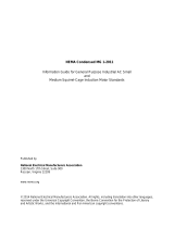
Cast aluminum alloy shoe base with aluminum alloy bolt
covers or base cover dependent upon base type.
2
...
Flush reinforced 2 3/8" x 4 1/2" for 4" shafts. Hand hole
assembly with internal reinforcing frame. 3" x 5" for 5" and
6" shafts, 4" x 6" for 7", 8", 10" shafts. Ground lug located
opposite hand hole opening drilled & tapped for 3/8"
16NC-2 grounding screw.
3
...
Tapered aluminum lighting shaft with polished finish.
4
...
Drilled or Tenon (specify).
5
...
Anchor bolt per ASTM A576 with (1) nut, (1) flat washer,
and (2) shims. Nuts, washers and threaded portion of bolt
are hot dip galvanized.
SPECIFICATION FEATURES
FOUR BOLT ANCHORAGE [See ordering information]
BC=Bolt Circle
BP=Bolt Projection
AB=Bolt Dimensions
D=Bolt Diameter
H=Bolt Dimensions
FINISH COLORS [See ordering information. Other finish colors available.]
B=Clear Anodized
C=Dark Bronze Anodized
D=Black Anodized
E=Medium Bronze Anodized
F=Dark Bronze Powder Coat
V=Grey Powder Coat
W=White Powder Coat
X=None (natural aluminum)
Y=Black Powder Coat
10'—40' MOUNTING HEIGHT
RTA ROUND TAPERED ALUMINUM
POLES
MH
(mounting height)
Base View
18"
handhole
1
2
3
4
AB
BP
BC
H
D
5
WARNING: THE USE OF UNAUTHORIZED ACCESSORIES SUCH AS BANNERS, SIGNS OR PENNANTS FOR WHICH THE POLE WAS NOT DESIGNED FOR VOIDS THE COOPER LIGHTING
WARRANTY AND MAY RESULT IN POLE FAILURE CAUSING SERIOUS INJURY OR PROPERTY DAMAGE. COOPER LIGHTING'S POLE WARRANTY IS ALSO VOIDED IF
LUMINAIRE IS NOT INSTALLED AT TIME OF POLE INSTALLATION.

STREETWORKS Outdoor Lighting Solutions 185Cooper Lighting
ROUND TAPERED ALUMINUM POLES
Shaft Mounting Fixture No. & Accessories
Dia. Wall Height Base Mounting Location Arm (Vibration
Round Tapered Aluminum (at base) Thickness (ft.) Type Finish & Type of Arms Lengths Damper)
RT A 5 M 20 N A X X XV
Base Bolt
Mtg. Wall Dia. or Shaft Bolt Circle Anchor Bolt Net. Max. Fixture
Height Catalog Thickness Square Taper Proj. Dia. D x AB x H Wt. EPA (Sq. Ft.)
2, 4
EPA (Sq. Ft.)
2, 4
Load Include
(Ft.) Number
3
(In.) (In.) (In.) (In.) (In.) (In.) (Lbs.) At Pole Top 18" Above Pole Top Bracket (Lbs.)
MH S B BP BC AB 70 80 90 100 70 80 90 100
10 RTA4T10NA .125 9 1/4 4 x 3 1 7/8 6 3/4 3/4 x 17 x 3 22 14.9 11.0 8.4 6.6 12.6 9.4 7.1 5.6 100
12 RTA4T12NA .125 9 1/4 4 x 3 1 7/8 6 3/4 3/4 x 17 x 3 25 11.3 8.2 6.1 4.6 9.8 7.2 4.3 4.0 100
15 RTA4T15NA .125 9 1/4 4 x 3 1 7/8 6 3/4 3/4 x 17 x 3 30 7.7 5.4 3.8 2.7 6.8 4.8 3.4 2.4 100
15 RTA5T15NA .125 10 1/2 5 x 3 1 7/8 7 3/4 3/4 x 17 x 3 33 13.6 9.9 7.4 5.6 12.2 8.8 6.6 5.0 100
18 RTA5T18NA .125 10 1/2 5 x 3 1 7/8 7 3/4 3/4 x 17 x 3 39 9.9 6.9 4.9 3.6 9.0 6.3 4..5 3.3 100
18 RTA6L18AA .156 10 1/4 6 x 4 2 1/8 9 3/8 3/4 x 17 x 3 57 19.9 14.6 11.1 8.8 18.2 13.3 10.1 8.0 100
20 RTA5T20NA .125 9 1/4 5 x 3 1 7/8 8 1/2 3/4 x 17 x 3 43 8.0 5.4 3.7 2.5 7.3 4.9 3.4 2.3 100
20 RTA6L20AA .156 10 1/4 6 x 4 2 1/8 9 3/8 3/4 x 17 x 3 64 16.5 11.9 8.9 7.0 15.6 10.9 8.2 6.4 150
25 RTA6L25AA
1
.156 10 1/4 6 x 4 2 1/8 9 3/8 3/4 x 17 x 3 81 10.4 7.8 5.0 3.7 9.7 6.6 4.6 3.5 150
25 RTA8L25AA
1
.156 11 5/8 8 x 4 1/2 2 3/4 11 1/2 1 x 36 x 4 106 23.3 17.2 13.2 10.4 21.7 16.0 12.3 9.7 200
30 RTA7L30AA
1
.156 10 5/8 7 x 4 2 3/4 10 1/2 1 x 36 x 4 108 11.0 7.5 5.3 4.0 10.4 7.1 4.0 3.7 150
30 RTA8L30AA
1
.156 11 5/8 8 x 4 1/2 2 3/4 11 1/2 1 x 36 x 4 117 16.4 11.8 8.9 6.9 15.4 11.1 8.4 6.5 200
30 RTA0L30AA
1
.156 14 1/2 10 x 6 2 7/8 14 1/2 1 x 36 x 4 152 30.5 22.8 17.6 13.8 28.8 21.6 16.6 13.0 250
35 RTA8L35AA
1
.156 11 5/8 8 x 4 1/2 2 3/4 11 1/2 1 x 36 x 4 140 11.5 7.9 5.8 4.3 10.9 7.5 5.5 4.1 150
35 RTA0L35AA
1
.156 14 1/2 10 x 6 2 7/8 14 1/2 1 x 36 x 4 180 23.3 17.3 13.1 10.0 22.2 16.4 12.5 9.5 200
40 RTA8M40AA
1
.188 11 5/8 8 x 4 1/2 2 3/4 11 1/2 1 x 36 x 4 210 11.0 7.5 5.3 3.9 10.6 7.1 5.1 3.7 100
40 RTA0L40AA
1
.156 14 1/2 10 x 6 2 7/8 14 1/2 1 x 36 x 4 209 17.9 13.0 9.6 7.1 17.2 12.5 9.2 6.8 150
NOTES: 1 Factory installed vibration dampeners. 2 Where higher EPA/wind speed capability or mounting height is required, other shaft dimensions and/or wall thickness are available. consult Cooper Lighting representative for pricing and lead times. The above
E.P.A. capacities are based on loading from (1994) and pole drag coefficients from (2001) American Association of State Highway and Transportation Officials Specification. 3 Catalog item includes one set of anchor bolts, single nuts and (2) leveling
shims. 4 EPAs based on shaft properties with wind normal to flat. EPAs calculated using base wind velocity as indicated plus 30% gust factor.
MACHINING FOR RECTANGULAR ARMS [Add as suffix]
Designation Designation Designation Quantity
Letter & Number Letter & Number Letter & Number & Location
M1 E1 Z1 Single
M2 E2 Z2 2 @ 180°
M3 E3 Z3 3 @ 120°
M4 E4 Z4 4 @ 90°
M5 E5 Z5 2 @ 90°
NOTES: Refer to Fixture Drilling Options on page 160.
ACCESSORIES [Order separately]
C=Convenience Outlet
E=GFI Convenience Outlet
F=Vibration Pad
G=Ground Lug
V=Vibration Damper
B=Base Cover (“A” Base Only)
MOUNTING OPTIONS [Add as suffix]
Fixed Tenon Designation O.D. Length
Number (In.) (In.)
1 2 3/8 3 1/2
2 2 3/8 4
534
446
7/8''
2 13/16''
3/4'' dia.
hole
(2) 3/8"
dia. holes
3 7/8''
DRILLING PATTERN
Type “M” [RCL, Landau, Galleria and Vision] Type “E” [Concourse III] Type “Z” [Credenza and Cirrus]
3/4'' dia.
hole
(2) 5/8''
dia. holes
2 7/16''
2 5/16''
4 7/8''
O.D.
LENGTH
9/16" [14mm]
dia. hole (3)
4 7/8" [124mm]
4" [102mm]
2 7/16" [62mm]
ORDERING INFORMATION
SAMPLE NUMBER: RTA5M20NA
STANDARD BASE [Round Aluminum Pole Only]
TYPE A TYPE N [Standard with base cover]
6", 7", 8" or 10" 4", 5", or 6"
NOTE: Specifications and dimensions subject to change without notice.
NOTE: Bolt location relative to hand
hole. Refer to pg. 160 for drilling
information.
/