Current HLOI0022 Operating instructions

Type
Operating instructions

Current HLOI0022 is a high-quality, versatile lighting controller designed to provide precise lighting control for a variety of applications. With its advanced features and user-friendly interface, the HLOI0022 offers a powerful solution for managing and customizing your lighting setups. This lighting controller enables you to create dynamic light shows, adjust color temperatures, and set schedules for automated lighting changes. Its compatibility with various lighting fixtures and protocols makes it a versatile choice for both residential and commercial use.

Current HLOI0022 is a high-quality, versatile lighting controller designed to provide precise lighting control for a variety of applications. With its advanced features and user-friendly interface, the HLOI0022 offers a powerful solution for managing and customizing your lighting setups. This lighting controller enables you to create dynamic light shows, adjust color temperatures, and set schedules for automated lighting changes. Its compatibility with various lighting fixtures and protocols makes it a versatile choice for both residential and commercial use.

CURRENT LIGHTING / POLE VIBRATION APPLICATION GUIDE
As an industry leader in light pole design and manufacturing, Current is committed to providing information to help
designers avoid wind induced pole vibration. This paper presents a practical guide for recognizing and minimizing
the potential damaging eff ects of wind on light poles.
Defi ning Wind-Induced Vibration
Wind induced pole vibration is partially defi ned, or characterized, by the type of movement observed in
a pole system.
Two common types of pole vibration are:
FIRST MODE (Harmonic) VIBRATION SECOND MODE (Resonance) VIBRATION
Figure 1: First and Second Mode Pole Vibration
FIRST MODE VIBRATION is characterized by a side to side movement that has a maximum displacement at
the top of the pole. This behavior may be referred to as “sway”. The frequency of movement is about 1 cycle per
second or less. Because the vibration frequency is comparatively small, the onset of material fatigue will take
longer than poles exhibiting higher modes of vibration.
SECOND MODE VIBRATION is characterized by a symmetric oscillation at or near the midpoint of the pole
shaft. The oscillation frequency typically ranges from 3-6 cycles per second. Second mode vibration occurs when
air moving across a pole reaches “lock-in” velocity. At “lock-in” velocity, Vortex Shedding produces alternating
transverse forces that oscillate the pole at one of its natural frequencies. The onset of fatigue cracking or structural
failure may occur quickly under such conditions.
VORTEX SHEDDING is the phenomenon caused by a steady, constant velocity wind moving across a slender,
exible object, like a pole. Vortices forming on the sides of the pole create localized, pockets of low pressure.
These pockets alternate, creating alternating forces that act on the pole perpendicular to the wind direction.
Figure 2: Vortex Shedding simulation about a cylinder demonstrating alternating low pressure zones in wake
EFFECTS OF WIND INDUCED VIBRATION
The eff ects of wind induced vibration will vary as they are infl uenced by many factors; including site features, pole
design and shape, and wind conditions. Wind induced vibration can lead to reduced performance in the pole
systems and may result in structural failure.
currentlighting.com
© 2022 HLI Solutions, Inc. All rights reserved. Information and specifications subject to change
without notice. All values are design or typical values when measured under laboratory conditions.
Airports – Turbulent air from aircraft and localized fl at
areas absent of objects to break the wind currents
Bridges and Parking Decks – Flat, elevated structures in
open areas can also transfer vibration generated by
moving vehicles or move on their own as a result for
vortex shedding about its structural supports
Figure 7: Example of parking deck with pole mounted luminaires.
Local Conditions - Site specifi c terrain and conditions
Figure 4: Open terrain examples in central US
Regional Geography – Expansive, fl at areas with little
natural or man-made wind breaks as common in the
upper mid-west, plains states, and some coastal
regions.
Environmental Conditions that Increase Risk
Environmental variables like wind conditions, terrain, landscape, and site structures greatly infl uence
how wind will aff ect pole systems. This partial list includes application attributes that may facilitate wind
induced pole vibration.
Mountains, Foothills, Cityscapes – Areas with steady air
currents or areas with natural or man-made features that
alter wind patterns
Figure 5: Illustration of wind pattern changes caused by structures
Figure 6: Jet blast
CURRENT LIGHTING / POLE VIBRATION APPLICATION GUIDE
Flat, Open Terrain – Localized fl at areas with little or no
wind breaks (i.e. large parking lots, large fi elds, top of
parking structures, causeways)
Figure 3: Coastal Locations
Fig. 3
Fig. 4
Fig. 5
Fig. 6
Fig. 7
Fig. 8
Figure 8: Unique application.
currentlighting.com
© 2022 HLI Solutions, Inc. All rights reserved. Information and specifications subject to change
without notice. All values are design or typical values when measured under laboratory conditions.
Design Factors To Consider
Pole selection can also contribute to the potential for wind induced vibration. Relevant design attributes are:
Loading – Luminaire size (EPA), luminaire weight, luminaire quantity, and luminaire orientation will infl uence the behavior of
the pole and its susceptibility to vibration. Loads that exceed the design limits of the pole may result in structural failure. Also
problematic, very small loads and zero loaded poles (lightly damped) may be prone to vibration.
Height – Pole height governs the amount of defl ection a pole will move and the size of the moment generated at the pole base.
An increase in height will increase both values, making it more susceptible to wind induced vibration.
Wall Thickness – Pole wall thickness aff ects the rigidity of the pole. Increasing the wall thickness will reduce its fl exibility and
reduce the eff ects wind has on the system.
Material – Common pole materials include steel, aluminum, concrete, fi berglass, cast iron and wood. Material properties vary
between material types. Steel and aluminum are very common materials used in light pole manufacturing. Of the two types,
steel has higher strength of material properties than aluminum.
Shape – Pole shape (cross section geometry) also infl uences pole performance because aerodynamic characteristics change
by shape. When comparing square poles to round poles, square poles have higher drag coeffi cients. Square poles may also
have more complex, asymmetric fl ow patterns around the pole. This is especially true for winds approaching off angle from the
either the fl at surfaces or corners.
Recommendations
Evaluate risk - Inspect site conditions and evaluate the risk of problematic wind conditions.
Mitigate risk through pole selection -
• Avoid poor damping conditions caused by under loading poles. Poles should not be installed without the luminaires they
are designed to support.
• Strengthen or stiff en the pole via material selection (i.e. choose steel over aluminum), increase wall thickness, increase the
cross sectional size, and/or minimize height.
• Consider round tapered poles.
Increase Damping - The uses of factory or fi eld installable damping devices o er an economical option for minimizing
destructive vibration. Most dampers reduce the amplitude of mechanical vibrations by adding mass that moves at a
diff erent rate than the shaft of the pole. Some dampers also change the natural frequency of the pole by moving the
excitation frequency, thereby changing the critical velocity and the forces generated by vortex shedding.
First Mode Dampers
First Mode vibration dampers are designed to reduce the amplitude of pole top defl ection caused by First Mode vibration.
Current off ers a First Mode vibration damper (Q41) that is factory assembled, painted to match, and ready for eld install.
It is designed for 4”, 5”, and 6” square aluminum and steel lighting poles.
Figure 9: Simulated fl ow about a straight square
cylinder at various wind approach angles
Taper – Taper can also change the aerodynamic characteristics of the pole, shifting the critical wind velocity that causes
Second Mode vibration.
Figure 10: First Mode Vibration Damper (Q41)
CURRENT LIGHTING / POLE VIBRATION APPLICATION GUIDE
currentlighting.com
© 2022 HLI Solutions, Inc. All rights reserved. Information and specifications subject to change
without notice. All values are design or typical values when measured under laboratory conditions.
Second Mode Dampers
Second Mode vibration dampers are designed to alter the natural frequency at which the pole will resonate, reducing the pole
movement and the onset of material fatigue caused by wind. Both fi eld installable and factory installed Second Mode vibration
dampers are available.
Current off ers two types of Second Mode vibration dampers.
Perform and Record Pole Maintenance
An important tool to reduce risk and the eff ects of wind induced vibration is a properly implemented pole maintenance plan.
Inspections should be conducted on a routine basis, starting at the time of installation, week 1, month 1, month 6, and then
annually thereafter. It is also advisable to check installations for changing pole movements, damage, or signs of stress after a
major wind event or changes to the site that may aff ect wind patterns. Site changes may include new building structures, new
landscape plantings, or growth of existing landscaping. Inspecting for the eff ects of vibration is a very important part of any proper
maintenance plan. If any eff ect exists, the pole can be compromised in a short period of time. The results can be as severe as
structural failure. Signs of vibration can be observed following this basic guideline, special training or certifi cation is usually not
required.
• Observe pole movement during windy conditions. Excessive defl ection, rapid oscillation at the shaft midpoint, or audible
thumping of electrical conductors in the pole may be indications of pole vibration.
• Low torque values on anchor bolts.
• Loose or missing parts at the luminaire and/or pole top are an early indication that the pole may be vibrating in
application. Missing pole caps, loose HID sockets, and prematurely failing HID lamps are a few examples. Correct or
replace as necessary.
• Look for signs of rust and corrosion above the pole base plate weld and about the hand hole. Corrosion may
indicate an area of fatigue. If present, remove the corrosion and wipe clean. Hairline cracks just above the pole base
plate weld may indicate shaft material fatigue. An inexpensive die may be used to aid in detection.
• For square poles, inspect the corners near the base plate in a similar manner.
• Review the entire pole shaft for signs of fi nish deterioration.
If any indications of fatigue exist, a qualifi ed and experienced structural engineer should be consulted, the aff ected pole should
be taken down immediately, and an inspection should be performed for the entire site. If vibration has or is occurring, but the pole
is deemed to be structurally sound, mitigation steps should be taken immediately by adding dampers and monitoring the pole
behavior. If vibration continues after dampers are added, an alternate pole shape or construction should be considered.
Pole Warranty
Wind induced vibration is a naturally occurring phenomena that may lead to structural failure of poles. Such a failure is not an
indication of inferior design, material, or craftsmanship. As such, Currents’s warranty does not apply to and Current shall have no
liability for any failure of the products or damage due to fatigue failure or similar phenomena resulting from induced vibrations,
harmonic oscillation or resonance associated with movement of air currents around the product.
Recommendations Ctd...
Interior Canister (Q42) vibration dampers feature an internal cylinder that houses a
cushioned, weighted rod pendulum. This device moves in the opposite direction of the
shaft, disrupting vibrations. The impact of the pendulum against the cylindrical housing
may be audible under certain conditions. This type of damper is factory installed.
Serpentine Tube (special order) vibration dampers are fi eld installed through hand
holes. These devices wrap around the inner surface of the pole shaft, are free
standing, and reduce motion.
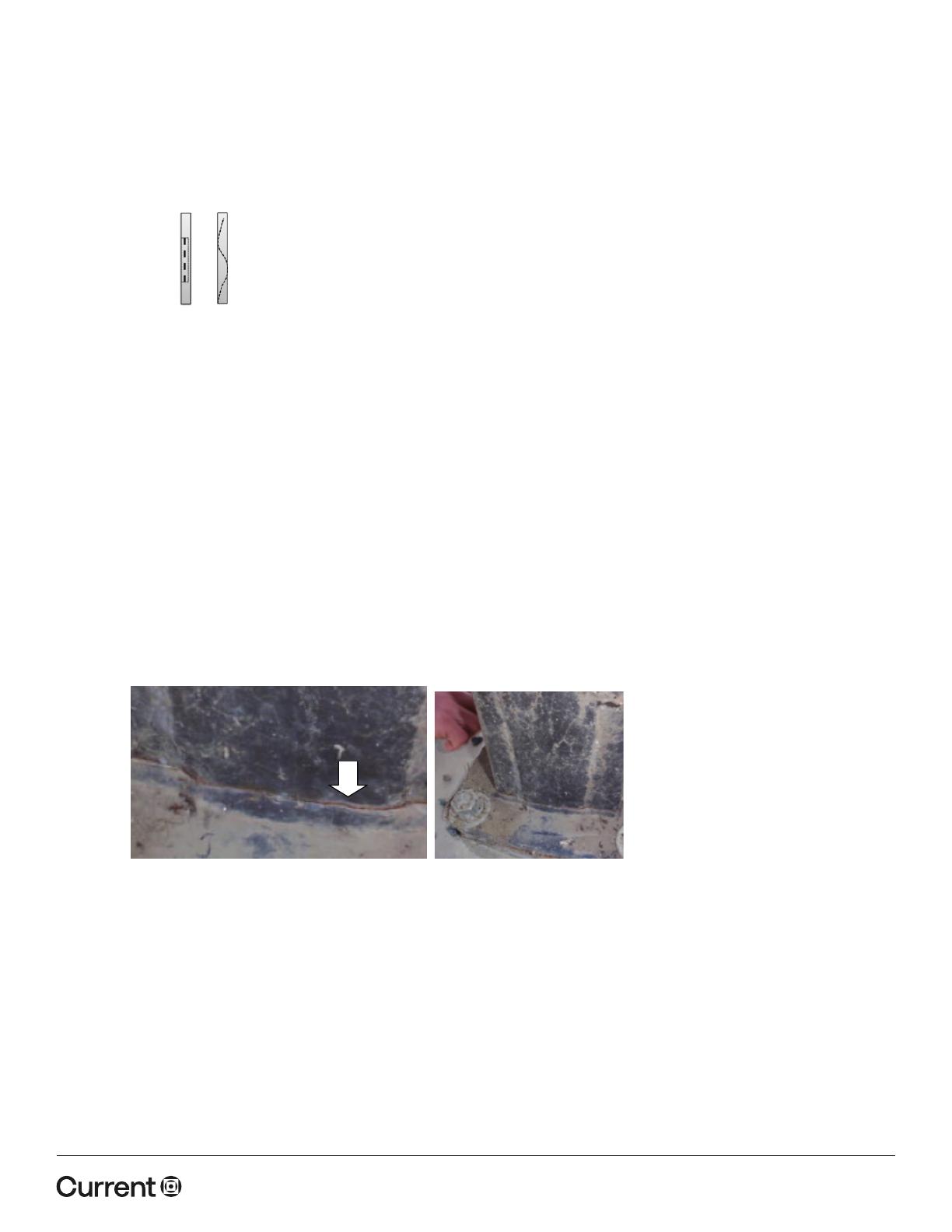
Figure 11: Canister and tube dampers
Figure 12: Example of fatigue cracking at
the base plate weld
CURRENT LIGHTING / POLE VIBRATION APPLICATION GUIDE
currentlighting.com
© 2022 HLI Solutions, Inc. All rights reserved. Information and specifications subject to change
without notice. All values are design or typical values when measured under laboratory conditions.
  • Page 1 1
  • Page 2 2
  • Page 3 3
  • Page 4 4

Current HLOI0022 Operating instructions

Type
Operating instructions

Current HLOI0022 is a high-quality, versatile lighting controller designed to provide precise lighting control for a variety of applications. With its advanced features and user-friendly interface, the HLOI0022 offers a powerful solution for managing and customizing your lighting setups. This lighting controller enables you to create dynamic light shows, adjust color temperatures, and set schedules for automated lighting changes. Its compatibility with various lighting fixtures and protocols makes it a versatile choice for both residential and commercial use.

Ask a question and I''ll find the answer in the document

Finding information in a document is now easier with AI