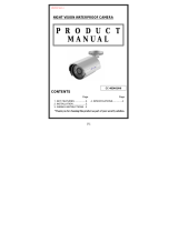
Eneo GLC-1702 Installation And Operating Instructions Manual

Category
Security cameras
Type
Installation And Operating Instructions Manual

This manual is also suitable for

1
Installations- und Betriebsanleitung
Wetterfeste Tag/Nacht-Netzwerkkamera 1/3”
GLC-1701/IR, GLC-1702
Installation and Operating Instructions
Weather Proof Day-Night Network Camera 1/3”
GLC-1701/IR, GLC-1702
Instructions d’installation et d’utilisation
Caméra réseau jour/nuit à l’épreuve des intempéries 1/3”
GLC-1701/IR, GLC-1702
Instrucciones de instalación y manejo
Cámara de red diurna-nocturna impermeabilizada 1/3”
GLC-1701/IR, GLC-1702
2
www.videor.com
Montage- und Betriebsanleitung
Installation and Operating Instructions
Mode d’emploi
Instrucciones de manejo
Inhalt
1. Sicherheitshinweise ..............................................3
2. Allgemeine Beschreibung ......................................
4
3. Lieferumfang .........................................................
4
4. Bezeichnungen und Bedienelemente .....................
5
4.1 Außen ...................................................................
5
4.2 Innen .....................................................................
6
5. Installationsanweisungen ......................................
7
5.1 Spannungsversorgungsanschlüsse ........................
7
5.2 Montage ................................................................
7
5.3 Einstellung des Bildausschnitts ..............................
8
6. Technische Daten ..................................................
9
7. Bohrplan .............................................................
39
8. Maßzeichnungen .................................................
39
Sommaire
1. Consignes de sécurité .........................................21
2. Description générale ...........................................
22
3. Contenu de la livraison ........................................
22
4. Descriptions et éléments de commande ..............
23
4.1 Extérieur
..............................................................23
4.2 Intérieur ..............................................................
24
5. Consignes d’installation .......................................
25
5.1 Fiches d’alimentation ..........................................
25
5.2 Montage ..............................................................
25
5.3 Réglage du cadrage ............................................
26
6. Caractéristiques techniques ................................
27
7. Plan de perçage ..................................................
39
8. Croquis
................................................................39
Contents
1. Safety Instructions ...............................................12
2. General Description .............................................
13
3. Supplied Items ....................................................
13
4. Part Names and Controls .....................................
14
4.1 External ...............................................................
14
4.2 Internal ................................................................
15
5. Installation Instructions ........................................
16
5.1 Power Supply Connections ..................................
16
5.2 Mounting .............................................................
16
5.3 Setup of the Image Sector ...................................
17
6. Specifications .....................................................
18
7. Drilling Plan .........................................................
39
8. Dimensional Drawings .........................................
39
Indice
1. Instrucciones de seguridad ..................................30
2. Descripción general .............................................
31
3. Contenido ............................................................
31
4. Nombres de las partes y mandos
.........................32
4.1 Exterior ...............................................................
32
4.2 Interior ................................................................
33
5. Instrucciones de instalación ................................
34
5.1 Enchufes de corriente ..........................................
34
5.2 Montaje ...............................................................
34
5.3 Ajuste de la sección de imagen ..........................
35
6. Especificaciones ..................................................
36
7.
Plano de taladrado ..............................................39
8. Medidas ..............................................................
39
HINWEIS: Bitte beachten Sie auch die beiliegende Betriebsanleitung für das Ethernet Server Modul !
NOTE: Please pay attention also to the enclosed manual for the Ethernet server module !
REMARQUE: Veuillez noter aussi le mode d’emploi ci-inclus pour le module du serveur Ethernet,
s’il vous plaît !
NOTA: Por favor, tenga en cuenta también en las instrucciones adjuntas del módulo de servidor Ethernet !
12
1. Safety Instructions
Read these safety instructions and the operation manual first before you install and commission the camera.
Keep the manual in a safe place for later reference.
Protect your camera from contamination with water and humidity to prevent it from permanent damage.
Never switch the camera on when it gets wet. Have it checked at an authorized service center in this case.
Never operate the camera outside of the specifications as this may prevent the camera functioning.
Do not operate the cameras beyond their specified temperature, humidity or power ratings.
Operate the camera only at a temperature range of -30°C to +50°C and at a humidity of max. 85%.
To disconnect the power cord of the unit, pull it out by the plug. Never pull the cord itself.
Pay attention when laying the connection cable and observe that the cable is not subject to heavy loads, kinks, or
damage and no moisture can get in.
The warranty becomes void if repairs are undertaken by unauthorized persons. Do not open the camera housing.
Never point the camera towards the sun with the aperture open. This can destroy the sensor.
Installation, maintenance and repair have to be carried out only by authorized service centers.
Before opening the cover disconnect the unit from mains input.
The fitter is responsible for the system of protection being followed in accordance with the technical data, e.g. by
sealing of the cable outlet with silicone.
Contact your local dealer in case of malfunction.
Only use original parts and original accessories from Videor E. Hartig GmbH.
The camera is equipped with an automatic gain control (AGC) which increases the sensitivity at low light levels.
Noisy pictures at these conditions are quite normal.
Pictures including bright spotlights will cause perhaps vertical lines (smear) or soft edges (blooming) on the
monitor display. This happens most probably in automatic shutter mode (ESC).
This is not a defect but an effect caused by the CCD sensor.
Be sure to put a silica-gel bag into the housing to avoid humidity due to temperature variance between inner and
outside of housing
Do not use strong or abrasive detergents when cleaning the dome. Use a dry cloth to clean the dome surface.
In case the dirt is hard to remove, use a mild detergent and wipe gently.
During assembly, care must be taken to ensure that existing seals are correctly inserted and are not
displaced as a result of assembly.
You must not continue to use damaged seals.
ATTENTION: The fastening screws (10) may be completely tightened only then if the accurate position
of the camera is adjusted. If the camera housing on the mount bracket is moved, after the fixing
screws are firm, leakage in the housing can develop.
NOTE: This is a class A digital device. This digital device can cause harmful interference in a residential area;
in this case the user may be required to take appropriate corrective action at his/her own expense.
13
2. General Description
Weatherproof Camera with Swivel Head Bracket
1/3” D&N CCD Camera with DC Lens F1.2/3.8-9.5mm
Removable IR Cut Filter
High Speed Shutter Control (ESC) –
(GLC-1701/IR, Art. No. 96092)
High and Low Speed Shutter Control (ESC/DSS) –
(GLC-1702, Art. No. 96093)
Sensitivity Enhancement: 32x max. (DSS function) –
(only GLC-1702, Art. No. 96093)
IR Illumination by 15 integrated 850nm LED’s –
(only GLC-1701/IR, Art. No. 96092)
Dynamic (Light) Intensity Control (DIC) –
(only GLC-1701/IR, Art. No. 96092)
Back Loght Compensation (BLC)
Integrated Web Server: 10Base-T/100Base-TX
MJPEG and MPEG-4 Compression (GL Series)
Viewer for Monitoring, Recording and Configuration
Email (FTP), GPIO Notification in Case of an Alarm
Supply Voltage: 12VDC
Fully Hidden Cable Routing
Protection Rating IP67
3. Supplied Items
1x Weatherproof day/night network camera
1x Installation and operating instructions
1x 3mm L-Hex wrench
3x Mounting screws
1x Silicagel bag
14
4. Part Names and Controls
4.1 External
(1) Housing body
(2) 15 IR LEDs (GLC-1701/IR only)
(3) Lens distance ring (GLC-1701/IR only)
(4) Lexan window
(5) Front cover
(6) Neck
(7) Ball housing
(8) Rear cover screws, 2x (not visible)
(9) Rear cover
(10) Neck fastening screws, 3x
(11) Screws for installation kit, 3x
(12) Mount base
(13) Base plate assembly kit – (not visible)
(14) Panel assembly kit
(15) Connection cable
1
2
3
4
5
6
7
8
9
10
12
13
14
11
15
16 1817 19
(16) RJ-45 Connection
(17) Power input 12VDC
(18) Video output
(19) Alarm input
15
4.2 Internal
GLC-1702GLC-1701/IR
(a) Lens hood
(b) Focus adjustment knob
(c) Zoom adjustment knob
(d) Iris level adjustment potentiometer
(e) Infrared LED
(f) IR LED board ASS’Y
(g) Function switch
(h) Power supply board
(i) Ethernet server module
Switch Description – GLC-1701/IR
SW Name ON (down) OFF (up) Rem..
2
ELC/ALC ELC: Elec. shutter mode ALC: Auto iris lens mode
3
BLC Back light compensation ON Back light compensation OFF
5
FL Flickerless ON
Shutter is fixed to 1/120sec.
Flickerless OFF
(at 50Hz mains frequency)
*)
7
Day-Night IR cut filter OUT (automatic) IR cut filter ON (for colour operation)
f
g
d
c
b
e
a
h
i
f
d
c
b
e
a
(a) Focus adjustment knob
(b) Zoom adjustment knob
(c) Iris level adjustment potentiometer
(d) Function switch
(e) Power supply board
(f) Ethernet server module
*): Flickerless mode is useful in areas where AC mains is 50Hz and TV system is NTSC such like Japan
or AC is 60Hz and TV system is PAL to reduce the flicker under the florescent lights.
When FL is set to ON, the low light sensitivity is down about 30%.
16
Switch Description – GLC-1702
Name ON (down) OFF (up) Rem.
1
D/N
DSS is activated and sensitivity is raised
if the light intensity is reduced.
DSS switched OFF and camera behaves
like a normal camera.
2
L/H Digital slow shutter with x16 image store Digital slow shutter with x32 image store
5. Installation Instructions
Make sure the power is removed before installation.
5.1 Power Supply Connections
Camera can be operated with 12VDC only.
DC plug for all 12VDC cameras
5.2 Mounting
5.2.1 Installation on Wall
1) Loosen three neck fastening screws (10) a little (but not completely) so that camera body can move.
2) Secure the mount base (12) with screws supplied to the wall or ceiling.
Make sure that the cable is routed safely not to be damaged by the mount base (12) (see gap).
3) Separate the housing body (1) by loosening two rear cover screws (8) and place it at a safe area.
Make sure that the inside of the housing body (1) should not be contaminated by dust or liquid.
4) Set the camera direction roughly and fasten three neck fastening screws (10).
5) Apply the power to the camera.
6) Set the zoom (d) and focus (c) (see 5.3).
After setting zoom and focus, secure the knobs (d) and (c).
7) Adjust the parameters by using DIP switch setting.
8) Remove the power again.
9) Repeat step 1).
This step is a preparation for an easy assembling for step 10).
17
10) Replace the existing silica-gel bag with new one after setting camera control parameters.
11) Assemble the housing body (1) to the rear cover by tighten two rear cover screws (8).
When securing two rear cover screws (8), do not complete one at a time and another next.
Both screws are recommended to be tightened evenly a little at a time in turn.
12) Trim the camera before the final secure and completely tighten three neck fastening screws (10).
5.2.2 Installation on Ceiling
The camera is now upside down, i.e. the module and housing must be turned 180°.
For ceiling installation please contact Videor in advance. They will modify the camera before shipping.
5.2.3 NOTE - Silicagel bag
As it is not always possible to avoid a situation where a certain amount of moisture remains in the opened casing, we
recommend using the enclosed bag of silicagel in such cases. It must be ensured that the gel is used appropriately,
i.e. opening the protective film too soon can lead to the silicagel becoming saturated in a very short period of time,
thereby making it ineffective.
1. Before inserting the silicagel pack, please remove the aluminium protective sleeve around the pack, as the
silica gel is only effective without the aluminum protective sleeve.
2. Insert the pack between the back of the casing and the camera holder.
3. The silica gel retains the residual moisture that accumulated in the casing during assembly in a moist climate.
5.3 Setup of the Image Sector
Focus and focal length should be adjusted only by authorized persons.
Pull off the camera housing.
Power up the camera and connect a monitor.
Open the zoom handle (d) (see page 18). Turn the ring to adjust the zoom setting.
Focus is adjusted by turning the focus handle (c).
Tighten both handles (c) + (d) when adjustment is done. Close the housing.
NOTE: For a precise adjustment of cameras installed outside it is recommended to place a ND (Neutral
Density) filter in front of the lens while settings are done. This opens up the iris and allows a setting
which is constant at changing light conditions due to the narrower depth of field.
18
6. Specifications
Type GLC-1701/IR GLC-1702
Art. No. 96092 96093
Series
W3 Plug & Play
System
Day & night
Video standard
CCIR/PAL
Sensor size
1/3”
Imager
CCD, Sony Super HAD II Interline Transfer
Synchronization
Internal
Sensitivity (at 50% video signal)
0.2Lux at colour, 0.06Lux (B&W).
Videor measurement result at F1.2
0.2Lux at colour, 0.025Lux (B&W).
Videor measurement result at F1.2
Horizontal resolution
540 TVL 520 TVL
Active picture elements
440,000, 752(H) x 582(V)
Automatic gain control (AGC)
28dB max.
High-speed shutter (ESC)
1/50 ~ 1/100,000sec.
Digital Noise Reduction (DNR)
no
Integration rate
no yes
White balance (ATW)
2000 ~ 8000K, Automatic tracking
Backlight compensation
BLC, Center weighted (On/Off switchable)
IR cut filter
Switchable
Activity detection
yes, 96 zones, 5 levels sensitivity (MJPEG)
Picture adjustments
Colour, brightness, contrast (via Network)
External adjustments
4 DIP switches for: ALC/ESC, BLC
On/Off, Flickerless On/Off,
Day/Night: Auto/colour. Level for DC
voltage controlled iris
DSS On/Off, DSS 8x/16x, Level
control for DC controlled iris
Video outputs (type)
CVBS
Video outputs
1Vp-p, (C)VBS, 75ohms, BNC
Audio support
no
Alarm inputs
1
Alarm outputs
1
Alarm handling
Email (FTP), GPIO output. SMPT recording
Internal storage
no
Compression standard
MJPEG, MPEG4
Resolution max.
720 x 576
MPEG4 Quality
5 fixed levels and customized Bitrate (from 64kBps ~ 8MBps)
Transmissiooon rate (Network)
up to 2 MB/sec.
Image transm. rate max.
25 B./sec.
19
Type GLC-1701/IR GLC-1702
Art. No. 96092 96093
Frame rate
25 / 24 /15 / 5 ips
Vetwork connection
RJ-45
Ethernet interface
10Base-T, 100Base-TX
Network protocols
TCP/IP, DHCP, HTTP, FTP, SMTP, SNTP, DDNS, UPnP, PPPoE
Lens type
Varifocal
Lens
F1.2/F2.0 ~360/3.8 ~ 9.5mm with galvanometer controlled iris
Lens mount
Integrated lens
Aspherical technology
yes
Focal length
3.8 mm - 9.5 mm
Horizontal angle of view
74.2° - 30°
Iris control
DC
MOD (Minimum object distance)
0.15m
Filter screw size
Not available
Illumination
15 LEDs 850nm. Integrated light
sensor for On/Off switching of the
illumination
Illumination range
Approx. 15m (at a good light
reflexion and 40% video signal)
Hidden cable management
yes
Cable connection
Video (BNC), 12VDC (DC jack), RJ-45 (8 pin), Alarm in (2 wire open end cable)
Serial interfaces
no
Access
8 Users simultaneous support
Software upgrade
HTTP or FTP
Password protection
yes, 3 password levels
PTZ Support
no
Supply voltage
12VDC, (9~18VDC)
Power over Ethernet
no
Power consumption
6watts 4.2watts
Temperature range (Operation)
-30°C ~+50°C
Housing
Aluminium with clear polycarbonate window, outdoor
Mounting
Wall mount (bracket included)
Colour (housing)
Pantone 7541
Housing material
Aluminium
Protection rating
IP67
Integrated wall mount
yes
Sunshield
no
20
7. Drilling Plan
See page 39
8. Dimensional Drawings
See page 39
Optional Accessories
Art. No. Type Description
70535 VT-PS12DC-8
Plugable PSU, 100-240V/12VDC-1,0A, stabilized, with DC plug
77773 VT-PS12DCDT1
Power Supply Unit 12VDC/1,0A, regulated, desktop version,
1.8m DC-cable each with open ends
70543 VT-PS12DC-10
Plugable AC/DC Adapter 100-240V/12VDC- 2.5A, stabilized, Continent & UK Mains
plug-in
76003 ZELARIS_IP VC
Client Version for Zelaris_IP Server for one workstation
76051 ZELARIS_IP V04
Video Management Software for standalone systems, basic version, 4 cameras
76047 ZELARIS_IP HL-B
Control Room Client Software, basic version, Up to max. 1024 channels
76058 ZELARIS_IP HL-E
Extension for Control Room Client for further up to 1024 channels max.
76053 ZELARIS_IP S04
Server/Client Video Management Software, basic version, 4 camera server license
76056 ZELARIS_IP S04E
Software Extension for Zelaris_IP S04 for further 4 cameras, max. 64 cameras
Type GLC-1701/IR GLC-1702
Art. No. 96092 96093
Window heater
no
Clear Shield
no
Dimensions
See drawing
Weight
785g
Management Software Support
GL-Manager, Zelaris IP, Aimetis - Symphony, NetAvis,
Milestone XProtect Corporate
Certificates
CE
40
Technische Änderungen vorbehalten.
Technical changes reserved.
Nous nous réservons toutes modifications techniques.
Sujeto a modificaciones técnicas.
© Copyright by VIDEOR E. Hartig GmbH 11/2009
eneo
®
ist eine eingetragene Marke der Videor E. Hartig GmbH
Vertrieb ausschließlich über den Fachhandel.
eneo
®
is a registered trademark of Videor E. Hartig GmbH
Exclusive distribution through specialised trade channels only.
eneo
®
est une marque propriété de Videor E. Hartig GmbH
Distribution et vente à travers les distributeurs spécialisés.
eneo
®
es una marca registrada de Videor E. Hartig GmbH
Venta a traves de los distribuidores especializados.
VIDEOR E. Hartig GmbH
Carl-Zeiss-Straße 8 · 63322 Rödermark/Germany
Tel. +49 (0) 6074 / 888-0 · Fax +49 (0) 6074 / 888-100
www.videor.com
  • Page 1 1
  • Page 2 2
  • Page 3 3
  • Page 4 4
  • Page 5 5
  • Page 6 6
  • Page 7 7
  • Page 8 8
  • Page 9 9
  • Page 10 10
  • Page 11 11
  • Page 12 12
  • Page 13 13
  • Page 14 14
  • Page 15 15
  • Page 16 16
  • Page 17 17
  • Page 18 18
  • Page 19 19
  • Page 20 20
  • Page 21 21
  • Page 22 22
  • Page 23 23
  • Page 24 24
  • Page 25 25
  • Page 26 26
  • Page 27 27
  • Page 28 28
  • Page 29 29
  • Page 30 30
  • Page 31 31
  • Page 32 32
  • Page 33 33
  • Page 34 34
  • Page 35 35
  • Page 36 36
  • Page 37 37
  • Page 38 38
  • Page 39 39
  • Page 40 40

Eneo GLC-1702 Installation And Operating Instructions Manual

Category
Security cameras
Type
Installation And Operating Instructions Manual
This manual is also suitable for

Ask a question and I''ll find the answer in the document

Finding information in a document is now easier with AI

in other languages