
Page is loading ...

208210A_UG_V1.6_ARFx3-PRO
Table des matières
INTRODUCTION - FRANCAIS 7
Recommandations environnementales 7
Recommandations d’usage 7
1. Aperçu 8
2. Alimentation électrique du produit 8
3. Câblage liaison série 9
3.1. Modem DTE RS232 9
3.2. Modem DCE RS232 9
3.3. Câblage RS485 10
4. Communication radio 12
4.1. Communication radio 12
4.2. Canaux radio 13
4.2.1 Canaux «bande large» 13
4.2.2 Canaux «bande étroite» 13
4.3. Sélection de debit radio 15
4.4. Sélectivité sur canaux adjacents 15
4.5. Lecteur RSSI 15
4.5.1 Ajout du RSSI à chaque trame via S300=2 15
5. Mode de fonctionnement du modem 16
5.1. Mode commande 16
5.2. Mode émetteur - récepteur 16
5.2.1 Mode transparent 17
5.2.2 Mode adressé 17
5.2.3 En mode de réception 17
5.3. Mode répéteur 18
5.4. État machine de l’émetteur – récepteur 18
6. Commandes AT 19
6.1. Description 19
6.2. Jeu de commandes 19
6.3. Description des registres 20
7. Spécications 24
7.1. Caractéristiques techniques générales 24
7.2. Protocole 24
7.3. Références 24
7.4. Glossaire 25
8. Déclaration de conformité 26
9. Téléchargement du mode d’emploi 26
INTRODUCTION - ENGLISH 28
Environmental recommendations 28
Recommendations regarding use 28
1. Overview 29
2. The power supply for the product 29
3. Wiring the serial link 30
3.1. DTE RS232 modem 30
3.2. DCE RS232 modem 30
3.3. RS485 wiring 31
4. Radio communication 33
4.1. Radio communication 33
4.2. Radio channels 34
4.2.1 «Wide band» channels 34
4.2.2 «Narrow band» channels 34
4.3. Selecting the radio transmission rate 36
4.4. Adjacent channel selectivity 36
4.5. RSSI reader 36

208210A_UG_V1.6_ARFx3-PRO
4.5.1 Adding RSSI for each frame via S300 = 2 36
5. The modem’s operating mode 37
5.1. Command mode 37
5.2. Transmitter-receiver mode 37
5.2.1 Transparent mode 38
5.2.2 Addressed mode 38
5.2.3 In reception mode 38
5.3. Repeater mode 39
5.4. The transmitter-receiver’s machine status 39
6. AT commands 40
6.1. Description 40
6.2. The command set 40
6.3. Description of the registers 41
7. Specications 44
7.1. General technical characteristics 44
7.2. Protocol 45
8. Declaration of Conformity 46
9. Download the user’s guide 46
VORWORT - DEUTSCH 48
Empfehlungen in Sachen Umweltschutz 48
Empfehlungen in Sachen Gebrauch 48
1. Kurzer Überblick 49
2. Stromversorgung des Produkts 49
3. Verkabelung der seriellen Verbindung 50
3.1. Modem DTE RS232 50
3.2. Modem DCE RS232 50
3.3. Verkabelung von RS485 51
4. Funkverbindung 53
4.1. Funkverbindung 53
4.2. Funkkanäle 54
4.2.1 «Breitbandige» Kanäle 54
4.2.2 «Schmalbandige » Kanäle 54
4.3. Wahl der Funkrate 56
4.4. Trennschärfe gegen Nachbarkanäle 56
4.5. Leser RSSI 56
4.5.1 Hinzufügen RSSI für jeden Frame via S300 = 2 56
5. Betriebsarten des Modems 57
5.1. Befehlsmodus 57
5.2. Modus Senden und Empfangen 57
5.2.1 Transparenter Modus 58
5.2.2 Adressierter Modus 58
5.2.3 Im Modus Empfangen 58
5.3. Repeater-Modus 59
5.4. Zustandsmaschine des Sende-Empfangs-Geräts 59
6. AT Befehle 60
6.1. Beschreibung 60
6.2. Befehlssatz 60
6.3. Beschreibung der Register 61
7. Technische Angaben 64
7.1. Allgemeine technische Daten 64
7.2. Protokoll 65
7.3. Bestellnummern 65
7.4. Glossar 66
8. Konformitätserklärung 67
9. Download der Bedienungsanleitung 67
Page is loading ...
Page is loading ...
Page is loading ...
Page is loading ...
Page is loading ...
Page is loading ...
Page is loading ...
Page is loading ...
Page is loading ...
Page is loading ...
Page is loading ...
Page is loading ...
Page is loading ...
Page is loading ...
Page is loading ...
Page is loading ...
Page is loading ...
Page is loading ...
Page is loading ...
Page is loading ...
Page is loading ...
Page is loading ...
Page is loading ...
Page is loading ...

28
208210A_UG_V1.6_ARFx3-PRO
INTRODUCTION - ENGLISH
All rights to this manual are the exclusive property of ADEUNIS RF. All rights reserved. Copying this manual
(without written permission from the owner) via printing, copying, recording or by any other means, translating
this manual (in full or partially) into any other language, including all programming languages, using any electric,
mechanical, magnetic or optical devices, manually or any by other methods, is prohibited.
ADEUNISRFreservestherighttochangethetechnicalspecicationsorfunctionsofitsproducts,ortocease
manufacturing any of its products, or to interrupt technical support for one of its products without notice in writing
and urges its customers to make sure that the information they have is valid.
ADEUNISRFcongurationsoftwareandprogramsareavailablefreeofchargeinanon-modiableversion.
ADEUNIS RF can make no guarantees, including guarantees concerning suitability and applicability for a certain
type of application. Under no circumstances can the manufacturer, or the distributor of an ADEUNIS RF program,
be held liable for any damage caused by the use of the aforesaid program. Program names, as well as all copy-
right relating to programs, are the exclusive property of ADEUNIS RF. Any transfer, granting of licences to a third
party,leasing,hire,transport,copying,editing,translation,modicationintoanotherprogramminglanguageor
reverse engineering are prohibited without ADEUNIS RF’s prior written authorisation and consent.
ADEUNIS RF
283, rue Louis Néel
38920 Crolles
France
Telephone +33 (0)4 76 92 07 77
Fax +33 (0)4 76 08 97 46
Environmental recommendations
Allsuperuouspackagingmaterialshavebeeneliminated.Wehavedoneeverythingpossiblesothatpackaging
can easily be separated into three types of material: cardboard (boxes), expanded polystyrene (packing material)
and polyethylene (bags, foam protection). Your device is composed of materials that can be recycled and reused
if it is dismantled by a specialist company. Please observe local regulations concerning the manner in which
waste packaging material, used batteries and your obsolete equipment are disposed of.
Recommendations regarding use
• Before using the system, check that the voltage shown in the user manual corresponds to your supply. If it
doesn’t, please consult your supplier.
• Placethedeviceonaat,rmandstablesurface.
• Thedevicemustbeinstalledinalocationthatissufcientlyventilatedsothatthereisnoriskofinternal
heating and it must not be covered with objects such as newspapers, cloths, curtains, etc.
• The device’s aerial must be free and at least 10 cm away from any conducting material.
• The device must never be exposed to heat sources such as heating equipment.
• Donotplacethedeviceclosetoobjectswithnakedamessuchaslitcandles,blowtorches,etc.
• The device must not be exposed to aggressive chemical agents or solvents likely to damage the plastic or
corrode the metal parts.
• Install your device close to its DC power supply.
• Avoid electrical and RS232 extension cables over 3 metres in length.
GB

29
208210A_UG_V1.6_ARFx3-PRO
• The ARF7474 USB port version is a serial-USB bridge. When connecting it to a PC, the product will not be
detected automatically. You should start a search for available “com. ports”.
1. Overview
The modem converts data from a serial link into a radio frame so that it can be sent to similar equipment.
The operating parameters of these modems (serial link, radio management…) can be updated via commands
sent via the serial link.
TheuseofdedicatedAdeunis«AdeunisRF-StandAloneCongurationManager»software,availablefromthe
www.adeunis-rf.com website, will enable you to implement your ARFx3-PRO modems very simply.
The products are available either in board form for incorporation into an assembly, or in a standalone version in
anIP65case.Inthislattercase,modemsarexedusingmountingclipsonthetop(aerial)andbottom(sealed
box) of the case (4 screws not provided). A «Rail-Din» mounting system is also available as an option.
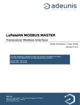
2. The power supply for the product
In order to wire these products, the lower part of the box must be opened by removing the two stainless steel
screws located on either side of this box.

30
208210A_UG_V1.6_ARFx3-PRO
Products from the ARFx3-PRO range must be powered by an external source which must be a minimum of 4.5V
and must not exceed 36 VDC. The green LED (located under the case) comes on when the power is on.
+ DC
Supply.
+ -
RX
TX
ON
RTS CTS
TX+ TX- RX+ RX-
ON
1 2
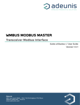
3. Wiring the serial link
3.1. DTE RS232 modem
ThisisthecaseforexamplewithamodemconnectedtoaPC.RTSandCTSarenotrequiredifyouuseow
control.
N° / SUB-D 9
NOM
+ Vcc
5
GND
2 RXD
3 TXD
+
-
RX
TX
RTS
CTS
TX+
TX-
RX+
RX-
ON
1 2
7
5
RTS
5
8
CTS
3.2. DCE RS232 modem
This is the case for example with a modem connected to a measuring device. RTS and CTS are not required if
youuseowcontrol.
N° / SUB-D 9
NOM
+ Vcc
5 GND
3 RXD
2
TXD
+
-
RX
TX
INHIB
RTS
CTS
TX+
TX-
RX+
RX-
ON
1 2
8 RTS
7 CTS
ActivityontheseriallinkcausesthegreenLEDtoash,whetherthedatatransmissionratechoseniscorrector
not.
GB

31
208210A_UG_V1.6_ARFx3-PRO
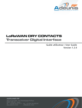
3.3. RS485 wiring
Wiring the RS485 bus only requires two cables:
• TX+ is connected to RX+.
• TX- is connected to RX- on the PCB.
BUS RS485
NAME
+ Vcc
GND
A TX+/RX+
B TX-/ RX-
+
-
RX
TX
INHIB
RTS
CT
S
TX+
TX-
RX+
RX-
Connect only TX-
or RX- (note 1)
Connect only
TX+ or RX+ (note
1)
Note 1:
TX- is connected to RX- on the PCB
TX+ is connected to RX+ on the PCB
ON
1 2
In order to enable RS485 management, the switch SW 1.1 must be ON and the S215 value must be 1 (cf table
below).
PLEASE NOTE
The switch SW1.1 is only read at power on. No change to the SW1.1 switch (while the modem is operating) will
be recognised.
S215 value SW1.1 Note
1 ON RS485 command line management
1 OFF RS232conguration
0 ignored RS232conguration
Table1:R485/232congurationsettings
By default, the DE and RE lines are declared LOW, thus permitting reception of characters from the RS485 dif-
ferential bus. The DE and RE lines are only declared HIGH when one or more characters need to be transmitted
by the RS485 differential bus: when a radio frame is demodulated, the lines are declared HIGH, then the data
extracted from the radio frame is sent to the TXD module, and as a consequence to the RS485 differential bus.
When the last character has been transmitted on the RS485 differential bus, the lines are declared LOW.
TXD
RE/DE
Tde
Data
Threshold 1µs
Figure 1: DE/RE timing when data is sent over the serial link
Threshold: minimum = 1 µs

32
208210A_UG_V1.6_ARFx3-PRO
Tde: set according to the value of the S219 register (see the table below).
S219 0 1 2 3 4 5 10 20 40 60 80
Tde
min
15 µs 35 µs 65 µs 135 µs 150 µs 190 µs 330 µs 600 µs 1.1 ms 1.7 ms 2.3 ms
In command mode, a response is sent (over the TXD line) according to the following DE/RE timing:
RXD
CMD
TXD
DE/RE
REPLY
≥700µs
≥100µs
≥100µs
The RS485 link needs to be adapted (on each side).
The modem includes a 100 W termination resistor:
• SW1.2=ON,theresistorisconnectedbetweenAandB(respectivelyRX+andRX-)
• SW1.2=OFF,theresistorisnotconnectedbetweenAandB.
If the modem is located at the end of the RS485 bus, SW1.1 must be set to ON.
100
Rt
SW1.2
B
A
B’ / Z
A’ / Y
R
T
B / RX-
A / RX+
Z / TX-
Y / TX+
R
T
MODEM
Network termination 485
RS485 Network
ActivityontheseriallinkcausesthegreenLEDtoash,whetherthedatatransmissionratechoseniscorrector
not.
GB

33
208210A_UG_V1.6_ARFx3-PRO
4. Radio communication
4.1. Radio communication
These modems offer several channels on the 863-870 MHz band that can be selected via the ADEUNIS RF
congurationsoftwareorusingATcommands.Thesechannelsaredistributedinwidebands(WB)andnarrow
bands (NB)
Wide band (WB) channels ARF53-PRO:
• 2widebandchannels
• 57.6kbit/stransmissionrate
• channelspacing:500kHz
• sensitivity:-108dBm
• selectivityonadjacentchannels:cf.§Selectivityonadjacentchannels
Narrow band (NB) channels ARF53-PRO:
• 67narrowbandchannels
• 10kbit/stransmissionrate
• channelspacing:100kHz
• sensitivity:-112dBm
• selectivityonadjacentchannels:cf.§Selectivityonadjacentchannels
Wide band (WB) channels ARF43-PRO:
• 2widebandchannels
• 57.6kbit/stransmissionrate
• channelspacing:500kHz
• sensitivity:-108dBm
• selectivityonadjacentchannels:cf.§Selectivityonadjacentchannels
Narrow band (NB) channels ARF43-PRO:
• 67narrowbandchannels
• 10kbit/stransmissionrate
• channelspacing:100kHz
• sensitivity:-112dBm
• selectivityonadjacentchannels:cf.§Selectivityonadjacentchannels
Wide band (WB) channels ARF33-PRO:
• 2widebandchannels
• 57.6kbit/stransmissionrate
• channelspacing:500kHz
• sensitivity:-108dBm
• selectivityonadjacentchannels:cf.§Selectivityonadjacentchannels
Narrow band (NB) channels ARF33-PRO:
• 67narrowbandchannels
• 10kbit/stransmissionrate
• channelspacing:100kHz
• sensitivity:-112dBm
• selectivityonadjacentchannels:cf.§Selectivityonadjacentchannels
This module is designed to operate according to CEPT/ERC/REC 70-03 recommendations. These recommen-
dations have been prepared by the European Radio-Communications Committee (ERC) which comes under
the European Conference of Postal and Telecommunications Administrations (CEPT). A requirement of this
recommendation depends on the client application. This is utilization of the product (duty cycle - CEPT / ERC /
REC 70-03). Each radio channel has its own limitation (0.1%, 1% or 10%). It is up to the user to comply with this
requirement according to the selected channel. For example: channels 1 and 84 are limited to a utilization rate of
10%. Then, the client application should therefore not use channel 1 or 84 more than 6 minutes in any one hour
period.

34
208210A_UG_V1.6_ARFx3-PRO
4.2. Radio channels
The S200 register allows you to choose the desired «channel/transmission rate/RF power» combination:
4.2.1 «Wide band» channels
«Wide band» channels are chosen according to the following table:
ARF53-PRO ARF43-PRO ARF33-PRO
Canal
S200
Frequency
(MHz)
Data rate
(kbps)
Power
(dBm)
Data rate
(kbps)
Power
(dBm)
Data rate
(kbps)
Power
(dBm)
1 869.525 57.6 27/24
(1)
57.6 17 57.6 10
3 868.25 57.6 14 57.6 14 57.6 10
4.2.2 «Narrow band» channels
The 67 «narrow band» channels are chosen according to the following table:
ARF53-PRO ARF43-PRO ARF33-PRO
Canal
S200
Frequency
(MHz)
Data rate
(kbps)
Power
(dBm)
Data rate
(kbps)
Power
(dBm)
Data rate
(kbps)
Power
(dBm)
18 869,55 10 20 10 17 10 10
19 869,45 10 20 10 14 10 10
22 869,15 10 14 10 14 10 10
23 869,05 10 14 10 14 10 10
24 868,95 10 14 10 14 10 10
25 868,85 10 14 10 14 10 10
26 868,75 10 14 10 14 10 10
28 868,55 10 14 10 14 10 10
29 868,45 10 14 10 14 10 10
30 868,35 10 14 10 14 10 10
31 868,25 10 14 10 14 10 10
32 868,15 10 14 10 14 10 10
33 868,05 10 14 10 14 10 10
34 867,95 10 14 10 14 10 10
35 867,85 10 14 10 14 10 10
36 867,75 10 14 10 14 10 10
37 867,65 10 14 10 14 10 10
38 867,55 10 14 10 14 10 10
39 867,45 10 14 10 14 10 10
40 867,35 10 14 10 14 10 10
41 867,25 10 14 10 14 10 10
42 867,15 10 14 10 14 10 10
43 867,05 10 14 10 14 10 10
44 866,95 10 14 10 14 10 10
45 866,85 10 14 10 14 10 10
GB

35
208210A_UG_V1.6_ARFx3-PRO
ARF53-PRO ARF43-PRO ARF33-PRO
Canal
S200
Frequency
(MHz)
Data rate
(kbps)
Power
(dBm)
Data rate
(kbps)
Power
(dBm)
Data rate
(kbps)
Power
(dBm)
46 866,75 10 14 10 14 10 10
47 866,65 10 14 10 14 10 10
48 866,55 10 14 10 14 10 10
49 866,45 10 14 10 14 10 10
50 866,35 10 14 10 14 10 10
51 866,25 10 14 10 14 10 10
52 866,15 10 14 10 14 10 10
53 866,05 10 14 10 14 10 10
54 865,95 10 14 10 14 10 10
55 865,85 10 14 10 14 10 10
56 865,75 10 14 10 14 10 10
57 865,65 10 14 10 14 10 10
58 865,55 10 14 10 14 10 10
59 865,45 10 14 10 14 10 10
60 865,35 10 14 10 14 10 10
61 865,25 10 14 10 14 10 10
62 865,15 10 14 10 14 10 10
63 865,05 10 14 10 14 10 10
64 864,95 10 14 10 14 10 10
65 864,85 10 14 10 14 10 10
66 864,75 10 14 10 14 10 10
67 864,65 10 14 10 14 10 10
68 864,55 10 14 10 14 10 10
69 864,45 10 14 10 14 10 10
70 864,35 10 14 10 14 10 10
71 864,25 10 14 10 14 10 10
72 864,15 10 14 10 14 10 10
73 864,05 10 14 10 14 10 10
74 863,95 10 14 10 14 10 10
75 863,85 10 14 10 14 10 10
76 863,75 10 14 10 14 10 10
77 863,65 10 14 10 14 10 10
78 863,55 10 14 10 14 10 10
79 863,45 10 14 10 14 10 10
80 863,35 10 14 10 14 10 10
81 863,25 10 14 10 14 10 10
82 863,15 10 14 10 14 10 10
83 863,05 10 14 10 14 10 10
84
(2)
869,525 10 27/24
(1)
10 17 10 10
85 869,6 10 17 10 17 10 10
Note 1: power is limited to 24dBm for USB versions.
Note 2: factory settings are shown in orange.

36
208210A_UG_V1.6_ARFx3-PRO
4.3. Selecting the radio transmission rate
The radio transmission rate is selected automatically when you set the channel number:
• Ifyouchoosechannelnumbers1or3,theradiotransmissionrateautomaticallyswitchesto57600bit/s.
• Ifyouchooseachannelnumber=18....85(cf¶4.2RadioChannels),themodulewilloperateinanar-
rowbandconguration.Theradiotransmissionrateautomaticallyswitchesto10kbit/s.
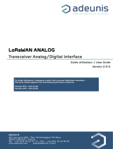
4.4. Adjacent channel selectivity
The graph below shows typical adjacent channel selectivity in wide band (WB) and narrow band (NB) modes.
NOTES
Particular attention is required when installing the product: in circumstances where several links are required to
operate within the same area (independently of channel positions), the minimum distance between two products
belonging to different radio links is 3 metres. Even with this precaution (depending on the product’s environ-
ment), adjacent channel selectivity may well be reduced.
4.5. RSSI reader
The RSSI indicator (Received Strength Signal Indicator) gives an indication of signal strength on the last frame
received. This can be accessed via the command ATS230?<cr>.
Power level
4.5.1 Adding RSSI for each frame via S300 = 2
S300=2 enables the serialization of the RSSI (<cr> ATS300 = 2). In transceiver mode, the RSSI is serialized
beforetherstcharacterreceivedbyRF.ThevalueofRSSIisexpressedindBm,withoutthe«-»sign,60to120
(-60 dBm to -120 dBm).
This mode can be used on RS232, USB and RS485 interfaces.
Warning: be careful to reset the value ATS300 to 0 (default) to stop the serialization of the RSSI.
NOTES
The RSSI is only an indication. Use it with care due to the dispersion between components. The diagram above
may change from one product to the next. The operating temperature may also have an impact on this disper-
sion.
The RSSI level can also indicate the possible presence of interference on the channel used.
TheRSSIisaconditionthatisnecessarytoobtaingoodreception,butisnotsufcient.
GB

37
208210A_UG_V1.6_ARFx3-PRO
5. The modem’s operating mode
Two operating modes are available:
• Commandmode(usingATcommands).
• Transmitter-receivermodeornormalmode(serialdataistransmittedviatheradiolink).
On power-up, the transmitter-receiver is in normal mode: it is able to send/receive data to/from a radio link accor-
dingtoitscurrentcongurationparameters.
5.1. Command mode
Commandmodeisusedtoreadandupdatethemodem’scongurationregistersusingATcommands.
NOTE
AT commands can be locked by using ATPWD commands.
In command mode, the radio is disabled (both for receiving and transmitting), except when the test command is
used.
Entry into command mode: broadcasts a +++ sequence on the serial link. The three consecutive + characters
are only accepted if there are no characters either before or after the + + + sequence. The register (S214)
denesthelengthofthesilence.
TIP 1
Ifyouareusingaterminal(suchasaHyperterm),youshouldsendthe+++sequencewithatextle(rst
createatextleonlycontainingthe+++characters,thenin«Hyperterm»,usethe«Sendtextle»command
from the «Transfer» menu).
TIP 2
Exiting command mode: (return to transmitter-receiver mode).
• send the serial command: ATO <cr>
When it receives a correct command, the modem responds:
• «O»<cr> (ASCII character 0x4F) in order to accept the command (command OK).
• «E»<cr> for an error.
• aspecicstringonrequest.
5.2. Transmitter-receiver mode
In transmitter-receiver mode, two protocols are available:
• Transparentmode,withoutowcontrol.
• Addressedmode,withowcontrol(cfS216register).

38
208210A_UG_V1.6_ARFx3-PRO
Communication is always half-duplex. The radio transmission is priority over the radio reception (when the tran-
ceiver sends a radio frame, it is not capable of decoding an incoming radio frame).
Modem turnaround time: minimum time to meet before responding to a query.
Distant Modem
(customer)
Local Modem
(server)
Serial line
RF Link
query
query
answer
Turnaround time ≥100µs
All the data received on the serial link is packed into a radio frame. The format of the radio frame depends on the
protocol used.
When the unit operates as a transmitter and receiver, the transmission of radio frame always begins with the
following conditions:
Detection of a silence on the serial link (more than S217) after the receipt of the latest character.
Or when the number of characters received from the serial link is higher or equal to the maximum size of the
radio frame (S218).
5.2.1 Transparent mode
In transparent mode, the modem acts like a cable link. This means that alternately, the modem sends data
received from the serial link on the radio link and sends data received from the radio link on the serial link.
The format of the radio frame is:
• <preamble><synchro> DATA <postamble>.
• preamble, synchronisation and postamble are used for radio reception.
5.2.2 Addressed mode
In transmission mode, data received from the serial link is sent on the radio link with the following format:
• <preamble><synchro><address> DATA <postamble>.
• preamble, synchronisation and postamble are used for radio reception.
• TheAddresseldisinitialisedwiththeS256value(LSBrst).
5.2.3 In reception mode
The<Address>eldintheradioframeischeckedwiththereceptionaddress(S252):
If the radio frame address corresponds to the transmitter-receiver reception address (S252), DATA (and only
DATA) is transmitted on the serial link.
Otherwise, the data received is ignored.
GB

39
208210A_UG_V1.6_ARFx3-PRO
5.3. Repeater mode
A repeater function is available in Addressed mode and in Transparent mode.
In Addressed mode, a product set in repeater mode also acts as a modem.
The use of a repeater in Transparent mode is different. The repeater product can not act as a modem.
• In this case, the products 1 and 2 are in Transparent mode
• ProductNo.3(repeater)mustbesetinAdressedmodeandconguredtorepeatall(registerS250=1)
• The minimum size of the package to be repeated must be 2 bytes.
5.4. The transmitter-receiver’s machine status
When the device is operating in transmitter-receiver mode, the «RF transmission» device’s status is:
• Transmitter-receiver idle: by default, the transmitter-receiver waits for incoming data on the RS232 link and a
radio frame on the radio link.
• The RS232 link takes priority over the radio link (if a radio frame is demodulated, certain RS232 characters
are detected on the serial link, the radio frame will be ignored and the incoming data on the RS232 link will
be processed).
• Processing of incoming data on the RS232: Incoming data on the RS232 link is placed in a memory buffer.
The data in the memory buffer is sent to a radio frame (RF modulation is initiated) when at least one of the
following conditions occur:
• Ifaninterruption(silencelongerthantheS217timeout)isdetectedontheincomingowfromtheseriallink
(no more data to be sent).
• If the size of the radio memory buffer is reached (the number of characters in the buffer is greater than or
equal to the S218 size).
• Processing of the incoming radio frame: Valid data is extracted from the incoming radio frame and placed in
the internal memory buffer. Data in the internal memory buffer is sent to the output via the RS232 protocol.

40
208210A_UG_V1.6_ARFx3-PRO
6. AT commands
6.1. Description
• AT commands are only interpreted when the transmitter-receiver is in command mode.
• The commands are used to read and update the modem’s parameters:
• A command starts with the 2 ASCII characters «AT» – «AT means «Attention» – followed by one or more
characters or other data.
• Each command terminates with a <cr> (carriage return).
• In the same command, the length of time between two characters must be less than 10 s.
NOTE
When it receives a correct command, the modem responds:
• «O»<cr> (ASCII character 0x4F) in order to accept the command (command OK).
• «E»<cr> for an error.
• aspecicstringonrequest.
6.2. The command set
Commands Description
Selecting operating mode
ATO Return to transmitter-receiver mode
<silence>+++<silence> Activating command mode The +++ sequence must
be preceded and followed by a calibrated silence (no
other characters)
Register management
ATSn? Displays the contents of the register Sn, where n
represent the number of the register.
The response will be in the following format:
Sn=y<cr><lf>
ATSn=m Assigns the value «m» to the register Sn; n represents
the number of the register.
AT&W SavesthenewregistercongurationintheEEPROM.
Each time you activate the modem, the EEPROM
congurationwillbeloadedintothemodem’sregis-
ters.
AT/S Displays all the register values. The response will
have the following format: Sxxx=y<cr><lf> for each
register.
AT/V Displays the software version. The response will
have the following format: Adeunis-RF_ARFx3-
PRO_868MHz_500mW Vxx.yy<cr><lf>
ATR Restores the default register values.
ATPWD=m m = pin code (register S205): unlocks all the AT com-
mands.
m = 0000: sets the register to the default value and
unlocks all the AT commands.
Test modes
ATT1 Pure carrier transmission (data=0) on the current
channel. This mode is exited by receiving any charac-
ter on the serial link.
GB

41
208210A_UG_V1.6_ARFx3-PRO
ATT2 Pure carrier transmission (data=1) on the current
channel. This mode is exited by receiving any charac-
ter on the serial link.
ATT3-ATT6
Modulation on the current channel. This mode is
exited by receiving any character on the serial link.
ATT3: 0.9 kHz modulation
ATT4: 3.6 kHz modulation
ATT5: 14.4 kHz modulation
ATT6: 28.8 kHz modulation
6.3. Description of the registers
Register values can be updated with the ATSn=m<cr> command and displayed with the ATSn?<cr> command.
Onpower-up,thetransmitter-receiver’spreviouscongurationisrestoredfromtheE2PROM(non-volatile)to
the RAM. The registers are located in the RAM registers, all changes are made in the RAM registers: in order to
savethecurrentregisterconguration,theAT&W<cr>commandmustbeused(otherwisetheupdatedparame-
ters will be lost if the power is cut).
The parameters are divided into 2 types: read only (R) or read/write (R/W).
Type Register Function Description Default value Note
Radio
manage-
ment
R/W S200 Channel
number
Radio channel for the 869 MHz version:
1 and 3: wide band channels
18 to 85: narrow band channels
84 3
R/W S202 Command
mode auto-
matic exit
Automatic exit from command mode 0: (no
specicmanagement),exitfromcommand
mode only when an ATO command is
issued.
From 1 to 60: timeout in seconds.
-> if no activity (no character, no command
received) is detected in command mode
during the programmed timeout, the system
will exit command mode. The module
returns to transmitter-receiver mode.
0
R/W S204 Preamble
length
Preamble length in ms from 4 to 50 20 4
R/W S217 Serial timeout
for radio
Serial timeout before the start of radio trans-
mission, in ms from 3 to 240
3 1
R/W S218 Radio frame
length
Size of the radio frame (from 1 to 240)
When the limit is reached:
• the transmitter-receiver sends a radio
frame
• the RTS signal is enabled only if the
module is operating in addressed mode
128
R S230 RSSI level Displays the reception level for the last mes-
sage received.
Response: S230=-xxx dBm<cr><lf> with xxx
decimal value.
Example S230=-80 dBm
None

42
208210A_UG_V1.6_ARFx3-PRO
R/W S231 RF exit level Adjusts the RF exit level
53-PRO 43-PRO 33-PRO
0 14dBm 10dBm 10dBm
1 20dBm 14dBm
2 24dBm 17dBm
3 27dBm
27/24dBm for the
ARF53-Pro
(note: USB versions are
set to 24dBm in order
to limit the current to
450mA)
17bBm for the
ARF43-PRO
IMPORTANT NOTES
«ERROR_1»: message returned when a user inserts an unauthorised value for the S200 register (in the light of
current regulations).
«WARNING_1»: message returned when a user inserts an authorised value for the S200 register, but the
content of the S231 register is not compatible with the maximum power permitted for the channel selected. As
a consequence, the S231 register is automatically updated with the maximum permitted value for the channel
selected.
«WARNING_2»: message returned when a user inserts a value that is available but not authorised for the S231
register (in the light of the maximum permitted power for the channel selected). As a consequence, the S231
register is automatically updated with the maximum permitted value for the channel selected.
Users must use the «AT&W» command if they wish to save the update.
«WARNING_3» : cf note 6
Type Register Function Description Default value Note
Serial link
R/W S210 Transmission rate Transmission rate of the serial link
in bits/s
«0»: 600
«1»: 1200
«2»: 2400
«3»: 4800
«4»: 9600
«5»: 19200
«6»: 38400
«7»: 57600
4 1.2 & 5
R/W S211 Data length «7»: 7 bits
«8»: 8 bits
8 5
R/W S212 Parity «1»: none
«2»: even
«3»: odd
1 5
R/W S213 Stop bits «1»: 1 stop bit
«2»: 2 stop bits
1 5
R/W S214 Timeout command Length of timeout for detecting ***,
in ms from 3 to 240
3 1
R/W S215 Type of interface «0»: RS232 only
«1»: RS232 or RS485 (DE/RE
lines managed)
1
R/W S216 Handshake «0» : hardware, RTS (limited to the
addressed protocol)
«2»: none
GB

43
208210A_UG_V1.6_ARFx3-PRO
R/W S219 RS485 delay Delay between DE activation and
therstRS485bytetransmitted
from 0 to 160
3
Protocol
R/W S220 Protocol «1» = transparent mode
«6»= addressed
6
R/W S252 Reception address from 0 to FFFF
Used in addressed protocol only, in
ordertoltertheincomingframe.
0xFFFF reserved for transmission
(additional information in “repeater
application note”)
R/W S256 Transmission
address
from 0 to FFFF
Used in addressed protocol only, in
ordertoltertheoutgoingframe.
Protocol
R/W S205 Pin Code Pin Code value
The value 0000 is not possible
1111
R/W S207 Pin Code activa-
tion
0 Pin code deactivated
1 Pin code activated
0
Function
repeater
R/W S244 Repeater number from 0 to 100
0: repetition is not enabled (default
value)
1-100 -> repeater enabled; this
valueisusedtodenethewaiting
period before transmission
(additional information in “repeater
application note»)
0
R/W S250 Forced repetition 0 -> Conditional repetition
1 -> Unconditional repetition
(additional information in “repeater
application note”)
0
R/W S300 RSSI serialization 0-> no serialized RSSI
2 -> serialized RSSI
0 6
NOTE 1
When a change of serial speed is requested, the values of the S214 and S217 registers are automatically set to
a value greater than or equal to the period of three characters at the speed requested (13 ms for 2400 bauds, 7
ms for 4800, otherwise 3 ms)
NOTE 2
Transmissionmodewithoutowcontrol.Pleasenotethatusingaserialtransmissionratethatishigherthanthe
radiotransmissionratewillofnecessityleadtothelossofcharactersintheabsenceofowcontrol.
If the radio transmission rate is equal to the serial transmission rate, the radio frame is longer than the serial
frame due to the header required by the radio protocol; but the radio header will only be generated at the start of
the radio transmission and this header will be absorbed by the size of the internal buffer.
For example, if the current radio transmission rate is 10 kbits/s, a serial transmission rate of 9600 must be used
withoutowcontrol,whileaserialtransmissionrateof19,200(with10kbits/sfortheradiotransmissionrate)will
produceadataoverow.

44
208210A_UG_V1.6_ARFx3-PRO
In order to prevent loss of characters, you should:
• useowcontrol(addressedmodewithhardwarehandshake).
• or use a serial transmission rate less than or equal to the radio transmission rate.
• or limit the size of the serial data to the maximum size of the internal buffer (S218).
NOTE 3
(S200 register) cf page 10.
NOTE 4
The preamble length is linked to the current radio transmission rate.
Preamble values are:
The default preamble length The minimum preamble length
wide band channel
(high radio transmission rate)
5 ms 4 ms
narrow band channel
(low radio transmission rate)
20 ms 10 ms
PLEASE NOTE
It should be borne in mind that reducing the default preamble length will reduce the transmission delay but risks
generating possible errors in the frame transmission rate (up to 1 or 2/1000)!
In the case of narrow band, it is not possible to set the preamble length below 10ms.
NOTE 5
Whenyouchangetheseriallinkconguration(transmissionrate,parity,stopbit…),theresponseismadewith
the previous format of the serial link. It is the next command that will be sent using the new format of the serial
link.
NOTE 6
When the serialization of the RSSI is selected (at receiver), a warning (WARNING_3) appears, asking the user to
ensurethatthesideofthetransmitter,theowattheselectedserialisequaltotheselectedradio.
In the opposite case, a phenomenon of fragmentation of data may appear, making it completely unusable data
received on the serial link.
7. Specications
7.1. General technical characteristics
Operating temperature -30 to +70 °C
Electricity power supply 4.5 to 36 V (integrated regulator)
Dimensions 145 x 100 x 40 mm
Number of channels 2 WB channels and 67 NB channels
Modulation GFSK
Case IP65 case with integrated or external aerial
Transmitter
Frequencies programmable from 863.05 to 869.60MHz
RF transmitted power programmable from 10 to 27dBm
Tx / Rx consumption 3.2 W / 0.27 W
Receiver
GB
Page is loading ...
Page is loading ...
Page is loading ...
Page is loading ...
Page is loading ...
Page is loading ...
Page is loading ...
Page is loading ...
Page is loading ...
Page is loading ...
Page is loading ...
Page is loading ...
Page is loading ...
Page is loading ...
Page is loading ...
Page is loading ...
Page is loading ...
Page is loading ...
Page is loading ...
Page is loading ...
Page is loading ...
Page is loading ...
Page is loading ...
Page is loading ...
Page is loading ...
Page is loading ...
Page is loading ...
Page is loading ...
Page is loading ...
Page is loading ...
Page is loading ...
Page is loading ...
Page is loading ...
Page is loading ...
Page is loading ...
Page is loading ...
Page is loading ...
Page is loading ...
Page is loading ...
Page is loading ...
Page is loading ...
Page is loading ...
Page is loading ...
Page is loading ...
Page is loading ...
Page is loading ...
Page is loading ...
Page is loading ...
Page is loading ...
Page is loading ...
Page is loading ...
Page is loading ...
Page is loading ...
Page is loading ...
Page is loading ...
Page is loading ...
Page is loading ...
Page is loading ...
Page is loading ...
Page is loading ...
Page is loading ...
Page is loading ...
Page is loading ...
Page is loading ...
-
 1
1
-
 2
2
-
 3
3
-
 4
4
-
 5
5
-
 6
6
-
 7
7
-
 8
8
-
 9
9
-
 10
10
-
 11
11
-
 12
12
-
 13
13
-
 14
14
-
 15
15
-
 16
16
-
 17
17
-
 18
18
-
 19
19
-
 20
20
-
 21
21
-
 22
22
-
 23
23
-
 24
24
-
 25
25
-
 26
26
-
 27
27
-
 28
28
-
 29
29
-
 30
30
-
 31
31
-
 32
32
-
 33
33
-
 34
34
-
 35
35
-
 36
36
-
 37
37
-
 38
38
-
 39
39
-
 40
40
-
 41
41
-
 42
42
-
 43
43
-
 44
44
-
 45
45
-
 46
46
-
 47
47
-
 48
48
-
 49
49
-
 50
50
-
 51
51
-
 52
52
-
 53
53
-
 54
54
-
 55
55
-
 56
56
-
 57
57
-
 58
58
-
 59
59
-
 60
60
-
 61
61
-
 62
62
-
 63
63
-
 64
64
-
 65
65
-
 66
66
-
 67
67
-
 68
68
-
 69
69
-
 70
70
-
 71
71
-
 72
72
-
 73
73
-
 74
74
-
 75
75
-
 76
76
-
 77
77
-
 78
78
-
 79
79
-
 80
80
-
 81
81
-
 82
82
-
 83
83
-
 84
84
-
 85
85
-
 86
86
-
 87
87
-
 88
88
-
 89
89
-
 90
90
-
 91
91
-
 92
92
-
 93
93
-
 94
94
-
 95
95
-
 96
96
-
 97
97
-
 98
98
-
 99
99
-
 100
100
-
 101
101
-
 102
102
-
 103
103
-
 104
104
-
 105
105
-
 106
106
-
 107
107
-
 108
108
-
 109
109


Ask a question and I''ll find the answer in the document
Finding information in a document is now easier with AI
in other languages
- italiano: ADEUNIS ARFx3 PRO Guida utente
- français: ADEUNIS ARFx3 PRO Mode d'emploi
- español: ADEUNIS ARFx3 PRO Guía del usuario
- Deutsch: ADEUNIS ARFx3 PRO Benutzerhandbuch
Related papers
-
 ADEUNIS ARF868 LP/LR/MR/ULR User guide
-
 ADEUNIS ARF 868 LP User guide
-
ADEUNIS FTD / V1.1.2 et V1.1.1 User guide
-
 ADEUNIS MODBUS V1.0.1 User guide
-
 ADEUNIS WMBUS Repeater User manual
-
 ADEUNIS FIELD TEST DEVICE LoRaWAN- Sigfox / V1.2.2 et V1.1.3 User guide
-
 ADEUNIS MODBUS V1.0.1 User guide
-
 ADEUNIS DRY CONTACTS / V1.2.0 User guide
-
 ADEUNIS ANALOG V1.2.0 User guide
-
 ADEUNIS ANALOG PWR / V1.2.0 User guide


Other documents
-
 Adeunis RF ARF54 User manual
-
Abocom AFM-100 User manual
-
Warwick X7220 User manual
-
 Adeunis RF ARF18 User manual
-
Adeunis RF ARF8055AA User manual
-
Renkforce 4 ports Serial hub Owner's manual
-
Alcatel XP Getting Started Manual
-
-
Phoenix PSM-ME-RS232/RS485-P Installation Notes For Electricians
-

