Johnson Controls M Series Owner's manual
- Category
- Split-system air conditioners
- Type
- Owner's manual
This manual is also suitable for

Owner's Manual
Air Conditioning Unit
"M" and "W" Series
24K Multi Zone System
Cassette Type Indoor Unit
Model:
DHMW24NKB21S
Please read this Installation and Operation manual
carefully before installation and operation and retain it for
future reference.

2
P5415467
Important Notice
● Johnson Controls, Inc. pursues a policy of continuing improvement in design and performance in its
products. As such, Johnson Controls, Inc. reserves the right to make changes at any time without
prior notice.
● Johnson Controls, Inc. cannot anticipate every possible circumstance that might involve a potential hazard.
● This inverter air conditioning unit is designed for standard air conditioning applications only. Do not use
this unit for anything other than the purposes for which it was intended for.
● The installer and system specialist shall safeguard against leakage in accordance with local pipetter
and electrical codes. The following standards may be applicable, if local regulations are not available.
International Organization for Standardization: (ISO 5149 or European Standard, EN 378). No part of
this manual may be reproduced in any way without the expressed written consent of Johnson Controls,
Inc.
● This inverter-driven (cooling or heat pump) air conditioning unit will be operated and serviced in the
United States of America and comes with all required Safety, Danger, and Caution, warnings.
● If you have questions, please contact your distributor or dealer.
● This manual provides common descriptions, basic and advanced information to maintain and service
this inverter-driven (cooling or heat pump) air conditioning unit which you operate, as well for other
models.
● This inverter-driven (cooling or heat pump) air conditioning unit has been designed for a specic
temperature range. For optimum performance and long life, operate this unit within range limits.
● This manual should be considered as a permanent part of the air conditioning equipment and should
remain with the air conditioning equipment.
Product Inspection upon Arrival
1. Upon receiving this product, inspect it for any damages incurred in transit. Claims for damage, either
apparent or concealed, should be led immediately with the shipping company.
2. Check the model number, electrical characteristics (power supply, voltage, and frequency rating), and
any accessories to determine if they agree with the purchase order.
3. The standard utilization for this unit is explained in these instructions. Use of this equipment for
purposes other than what it designed for is not recommended.
4. Please contact your local agent or contractor as any issues involving installation, performance, or
maintenance arise. Liability does not cover defects originating from unauthorized modications
performed by a customer without the written consent of Johnson Controls, Inc. Performing any
mechanical alterations on this product without the consent of the manufacturer will render your
warranty null and void.

1 Additional Usage Information...........................................................................1
2 Installation of Cassette Type Indoor Unit .........................................................2
2.1 Schematic Diagram of Installation Spaces ............................................................ 2
2.2 Installation Location of the Indoor Unit ................................................................... 2
2.3 Important Notice. ....................................................
................................................ 3
2.4 Dimensions of Ceiling Opening and Location of Threaded Mounting Rod ............ 3
2.5 Installation of Cassette Chassis ...........................................................................
4
2.6 Refrigerant Piping Connections........
....................................................................... 4
2.7 Condensate Hose...................................................................................................
5
2.8 Electrical wiring ...................................................................................................... 7
2.9 Grille Installation ...................................................
.................................................. 9
3 Nomenclature of Cassette Type Indoor Unit ................................................12
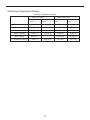
4 Working Temperature Range .........................................................................13
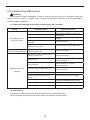
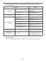
5 Troubleshooting Malfunctions.
........................................................................14
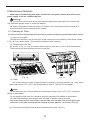
6 Maintenance Methods .
.................................................................................... 16
16
6.1 Cleaning Air Filter................................................................................................
6.2 Cleaning Air Inlet Grille .....................................
6.3 Installing and Changing Air Purifier ...............................................
6.4 Cleaning of Surfaces and Louvers.....................
6.5 Seasonal Maintenance...................................................................................
......
18
Table of Contents
Introduction and Safety Information.....................................................................i
Support Contact Information.............................................................................19
...................................................17
......................17
..................................................18

31
P5415467
1. Introduction
This manual should be considered as a permanent part of the air conditioning equipment and should
remain with the air conditioning equipment.
This manual concentrates on inverter-driven cooling or heat pump air conditioning units. Read this manual
carefully before installation.
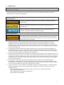
2. Important Safety Instructions
Safety Messages
Indicates a hazardous situation that, if not avoided, could result in death or
serious injury.
Indicates a hazardous situation that, if not avoided, could result in minor or
moderate injury.
Indicates information considered important, but not hazard-related (for
example, messages relating to property damage).
General Precautions
To reduce the risk of serious injury or death, read these instructions
thoroughly and follow all warnings or cautions included in all manuals that
accompanied the product and are attached to the unit. Refer back to these
safety instructions as needed.
● This system should be installed by personnel certied by Johnson Controls, Inc. Personnel must be
qualied according to local, state and national building and safety codes and regulations. Incorrect
installation could cause leaks, electric shock, re or explosion. In areas where Seismic ‘’Performance
requirements are specied, the appropriate measures should be taken during installation to guard against
possible damage or injury that might occur in an earthquake if the unit is not installed correctly, injuries may
occur due to a falling unit.
● Use appropriate Personal Protective Equipment (PPE), such as gloves and protective goggles and,
where appropriate, have a gas mask nearby. Also use electrical protection equipment and tools suited
for electrical operation purposes. Keep a quenching cloth and a re extinguisher nearby during brazing.
Use care in handling, rigging, and setting of bulky equipment.
● When transporting, be careful when picking up, moving and mounting these units. Although the unit may
be packed using plastic straps, do not use them for transporting the unit from one location to another. Do
not stand on or put any material on the unit. Get a partner to help, and bend with your knees when lifting
to reduce strain on your back. Sharp edges or thin aluminum ns on the air conditioner can cut ngers,
so wear protective gloves.
● Do not touch or adjust any safety devices inside the indoor or outdoor units. All safety features,
disengagement, and interlocks must be in place and functioning correctly before the equipment is put
into operation. If these devices are improperly adjusted or tampered with in any way, a serious accident
can occur. Never bypass or jump-out any safety device or switch.
● Johnson Controls, Inc. will not assume any liability for injuries or damage caused by not following steps
outlined or described in this manual. Unauthorized modications to Johnson Controls products are
prohibited as they…
◦ May create hazards which could result in death, serious injury or equipment damage.
◦ Will void product warranties.
◦ May invalidate product regulatory certications.
◦ May violate OSHA standards.
i

4
P5415467
Take the following precautions to reduce the risk of property damage.
● Be careful that moisture, dust, or variant refrigerant compounds not enter the refrigerant cycle during
installation work. Foreign matter could damage internal components or cause blockages.
● If air lters are required on this unit, do not operate the unit without the air lter set in place. If the air
lter is not installed, dust may accumulate and breakdown may result.
● Do not install this unit in any place where silicon gases can coalesce. If the silicon gas molecules
attach themselves to the surface of the heat exchanger, the nned surfaces will repel water. As a
result, any amount of condensate can overow from the condensate pan and could run inside of the
electrical box, possibly causing electrical failures.
● When installing the unit in a hospital or other facility where electromagnetic waves are generated
from nearby medical and/or electronic devices, be prepared for noise and electronic interference
Electromagnetic Interference (EMI). Do not install where the waves can directly radiate into the
electrical box, controller cable, or controller. Inverters, appliances, high-frequency medical equipment,
and radio communications equipment may cause the unit to malfunction. The operation of the unit
may also adversely affect these same devices. Install the unit at least 10 ft. (approximately 3m) away
from such devices.
● When a wireless zone controller is used, locate at a distance of at least 3.3 ft. (approximately 1 meter)
between the indoor unit and electric lighting. If not, the receiver part of the unit may have difculty
receiving operation commands.
● Do not install the unit in any location where animals and plants can come into direct contact with the
outlet air stream. Exposure could adversely affect the animals and plants.
● Do not install the unit with any downward slope to the side of the drain boss. If you do, you may have
water owing back which may cause leaks.
● Be sure the condensate hose discharges water properly. If connected incorrectly, it may cause leaks.
● Do not install the unit in any place where oil can seep onto the units, such as table or seating areas in
restaurants, and so forth. For these locations or social venues, use specialized units with oil-resistant
features built into them. In addition, use a specialized ceiling fan designed for restaurant use. These
specialized oil-resistant units can be ordered for such applications. However, in places where large
quantities of oil can splash onto the unit, such as a factory, even the specialized units cannot be used.
These products should not be installed in such locations.
Installation Precautions
To reduce the risk of serious injury or death, the following installation
precautions must be followed.
● When installing the unit into…
▫ A wall: Make sure the wall is strong enough to hold the unit’s weight. It may be necessary to
construct a strong wood or metal frame to provide added support.
▫ A room: Properly insulate any refrigerant tubing run inside a room to prevent “sweating” that can
cause dripping and water damage to wall and oors.
▫ Damp or uneven areas: Use a raised concrete pad or concrete blocks to provide a solid, level
foundation for the unit to prevent water damage and abnormal vibration.
▫ An area with high winds: Securely anchor the outdoor unit down with bolts and a metal frame.
Provide a suitable air bafe.
▫ A snowy area (only for heat pump model): Install the outdoor unit on a raised platform that is
higher than drifting snow. Provide snow vents.
● Do not install the unit in the following places. Doing so can result in an explosion, re, deformation,
corrosion, or product failure.
▫ Explosive or ammable atmosphere
▫ Where re, oil, steam, or powder can directly enter the unit, such as in close proximity or directly
above a kitchen stove.
▫ Where oil (including machinery oil) may be present.
▫ Where corrosive gases such as chlorine, bromine, or sulde can accumulate, such as near a hot
tub or hot spring.
▫ Where dense, salt-laden airow is heavy, such as in coastal regions.
▫ Where the air quality is of high acidity.
▫ Where harmful gases can be generated from decomposition.
ii

5
P5415467
● Do not position the condensate pipe for the indoor unit near any sanitary sewers where corrosive
gases may be present. If you do, toxic gases can seep into breathable air spaces and can cause
respiratory injuries. If the condensate pipe is installed incorrectly, water leakage and damage to the
ceiling, oor, furniture, or other possessions may result. If condensate piping becomes clogged,
moisture can back up and can drip from the indoor unit. Do not install the indoor unit where such
dripping can cause moisture damage or uneven locations: Use a raised concrete pad or concrete
blocks to provide a solid, level foundation for the unit to prevent water damage and abnormal
vibration.
● Before performing any brazing work, be sure that there are no ammable materials or open
ames nearby.
● Perform a run test to ensure normal operation. Safety guards, shields, barriers, covers, and protective
devices must be in place while the compressor/unit is operating. During the test run, keep ngers and
clothing away from any moving parts.
● Clean up the site when nished, remembering to check that no metal scraps or bits of wiring have
been left inside the unit being installed.
● During transportation, do not allow the backrest of the forklift to make contact with the unit,
otherwise, it may cause damage to the heat exchanger and also may cause injury when
stopped or started suddenly.
● Remove gas inside the closing pipe when the brazing work is performed. If the brazing ller metal is
melted with remaining gas inside, the pipes will be blown off and it may cause injury.
● Be sure to use nitrogen gas for an airtight test. If other gases such as oxygen gas, acetylene gas or
uorocarbon gas are accidentally used, it may cause explosion or gas intoxication.
After installation work for the system has been completed, explain the “Safety Precautions,” the proper use
and maintenance of the unit to the customer according to the information in all manuals that came with the
system. All manuals and warranty information must be given to the user or left near the Indoor Unit.
Refrigerant Precautions
To reduce the risk of serious injury or death, the following refrigerant
precautions must be followed.
● As originally manufactured, this unit contains refrigerant installed by Johnson Controls. Johnson
Controls uses only refrigerants that have been approved for use in the unit’s intended home country
or market. Johnson Controls distributors similarly are only authorized to provide refrigerants that
have been approved for use in the countries or markets they serve. The refrigerant used in this unit
is identied on the unit’s faceplate and/or in the associated manuals. Any additions of refrigerant into
this unit must comply with the country’s requirements with regard to refrigerant use and should be
obtained from Johnson Controls distributors. Use of any non-approved refrigerant substitutes will void
the warranty and will increase the potential risk of injury or death.
● If installed in a small room, take measures to prevent the refrigerant from exceeding the maximum
allowable concentration in the event that refrigerant gases should escape. Refrigerant gases can
cause asphyxiation (0.42 kg/m3 based on ISO 5149 for R410A). Consult with your distributor for
countermeasures (ventilation system and so on). If refrigerant gas has leaked during the installation
work, ventilate the room immediately.
● The design pressure for this product is 601 psi (4.15MPa). The pressure of R410A refrigerant is 1.4
times higher than that of the refrigerant R22. Therefore, the refrigerant piping for R410A shall be
thicker than that for R22. Make sure to use the specified refrigerant piping. If not, the refrigerant
piping may r
upture due to an excessive refrigerant pressure. Besides, pay attention to the piping
thickness when using copper refrigerant piping. The thickness of copper refrigerant piping differs
depending on its material.
● The refrigerant R410A is adopted. The refrigerant oil tends to be affected by foreign matters such
as moisture, oxide lm, (or fat). Perform the installation work with care to prevent moisture, dust, or
different refrigerant from entering the refrigerant cycle. Foreign matter can be introduced into the
cycle from such parts as expansion valve and the operation may be unavailable.
● To avoid the possibility of different refrigerant or refrigerant oil being introduced into the cycle, the
sizes of the charging connections have been changed from R407C type and R22 type. It is necessary
to prepare the appropriate tools before performing the installation work.
● Use refrigerant pipes and joints which are approved for use with R410A.
● A compressor/unit comprises a pressurized system. Never loosen threaded joints while the system is
iii

6
P5415467
under pressure and never open pressurized system parts.
● Before installation is complete, make sure that the refrigerant leak test has been performed. If
refrigerant gases escape into the air, turn OFF the main switch, extinguish any open ames and
contact your service contractor. Refrigerant (Fluorocarbon) for this unit is odorless. If the refrigerant
should leak and come into contact with open ames, toxic gas could be generated. Also, because the
uorocarbons are heavier than air, they settle to the oor, which could cause asphyxiation.
● When installing the unit, and connecting refrigerant piping, keep all piping runs as short as
possible, and make sure to securely connect the refrigerant piping before the compressor starts
operating. If the refrigerant piping is not connected and the compressor activates with the stop
valve opened, the refrigerant cycle will become subjected to extremely high pressure, which can
cause an explosion or re.
● Tighten the are nut with a torque wrench in the specied manner. Do not apply excessive force to the
are nut when tightening. If you do, the are nut can crack and refrigerant leakage may occur.
● When maintaining, relocating, and disposing of the unit, dismantle the refrigerant piping after the
compressor stops.
● When pipes are removed out from under the piping cover, after the insulation work is completed,
cover the gap between the piping cover and pipes by a packing (eld-supplied). If the gap is not
covered, the unit may be damaged if snow, rain water or small animals enter the unit.
● Do not apply an excessive force to the spindle valve at the end of opening. Otherwise, the spindle
valve ies out due to refrigerant pressure. At the run test, fully open the gas and liquid valves,
otherwise, these devices will be damaged. (It is closed before shipment.)
● If the arrangement for outdoor units is incorrect, it may cause owback of the refrigerant and result in
failure of the outdoor unit.
● The refrigerant system may be damaged if the slope of the piping connection kit exceeds +15
o
.
Electrical Precautions
Take the following precautions to reduce the risk of electric shock, re or
explosion resulting in serious injury or death.
● Highly dangerous electrical voltages are used in this system. Carefully refer to the wiring diagram
and these instructions when wiring. Improper connections and inadequate grounding can cause
serious injury or death.
● Perform all electrical work in strict accordance with this installation and maintenance manual and all
the relevant regulatory standards.
● Before servicing, open and tag all disconnect switches. Never assume electrical power is
disconnected. Check with meter and equipment.
● Only use electrical protection equipment and tools suited for this installation.
● Use specied cables between units.
● The new air conditioner may not function normally in the following instances:
▫ If electrical power for the new air conditioner is supplied from the same transformer as the device*
referred to below.
▫ If the power source cables for this device* and the new air conditioner unit are located in close
proximity to each other.
Device*: (Example): A lift, container crane, rectier for electric railway, inverter power
device, arc furnace, electric furnace, large-sized induction motor and large-sized switch.
Regarding the cases mentioned above, surge voltage may be inducted into the power supply
cables for the packaged air conditioner due to a rapid change in power consumption of the
device and an activation of a switch.
Check eld regulations and standards before performing electrical work in order to protect the
power supply for the new air conditioner unit.
iv

7
P5415467
● Communication cabling shall be a minimum of 18-Gauge, 2-Conductor, Stranded Copper. Shielded
cable must be considered for applications and routing in areas of high EMI and other sources of
potentially excessive electrical noise to reduce the potential for communication errors. When shielded
cabling is applied, proper bonding and termination of the cable shield is required as per Johnson
Controls guidelines. Plenum and riser ratings for communication cables must be considered per
application and local code requirments.
● Use an exclusive power supply for the air conditioner at the unit’s rated voltage.
● Be sure to install circuit breakers (ground fault interrupter, isolating switch, molded case circuit
breaker and so on), with the specied capacity. Ensure that the wiring terminals are tightened securely
to recommended torque specications.
● Clamp electrical wires securely with a cable clamp after all wiring is connected to the terminal block.
In addition, run wires securely through the wiring access channel.
● When installing the power lines, do not apply tension to the cables. Secure the suspended cables at
regular intervals, but not too tightly.
● Make sure that the terminals do not come into contact with the surface of the electrical box. If the
terminals are too close to the surface, it may lead to failures at the terminal connection.
● Turn OFF and disconnect the unit from the power source when handling the service connector. Do not
open the service cover or access panel to the indoor or outdoor units without turning OFF the main
power supply.
● After ceasing operation, be sure to wait at least ve minutes before turning off the main power
switch. Otherwise, water leakage or electrical breakdown may result. Disconnect the power source
completely before attempting any maintenance for electrical parts. Check to ensure that no residual
voltage is present after disconnecting the power source.
● Do not clean with, or pour water into, the controller as it could cause electric shock and/or damage the
unit. Do not use strong detergent such as a solvent. Clean with a soft cloth.
● Check that the ground wire is securely connected. Do not connect ground wiring to gas piping, water
piping, lighting conductor, or telephone ground wiring.
● If a circuit breaker or fuse is frequently activated, shut down the system and contact your
service contractor.
● Perform all electrical work in accordance with this manual and in compliance with all regulations and
safety standards.
● Do not open a service access cover or panel of an indoor or outdoor unit without rst turning OFF the
power at the main power supply.
● Residual voltage can cause electric shock. At all times, check for residual voltage after disconnecting
from the power source before starting work on the unit.
● This equipment can be installed with a Ground Fault Circuit Breaker (GFCI), which is a recognized
measure for added protection to a properly grounded unit. Install appropriate sized breakers/fuses/
overcurrent protection switches, and wiring in accordance with local, state and NEC codes and
requirements. The equipment installer is responsible for understanding and abiding by applicable
codes and requirements.
v

Additional Usage Information
◆ When purchasing or installing multi-zone DFS systems, the combination ratio must not
exceed 150% of outdoor unit capacity. If the connecting indoor units exceed the recommended
combination ratio then capacity will be greatly reduced and may damage the system.
◆ When
all indoor units are not set to the same operating mode, the malfunction light will blink
after 5 seconds on the indoor unit or remote controller showing mode conflict. The indoor units that
are set to the same mode will operate normally but the different mode unit will display a different
mode error and will not operate until mode is changed. The cooling mode will not conflict with the
dry mode, and the fan mode will not conflict with any mode.
◆ The outdoor unit disconnect should be installed within reach of the outdoor unit and at such
a height for easy access. Overcurrent protection is required (UL 1995,CSAC22.2).
◆ The cooling range of the unit is the outdoor environment temp.-5~48°C DB, the heating
range of the unit (only for the heat pump type unit) is the outdoor environment temperature
-15~27°C WB.
This product must not be disposed of along with domestic waste. This product has to be
disposed of at an authorized place for recycling of electrical and electronic appliances.
1

2
2 Installation of Cassette Indoor Unit
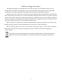
2.1 Schematic Diagram of Installation Spaces
Model
DHMW24NKB21S
H
260
unit:mm
>20
Wall
surface
Wall
surface
Wall
surface
Ground
surface
H
Fig.1
2.2 Installation Location of the Indoor Unit
(1). There should be no obstructions near the intake or outlet of the indoor unit as this may
restrict airflow.
(2). Make sure that the installation is in accordance with the requirements of the
schematic diagram of installation spaces.
(3). Select a location that can withstand four times the weight of the indoor unit while
taking into account operating noise and vibration.
(4). Ensure unit is level.
(5). Select a location for the indoor unit taking into account routing of the condensate line and
proximity to the outdoor unit.
(6). Make sure that there is enough space for care and maintenance. Make sure that the
weight between the indoor unit and ground is above 6 ft. (1800mm).
(7). When installing the threaded mounting rod, check if the installation location can
withstand a weight four times that of the unit’s. If not, reinforce before installation. (Refer to
the installation cardboard to find where reinforcements should be made.)
8). Ensure that the exhaust ventilator hood above a stove has enough capacity to remove
cooking smoke and oils as this will impact the operation of the unit over time.
(9). Installation of the indoor unit in a kitchen is not recommended as this may impact overall
performance due to environmental factors.

3
2.3 Important Notice:
◆ To ensure good performance and longevity, the unit must be installed by certified
technicians according to these instructions.
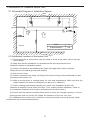
2.4 Dimensions of Ceiling Opening and Location of Threaded Mounting Rod
Refrigerant pipe
33" ( Indoor unit)
30-3/4" (Gaps between hoisting screw
rods)
35" *(Ceiling opening)
37-1/2" (Decorated surface boards)
Threaded mounting
rod (X4)
33" ( Indoor unit)
35" (Ceiling opening)
37-1/2" (Decorated surface
boards)
26-3/4" (Gaps between hoisting screw rods)
Fig. 2 Installation Dimensions of Model DHMW24NKB21S
◆ The drilling of holes in the ceiling must be done by certified technicians.
Ceiling
Installation stands for main body of the unit
(6-1/4")
Above 25/32"
Fig. 3
Note: The dimensions for the ceiling openings with * marks can be as large as 3 ft.
(910mm). The cassette grille assembly should overlap the finished ceiling by at least 13/16 in.
(20mm).

4
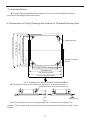
(1). The primary steps for installing the indoor unit.
◆ When attaching the mounting bracket onto the threaded rod, use the appropriate bolts and
washers capable of supporting the weight of the chassis. The use of field supplied mounting cleats
to supplement the chassis mounting brackets will provide additional support and prevent possible
damage or breakage of the washers.
(2). Use the cardboard template.
◆
Please refer to the installation cardboard templatefor the dimensions of the ceiling opening.
◆ The central mark of the ceiling opening is marked on the installation cardboard.
◆ Install the cardboard template on the unit with bolts (three), and check the angle of the
condensate outlet.
(3). Mount the unit to the previously installed threaded mounting rod. (Refer to Fig. 2 above.)
(4). The unit must be level to operate correctly and to prevent water damage to ceiling and
surroundings.
◆ Condensate pump and float switch are included in the indoor unit.
(5). Slide out the gasket anchor board used to prevent the gasket from breaking off and tighten
the nut on it.
(6). Remove the template.
Nut (field-supplied)
Washer(accessory)
Washer anchor board(attachment)
Bolt of one of the angles of outlet pipe is
secured on the angle of the drainage slot
Bolt(accessory)
Water level
Polyethylene pipe
Center of the ceiling
opening
Insert
Install cardboard
Mounting bracket
Tighten(locking nuts)
Securely tighten all hardware ]
Secure the washer firmly]
Bolt (accessory)
Secure the install ation cardboard]
Fig. 4
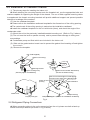
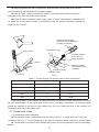
2.6 Refrigerant Piping Connections
◆ When connecting piping to the unit or removing from the unit, please use both a back-up
wrench and torque wrench (as shown in Fig.5 below).
2.5 Installation of Cassette Chassis

5
◆ When completing the flare connections, start the flare nuts by hand; then use the
two wrenches as described above to properly tighten.
◆ Refer to Table 1 below if the torque setting is too high then the flare nut may be
damaged or the flare may crack causing leaks.
◆ Check all flare connections with soapy water or other leak detection method and if
no leaks are found, then insulate all connections with the proper insulating material as
shown in Fig. 5 below.
Wrench
Thread fastener (X4)
Ensure that the insulating
material is securely fastened to
the piping connections
Suction ling tubing
Liquid line tubing
Insulating material
must cover the
piping completely
Insulating material
must cover the piping
completely
Flare nut
Torque wrench
Fig. 5
Table 1: Torque settings for various sizes of flare connections
Diameter
(
Inch
)
Surface thickness
(
mm
)
Moment of torque (N
·
m)
φ1/4’’
≥
0.5 10-15
φ3/8’’
≥
0.71 25-32
φ1/2’’
≥
1 36-48
φ5/8’’
≥
1 51-62
φ3/4’’
≥
1 70-86
If the specification of the outdoor unit pipe joint does not conform to that of the indoor unit, then
the joint specification of the outlet pipe of the indoor unit takes precedence. A reducing nipple
should be installed at the joint of the outdoor unit so as to make the joint of the outdoor unit
compatible with that of the indoor unit.
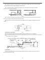
2.7 Condensate Hose
(1). Condensate hose installation
◆ The diameter of the condensate hose should be equal to, or larger than, the unit's pipe
connection which is 1". (This will depend on the type of connection being used to join the two pipes.)
◆ Condensate hose should be installed with gravity fall and supported to prevent drainage
issues.

6
◆ If gravity fall cannot be achieved due to obstructions or install limits, then a riser will need
◆ To prevent bending or warping of the drain line, the supporting brackets should be
installed in 3'-5' spans as needed.
1-1.5m
Proper install with correct fall
Fig. 6
◆ If unit has a connection kit included, use this to connect field drain to the indoor unit outlet.
Do not over tighten clamps as drain outlet may crack.
◆ The drain line must be insulated with no air gaps and then properly clamped as described
Fig.
7
Drain Step
-
up Pipe Note
◆ The installation height of the drain-raising pipe should less than 11 in. (280mm).
◆ The condensate pipe riser should form a right angle with the unit, and distance to unit should
not
be beyond 11.8 in. (300mm).
Within 12" or less
Condensate
hose(coupling)
Roof
Condensate piping riser
8-1/2" or less
3-5'
Hoisting stand
11" or less
19-1/2" or less
Ceiling
Clamp(accessory)
Fig.8
Instructions:
◆ Keep the initial rise/slant of the piping connector gradual and within 3 inches to prevent
kinking or restriction of flow.
to be installed to allow proper sloping of the drain line.
Improper install creating traps
&RQGHQVDWH hose
*UD\LQVXODWLRQ
above.

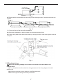
7
Condensate
hose(accessory)
Below 500mm
Below 75mm
Fig. 9
◆
Please install the condensate hose according to the following process if several drain hoses join
together.
Above 4"
The specs of the joined condensate hoses should fit the running capacity of the unit.
Fig. 10
(2). Check the flow of the drain after installation
◆ Check drain operation by pouring water into unit and observing flow.
◆ Further verify drain setup and correct flow by running all indoor units when system install is
complete.
Fig.11
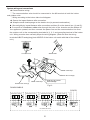
2.8 Electrical wiring
Note:The operating voltage of the indoor unit comes from the outdoor unit
terminal block.
◆ For information about the electrical wiring, please see the wiring diagram included
with the unit.
◆
All electrical wiring must be done by a certified technician.
◆ Ensure all ground wiring is securely connected.

8
◆ Communication wiring:
①
The communication wire should be connected to the #2 terminal at both the indoor
and outdoor units.
②
Wiring according to the indoor side circuit diagram.
◆ Secure the impact fastener after connection.
◆ Wrap the small-sized sponge on the electric wire (to prevent condensation).
◆ Secure tightly by impact fastener after connection and then fit on the electric box (1) and (2).
◆ Connect the 4-conductor rubber wire through the hole of the chassis and the bottom of
the appliance upward, and then connect the power line and the communication line from
the outdoor unit to the corresponding terminals N(1), 2, 3, and grounding terminal of the indoor
unit. Wiring must be done correctly as per the wiring diagram. (Note: Be sure the wiring
terminals A/B/C/D and piping joints A/B/C/D of the indoor unit match with that of the outdoor
unit.)
To indoor unit
To indoor unit
Stress relief
Cable-cross loop
Cable-cross loop
Seal here to prevent
Electric box cover(2)
water leakage
Fig.12
Electric box cover(1)
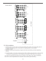
DHW36CMB21S
POWER
INDOOR UNIT D
INDOOR UNIT C
INDOOR UNIT B
INDOOR UNIT A
XT
XT XT2
OUTDOOR UNIT
N
L
System wiring and connections

9
DHW42CMB21S
POWER
INDOOR UNIT AINDOOR UNIT BINDOOR UNI
T CINDOOR UNIT D
OUTDOOR UNI
T
INDOOR UNIT E
XT2
XT1
XT3
XT4
XT5
XT6
N
L
G
G
G
G
G
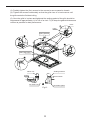
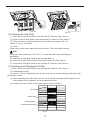
2.9 Grille Installation
1.
Install the grille onto the indoor unit body by matching the position of the swing flap motor of
2.
Install the cassette grille temporarily using the two hooks and latches provided at opposing
corners.
(1). Install the panel on the indoor unit temporarily. When installing, hang the latch on the hook that
is located on the opposite side of the swing flap on the panel of the indoor unit (2 places).
(2). Hang the remaining two latches onto the hooks on the sides of the indoor unit.(Ensure
there are no wires caught between the cassette chassis and the grille assembly.)
the panel to the piping position of the panel to the piping position of the cassette
as shown in Fig.13.

10
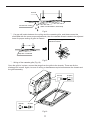
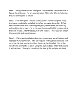
(3).
Partially tighten the (four) screws in the corners to secure panel to chassis.
(4). Tighten the screws incrementally so that the grille rises in a level manner until
the grille meets the finished ceiling.
(5). Once the grille is in place and tightened the sealing gasket of the grille should be
compressed to approximately 1/4 to 1/8 of an inch. Try to keep the gasket thickness as
uniform as possible for best performance.
Latch
Piping position
Swing flap motor
Indoor unit
Ceiling
Air outlet vent
Decorative panel
5mm to 8mm
Sealing material
Hook
Fig.13

11
Air leak
Air leak from ceiling
Water condensatation, water drop
Fig.14
②
.
If a gap still exists
between the ceiling
and the cassette grille, and these cannot be
eliminated with the corner screw adjustments, then the cassette chassis needs to be adjusted
lower for proper sealing of grille to chassis
Corner adjustment(s) to lower the
chassis if needed.
Gaps are not allowed
Fig.15
③
.
Wiring of the cassette grille (Fig.16)
Once the grille is in place, connect the plugs from the grille to the chassis. These are for the
discharge air louvers. Again, be sure no wiring or harnesses are pinched between the chassis and
the grille assembly.
At body At pane
At body At pane
Fig.16

12
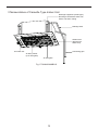
3
Nomenclature of Cassette Type Indoor Unit
Air outlet vent
Air filter, purifier
(in air inlet grille)
Air inlet grille
Guide louver
(placed in air
outlet vent)
Drainage equipment (inside type)
Discharge condensate water from
indoor unit when cooling
Connecting pipe
Drainage hose
Fig.17 DHMW24NKB21S
Page is loading ...
Page is loading ...
Page is loading ...
Page is loading ...
Page is loading ...
Page is loading ...
Page is loading ...
Page is loading ...
-
 1
1
-
 2
2
-
 3
3
-
 4
4
-
 5
5
-
 6
6
-
 7
7
-
 8
8
-
 9
9
-
 10
10
-
 11
11
-
 12
12
-
 13
13
-
 14
14
-
 15
15
-
 16
16
-
 17
17
-
 18
18
-
 19
19
-
 20
20
-
 21
21
-
 22
22
-
 23
23
-
 24
24
-
 25
25
-
 26
26
-
 27
27
-
 28
28


Johnson Controls M Series Owner's manual
- Category
- Split-system air conditioners
- Type
- Owner's manual
- This manual is also suitable for
Ask a question and I''ll find the answer in the document
Finding information in a document is now easier with AI
Related papers
-
Johnson Controls DHMW09NCB21S Owner's manual
-
York DHR18NCB21S Installation guide
-
Johnson Controls M Series Multi Zone System Installation guide
-
York DCX12CSB11S Installation guide
-
-
-
-
-
-
Other documents
-
-
-
-
-
-
-
-
 Venti Air HFG1212 Operating instructions
-
-
