Page is loading ...

861 AUXILIARY POWER DISTRIBUTION
AND BUS MODULE
Installation Guide
DESCRIPTION
MODEL
861
R B R B
RED PWR OUT BLK GND OUT
4-WIRE
BUS-A
RED
PWR IN
BLK
GND IN
4-WIRE
BUS-B
The Model861Auxiliary Power
Distribution and Bus Module
provides multiple auxiliary
power terminals and additional
Keypad Bus or LX‑Bus
connectors for a clean install.
The861Module is compatible with
all DMP XT30/XT50Series and
XR150/XR550Series panels, as well
as panels from other manufacturers.
For maximum flexibility, the
module is rated for either12VDC
or24VDC power input with a
maximum current handling capacity
of8Amps on the module RED PWR
IN and BLK GND IN terminals.
Compatibility
• XT30/XT50Series panels
• XR150/XR550Series panels
What is Included?
• One861Module
• One Pair of18AWG Red and
Black Wires (8”)
• One Model330 Dual‑Ended
4‑Wire Harness
• Hardware Pack
1
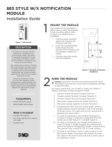
MOUNT THE MODULE
Themodule can be mounted in a DMP enclosure using the
standard3‑hole mounting pattern. Refer to Figure 2 as needed
during installation.
1. Hold the plastic standos against the inside of the enclosure
side wall.
2. Insert the included Phillips head screws from the outside of
the enclosure into the standos. Tighten the screws.
3. Carefully snap the module onto the standos.
Figure 1: 861 Module
Figure 2: Stando and Module Installation
BACK
1
2
3

Designed, engineered, and
manufactured in Springfield, MO
using U.S. and global components.
LT-0795 20105
861 AUXILIARY POWER
DISTRIBUTION AND
BUS MODULE
Ordering Information
860 Power Distribution/4 Wire Bus Module
Accessories
330 Dual-Ended 4-Wire Harness
Compatibility
XT30/XT50 Series Panels
XR150/XR550 Series Panels
MODEL
861
R B R B
RED PWR OUT BLK GND OUT
4-WIRE
BUS-A
RED
PWR IN
BLK
GND IN
4-WIRE
BUS-B
INTRUSION • FIRE • ACCESS • NETWORKS
2500 North Partnership Boulevard
Springfield, Missouri 65803-8877
800.641.4282 | DMP.com
© 2020
WIRE THE MODULE
2
The861Module provides8connections to the panel LX‑Bus or Keypad Bus. For example, connect Bus‑A to
the LX‑Bus and Bus‑B to the Keypad Bus. To configure all861Module headers to operate as only LX‑Bus or
Keypad Bus connections, join Bus‑A and Bus‑B together with the provided Model330harness.
Caution: Disconnect all power from the panel before wiring the module. Observe polarity on all
connections. Failure to do so may result in equipment damage or personal injury.
Refer to Figure 3 during wiring.
1. If necessary, join the module buses with the provided Model 330 harness. Connect themodule buses to
the panel.
2. Wire the861RED PWR IN and BLK GND IN Terminals to the panel Keypad Bus or to505‑12DC
terminals.
3. Connect2‑wire devices tomoduleRED PWR OUT and BLK GND OUT as needed.
MODEL
861
RED PWR OUT
To Panel
Keypad Bus
or 505-12
Power Supply
BLK GND OUT
RED
PWR IN
BLK
GND IN
R B
4-WIRE
BUS-B
R B
4-WIRE
BUS-A
RED
BLK
BLK
RED
To LX-Bus or
Keypad Bus
Max 8 Amps
2-Wire Device
Positive
2-Wire Device
Negative
12 VDC or 24 VDC
Bus-A and Bus-B
provide 8 LX-Bus
connections and
8 Keypad Bus
connections. To
configure all headers
to operate as only
Keypad Bus or LX-Bus
connections, wire
Bus-A and Bus-B
together with the
Model 330 harness.
Figure 3: Wiring Connections
/