Page is loading ...

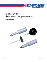
Model 3301C
Active Monopole Antenna
User Manual
Model 3301C Antenna Base

ii |
ETS-Lindgren Inc. reserves the right to make changes to any products herein to
improve functioning or design. Although the information in this document has
been carefully reviewed and is believed to be reliable, ETS-Lindgren does not
assume any liability arising out of the application or use of any product or circuit
described herein; nor does it convey any license under its patent rights nor the
rights of others. All trademarks are the property of their respective owners.
© Copyright 2009–2020 by ETS-Lindgren L.P. All Rights Reserved. No part
of this document may be copied by any means without written permission
from ETS-Lindgren Inc.
Trademarks used in this document: The ETS-Lindgren logo is a trademark of
ETS-Lindgren Inc.
Revision Record
MANUAL,3301C ACTIVE ROD ANTENNA,USER | Part #399792, Rev. J
Revision Description Date
A Initial Release October, 2009
B Updated part numbers in
Replacement and
Optional Parts
December, 2009
C Updated monopole rod
element information
July, 2011
D Added battery shelf life
and storage information
November, 2016
E Added calibration fixture
information
September, 2018
F Added statement that
batteries should be
replaced every 2 years
November, 2018
G Corrected information on
MIL-STD-461 Kit
June, 2020
H Fixed typo July, 2020
J Added CISPR Adapter
information
December, 2020

| iii
Table of Contents
Notes, Cautions, and Warnings ................................................ v
General Notices .......................................................................... v
1.0 Introduction .......................................................................... 7
Standard Configuration .................................................................................. 8
Antenna Base ........................................................................................ 8
Monopole Element ................................................................................. 9
Counterpoise ....................................................................................... 10
Rechargeable AA Nickel-Metal Hydride batteries (8) .......................... 10
MIL-STD-461F/G ................................................................................. 10
Test Kit ................................................................................................. 10
4-TR Light Tripod (Sold Separately) ............................................................ 11
ETS-Lindgren Product Information Bulletin ................................................. 12
2.0 Maintenance ....................................................................... 13
Battery Replacement ................................................................................... 13
Annual Calibration ....................................................................................... 16
Replacement and Optional Parts ................................................................. 16
Replacement Parts .............................................................................. 16
Optional Parts (each sold separately).................................................. 17
Service Procedures ..................................................................................... 17
3.0 Specifications ..................................................................... 19
Operational Specifications ........................................................................... 19
Table of Acceptable Pulse Repetition Rates ....................................... 20
Electrical Specifications ............................................................................... 21
Physical Specifications ................................................................................ 21
AC Adapter & Battery Specifications ........................................................... 22
4.0 Assembly Instructions ...................................................... 23
Counterpoise and Monopole Element ......................................................... 23
MIL-STD-461F/G Test Kit ............................................................................ 28
5.0 Mounting Instructions ....................................................... 31
4-TR Light Tripod Mounting Options (Sold Separately) ............................... 31
7-TR and Mast Mounting Options (Sold Separately) ................................... 32

iv |
2x2 Boom Mounting Options (Sold Separately) ........................................... 33
6.0 Operation ............................................................................ 35
Front Panel Controls and Indicators ............................................................ 35
Charge Status LED .............................................................................. 35
Charger Connector .............................................................................. 36
Saturation LED .................................................................................... 36
Output Connector ................................................................................ 37
Power LED ........................................................................................... 37
Power Switch ....................................................................................... 37
DIP Switches ............................................................................................... 38
For Internal Attenuation / Low Frequency Roll Off .............................. 38
Alarm DIP Switches ............................................................................. 40
Change DIP Switch Settings................................................................ 41
Charging the Batteries ................................................................................. 42
7.0 Calibrating the Model 3301C ............................................. 43
Calibration Steps ......................................................................................... 43
Model 3301 Calibration With Receiver and Signal Generator ..................... 46
Model 3301 Calibration With Network Analyzer .......................................... 47
Example of Antenna Factors Calculation with 1 meter Monopole ............... 48
8.0 Data and Illustrations ........................................................ 49
Periodic Rectangular Pulse Train ................................................................ 49
Spectrum of Rectangular Pulse ................................................................... 50
Altering Pulse Width / Pulse Repetition Rate ............................................... 51
Active Electric Field Antenna Calibration Fixture ......................................... 52
Active Monopole Antenna Calibration Setup ............................................... 53
Typical Curves–Typical Antenna Factors at the Default Switch Position
(All Off) ......................................................................................................... 54
Typical Curves–Typical Maximum Noise Voltage Using 10 Hz Bandwidth . 55
Typical Curves–Typical Minimum Discernable Electric Field Levels
(dB uV/m) Under Different Bandwidths ........................................................ 56
Typical Antenna Factors for Different Switch Configurations ...................... 57
Appendix: EC Declaration of Conformity .............................. 59

| v
Notes, Cautions, and Warnings
Note: Denotes helpful information intended to
provide tips for better use of the product.
Caution: Denotes a hazard. Failure to follow
instructions could result in minor personal injury
and/or property damage. Included text gives proper
procedures.
Warning: Denotes a hazard. Failure to follow
instructions could result in SEVERE personal injury
and/or property damage. Included text gives proper
procedures.
See the ETS-Lindgren Product Information Bulletin for safety,
regulatory, and other product marking information.
General Notices
FCC Certifications
This equipment has been tested and found to
comply with the limits for a Class A digital device,
pursuant to part 5 of the FCC Rules.
See the ETS-Lindgren Product Information Bulletin for safety,
regulatory, and other product marking information.

vi |
This page intentionally left blank.

Introduction | 7
1.0 Introduction
The ETS-Lindgren
Model 3301C Active
Monopole Antenna is a
broadband, high sensitivity
electric-field receiving
antenna. The Model 3301C is
composed of:
Monopole element
Counterpoise
Broadband, high input
impedance preamplifier
The monopole and
counterpoise function
together as an electrically
short antenna over ground
plane. The preamplifier
provides impedance
transformation from the high
impedance at the base of the
monopole to the 50 ohms
required by most receiving
systems, and provides power
gain to allow the sensing of
low-level signals.
The Model 3301C is designed to provide reception of an electric field in a signal
band without tuning or band switching from 30 Hz to 50 MHz. The 3 dB roll off
points for the antenna factor are at 170 Hz and 30 MHz. Between 250 Hz and
20 MHz, the antenna factor is flat within +/- 1 dB. Despite the roll of the antenna
factor, the usable range is 30 Hz to 50 MHz.
Includes:
BNC cable
BNC bulkhead connector
Ferrite bead
Right-angle bracket

8 | Introduction
The Model 3301C is designed for maximum sensitivity and dynamic range, and is
capable of sensing fields of 7 dBuV/m at 1 MHz with a 1 kHz bandwidth.
However, it will not saturate below field strength of 0.8 V/m. As a result, the unit
provides a wide dynamic range of 111 dB nominal at mid-band. In addition, at
10 dB and 30 dB (+/-10%), internal attenuators enable the Model 3301C to be
used in fields up to 25 V/m, expanding the dynamic range to 141 dB. A saturation
indicator provides an alert to the need for internal attenuators.
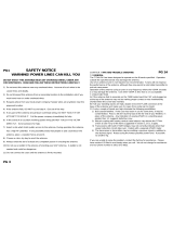
Standard Configuration
ANTENNA BASE
Includes built-in preamplifier and BNC (output) connector. Base is
drilled to accept ETS-Lindgren or other tripod mount with standard
1/4–20 threads.
Four thumbscrew knobs used to secure the counterpoise to the metal
grounding strips on the top of the antenna base are shipped attached
to the grounding strips (thumbscrews not shown in photo).
For a complete description of the Model 3301C controls, switches, and indicator
lights, see Operation on page 35.

Introduction | 9
MONOPOLE ELEMENT
The monopole element includes these parts for assembly:
(1) 116474 Rod section without antenna adapter
(1) 116474 Rod section with antenna adapter
(1) 116862 Center section
The monopole may be assembled as follows:
For a finished length of 40.95 in (1040 mm)—Assemble all parts,
including the 116862 center section.
For a finished length of 39.37 in (1000 mm)—Assemble all parts
except for the 116862 center section.
See page 26 for the steps to assemble the monopole.

10 | Introduction
COUNTERPOISE
The two halves assemble into a
24 in by 24 in square (60.96-cm
square).
To extend the ground plane, the
counterpoise may be attached
to a workbench using the holes
around the perimeter of the
counterpoise.
RECHARGEABLE AA NICKEL-METAL HYDRIDE BATTERIES (8)
The Model 3301C is shipped with 8 Nickel-Metal Hydride (NiMH) batteries installed.
The batteries are rechargeable, and include an AC adapter for charging. You must
charge the batteries before using the Model 3301C for the first time. See Charging the
Batteries on page 42 for more information.
MIL-STD-461F/G
TEST KIT
To comply with the standard,
the MIL-STD-461F/G Test Kit
includes a 27-in BNC cable,
BNC bulkhead connector, ferrite
bead, and a right-angle bracket.
For information on using the kit,
see page 28.

Introduction | 11
4-TR Light Tripod (Sold Separately)
ETS-Lindgren offers the non-metallic, non-reflective 4-TR Light Tripod for use at
both indoor and outdoor EMC test sites.
Constructed of linen phenolic and
delrin, designed with an adjustable
center post for precise height
adjustments.
Maximum height is 1.00 m
(39.37 in), and minimum height is
0.50 m (19.68 in). This tripod can
support up to a 2.27 kg (5.0 lb)
load.
Model 3301C shown mounted
with MIL-STD-461F/G Test Kit
onto 4-TR Light Tripod

12 | Introduction
ETS-Lindgren Product Information Bulletin
See the ETS-Lindgren Product Information Bulletin included with your shipment
for the following:
Safety, regulatory, and other product marking information
Steps to receive your shipment
Steps to return a component for service
ETS-Lindgren calibration service
ETS-Lindgren contact information

Maintenance | 13
2.0 Maintenance
Before performing any maintenance,
follow the safety information in the
ETS-Lindgren Product Information
Bulletin included with your shipment.
Maintenance of the Model 3301C is
limited external components such as
cables or connectors.
Clean the exterior of the cabinet using a
damp cloth and mild cleaner. Always
unplug the unit before cleaning.
If you have any questions concerning
maintenance, contact ETS-Lindgren
Customer Service.
Battery Replacement
At end of useful life, please recycle the used batteries, or dispose of
them safely and properly. Many cities collect used batteries for
recycling or disposal. You may contact your local waste disposal
agency for information on battery recycling and disposal.
If the unit may be idle (shelved and unused) for more than a month,
remove the batteries and store them separately. Check them before
reinstalling them in the unit and install fresh batteries if necessary.
ETS-Lindgren recommends replacing the battery every two years.
1. Place the power switch in the OFF/CHG position. See Operation on
page 35 for information on the front panel controls and indicators.
2. Remove the monopole element and counterpoise. See Counterpoise
and Monopole Element on page 23 for more information.
WARRANTY

14 | Maintenance
3. Disconnect all cables from the antenna base.
4. Turn over the Model 3301C antenna base and place it on a stable
surface with the bottom facing up.
5. Use a Phillips screwdriver to remove the eight screws from around the
perimeter of the base, and then lift the lid to remove it from the base.
6. Lift and remove each battery from the battery holder.

Maintenance | 15
7. Insert one new battery into each battery holder, matching the
–/+ on the battery with the –/+ on the board. Slide the + end of the
battery into the appropriate end of the holder, and then press the
– end of the battery down until the entire battery is secure in the
holder.
TIP: To assist in inserting the battery into the holder, you might need
to pull the contacts slightly outward.
8. Replace the lid on the base, and insert and tighten the screws. Do not
over tighten.
For maximum battery life, fully charge the batteries before placing
them into service for the first time. Failing to fully charge the batteries
may result in reduced battery life and cause premature battery failure.
9. See page 42 for the steps to charge the new batteries.

16 | Maintenance
Annual Calibration
See the Product Information Bulletin included with your shipment for information
on ETS-Lindgren calibration services.
Replacement and Optional Parts
ETS-Lindgren may substitute a similar part or new part number with
the same functionality for another part/part number. Contact
ETS-Lindgren for questions about part numbers and ordering parts.
Following are the part numbers for ordering replacement or optional parts for the
Model 3301C Active Monopole Antenna.
REPLACEMENT PARTS
Part Description Part Number
Monopole Element
116476 Monopole,
entire assembly
116474 Rod section without
antenna adapter
116862 Center section
Note: 116474 Rod section with antenna adapter is not a replaceable part; if
you need that section, you will need to order the entire monopole assembly,
116476.
Counterpoise, Half (2) 114670
Knobs, Counterpoise (4) 910051
AC Adapter H-30DTS050
Rechargeable AA NiMH Batteries,
2000 mAh (8)
400042
Cordset, 6 ft, IEC 320-C7 to NEMA 5-15 670059

Maintenance | 17
O
PTIONAL PARTS (EACH SOLD SEPARATELY)
Part Description Part Number
3301C Calibration Fixture (10pF) 3301CAL–A
3301C Calibration Fixture (12pF)* 3301CAL–B*
Tripod, Non-Conductive,1M, Light 4-TR,1ML
3301C CISPR Adapter
†
119814
†
*Required in order to meet CISPR 16-1-6: 2017 and ANSI 63.5: 2017
†
Decouples the coax ground from the chassis for CISPR testing.
Service Procedures
For the steps to return a system or system component to ETS-Lindgren for
service, see the Product Information Bulletin included with your shipment.

18 | Maintenance
This page intentionally left blank.

Specifications | 19
3.0 Specifications
Operational Specifications
Frequency Range: 30 Hz to 50 MHz
(maximum usable bandwidth)
Low Frequency Roll Off: The low frequency roll off is
switch-selectable to be 3 dB down at
22 kHz, 1.9 kHz, or 170 Hz.
High Frequency Roll Off: Antenna factor is 3 dB down at 30 MHz
Antenna Factor:
See data chart on page 54.
Unless otherwise noted, the low
frequency roll off is set at the 170 Hz
3 dB roll off point
Saturation Level:
0.8 V/m narrowband without attenuation
25 V/m with 30 dB of internal attenuation
selected
63 dBuV/m/MHz broadband saturation
level
Minimum Discernible
Signal:
See data chart on page 56.
For best sensitivity all internal
attenuation should be turned off
Dynamic Range:
111 dB at mid-band (1 MHz)
141 dB with the use of the internal
attenuators

20 | Specifications
Saturation Indicator
Impulse Response:
The saturation indicator will properly
indicate saturation for pulsed signals which
fall within the following boundaries:
The product of the pulse width to pulse
repetition rate must be greater than
0.003.
The pulse repetition rate must be less
than value listed for the applicable duty
cycle. See the following Table of
Acceptable Pulse Repetition Rates.
TABLE OF ACCEPTABLE PULSE REPETITION RATES
Duty Cycle Maximum PRF
10 19.7 MHz
20 14.0 MHz
30 9.2 MHz
40 5.6 MHz
50 420.0 kHz
60 130.0 kHz
70 87.0 kHz
80 57.0 kHz
90 30.0 kHz
/