Page is loading ...

714-D22 Zone Expander Module
Description
The 714-D22 zone expander module allows you to increase the number of reporting zones available on DMP panels.
Refer to the panel installation guide for more information about the maximum number and type allowed per panel.
The modules connect to the panel’s 4-wire keypad bus or LX-Bus™ and are set to an address that determines the
reporting zone number. The 714-D22 provides four Class B, Style A zones for use with burglary devices.
Zone Programming
Program the zones on the zone expander module with any of the panel burglary zone types or as an Arming type
zone when used with keyswitches.
Zone Expander Data LED
The LED on the zone expander ashes each time the module responds to a poll from the panel. If there is a problem
with the panel, panel programming, or the Green data wire between the panel and the zone expander module, the
LED stops ashing.
Installing the 714-D22 Module
Mount the module outside the panel enclosure in the housing on a at surface such as a wall or single-gang box.
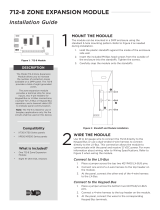
714-D22 Zone Wiring
This module uses a wire harness for wiring connections. Figure 1 shows the zone colors and polarity. You may use an
optional 718T Plug-in Screw Terminal that plugs into the 714-D22 to provide a screw type terminal connector for 14
to 22 gauge device wiring.
Wiring the 714-D22 Module
Connect the Red, Green, Yellow, and Black wires from the panel keypad bus or LX-Bus™ to the matching harness
wires on the 714-D22 Zone Expander.
C1
C4
U1
U2
CR3
TXD
J1
R
E
D
Tens Ones
714-D22
Module
To Keypad Bus or LX-Bus
White/Yellow - Zone 4
White/Orange - Zone 3
White/Red - Zone 2
White/Brown - Zone 1
Black
Green
Yellow
Red
714-D22 Module -
Connect Red to LX-Bus Wire or Panel Terminal 7
714-D22 Module - install 1k EOL
+
–
+
–
+
–
+
–
All zones are supervised
The maximum zone line impedance is 100 Ohms
714-D22: Zone Ground Fault detected at 1500 Ohms or less
The normal operating range is:
714-D22 650 - 1900 Ohms
Figure 1: 714-D22 Wiring Diagram
InstallatIon GuIde

Digital Monitoring Products 714/715 Installation Guide
2
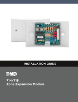
Setting Address Switches
714-D22 Zone Expanders use two rotary switches (TENS and ONES) to set the module address. For keypad bus
addresses, set the switches to match the device address. For LX-Bus addresses, set the switches to match the last
two digits of the addresses. For example, for address 02 set the switches to TENS = 0 and ONES = 2 as shown in
Figure 2.
0
1
2
3
4
5
6
7
8
9
S2
0
1
2
3
4
5
6
7
8
9
S1
TENS ONES
Figure 2: Switches
Keypad Bus Zone Numbers
Refer to Table 1 for keypad bus zone numbers and the panels where they operate.
Keypad
Bus
Address
Switches
Tens Ones
XT30/XT50 XR100 Series XR500 Series
1 0 1 11 to 14 11 to 14 11 to 14
2 0 2 21 to 24 21 to 24 21 to 24
3 0 3 31 to 34 31 to 34 31 to 34
4 0 4 41 to 44 41 to 44 41 to 44
5 0 5 51 to 54 51 to 54 51 to 54
6 0 6 61 to 64 61 to 64 61 to 64
7 0 7 71 to 74 71 to 74 71 to 74
8 0 8 81 to 84 81 to 84 81 to 84
9 0 9 N/A N/A 91 to 94
10 1 0 N/A N/A 101 to 104
11 1 1 N/A N/A 111 to 114
12 1 2 N/A N/A 121 to 124
13 1 3 N/A N/A 131 to 134
14 1 4 N/A N/A 141 to 144
15 1 5 N/A N/A 151 to 154
16 1 6 N/A N/A 161 to 164
Table 1: Keypad Bus Zone Numbers

714/715 Installation Guide Digital Monitoring Products
3
LX-Bus Zone Numbers
The 714-D22 module provides 4 zones. When set to an address, the module uses four zone numbers. For example,
setting the module to the LX-Bus address 502 (TENS = 0, ONES = 2) sets the module zone numbers to 502, 503, 504,
and 505.
Refer to Table 2 for a partial listing of XR100/XR500 Series panel LX-Bus zone numbers.
Note: XR100 Series panels only use LX-Bus number one.
LX-Bus
Address
LX-Bus
Number
Switches
Tens Ones
Zone
Numbers
501 1 0 1 501 to 504
506 1 0 6 506 to 509
623 2 2 3 623 to 626
654 2 5 4 654 to 657
742 3 4 2 742 to 745
768 3 6 8 768 to 771
833 4 3 3 833 to 836
877 4 7 7 877 to 880
919 5 1 9 919 to 922
994 5 9 4 994 to 997
Table 2: LX-Bus Zone Numbers
Optional Accessories
You can replace the standard wiring harness with the optional 718T Plug-in Screw Terminal. The enclosure base can
also accommodate the 719T Terminal Boards for the 714-D22, which passes through the panel LX-Bus wiring. The
719T includes 1k EOL resistors.
Wiring Specications for Keypad and LX-Bus
1. DMP recommends using 18 or 22-gauge unshielded wire for all keypad and LX-Bus circuits. Do Not use twisted
pair or shielded wire for LX-Bus and keypad bus data circuits. To maintain auxiliary power integrity when
using 22-gauge wire do not exceed 500 feet. When using 18-gauge wire do not exceed 1,000 feet. Install an
additional power supply to increase the wire length or add devices.
2. Maximum distance for any one circuit (length of wire) is 2,500 feet regardless of the wire gauge. This distance
can be in the form of one long wire run or multiple branches with all wiring totaling no more than 2,500 feet.
As wire distance from the panel increases, DC voltage on the wire decreases.
3. Maximum number of devices per 2,500 feet circuit is 40.
Note: Each panel allows a specic number of supervised keypads. Add additional keypads in the unsupervised
mode. Refer to the panel installation guide for the specic number of supervised keypads allowed.
4. Maximum voltage drop between the panel (or auxiliary power supply) and any device is 2.0 VDC. If the voltage
at any device is less than the required level, add an auxiliary power supply at the end of the circuit. When
voltage is too low, the devices cannot operate properly.
For additional information refer to the panel installation guide and LX-Bus/Keypad Bus Wiring Application Note
(LT-2031) or the 710 Installation Guide (LT-0310).

LT-1271 © 2013 Digital Monitoring Products, Inc.
2500 North Partnership Boulevard
800-641-4282
www.dmp.com
13385
Specications
Operating Voltage 12 VDC
Operating Current
714-D22 7mA + 1.6mA per zone
Zone Voltage
5 VDC, max 2mA
Dimensions 4.5” H x 2.75” W x 1.75” D
Zones Four Supervised Class B
Style A Power Limited
Accessories
718T Plug-in Screw Terminal
719T Terminal Boards
Compatibility
The 714-D22 is compatible with the following
panels:
XR100/XR500 Series and XT30/XT50 Series
/