Page is loading ...


2 Installation and maintenance instructions ecoFIT pure 0020230533_07
Installation and maintenance
instructions
Contents
1 Safety .................................................................... 3
1.1 Intended use.......................................................... 3
1.2 Qualification........................................................... 3
1.3 General safety information .................................... 3
1.4 Regulations (directives, laws, standards) .............. 5
1.5 List of relevant standards for Great Britain and
Ireland.................................................................... 5
2 Guarantee and Customer Service...................... 6
3 Technical data...................................................... 7
4 Notes on the documentation ............................ 11
5 Product description........................................... 11
5.1 CE marking.......................................................... 11
5.2 Hot Water Association ......................................... 11
5.3 Information on the identification plate.................. 11
5.4 Functional elements: System boiler..................... 12
5.5 Safety Devices..................................................... 12
6 Set-up.................................................................. 13
6.1 Checking the scope of delivery............................ 13
6.2 Dimensions.......................................................... 13
6.3 Installation site..................................................... 14
6.4 Minimum clearances............................................ 14
6.5 Compartment Ventilation ..................................... 14
6.6 Air/flue pipe.......................................................... 14
6.7 Using the mounting template............................... 17
6.8 Wall-mounting the product................................... 17
6.9 Removing/installing the front casing.................... 18
6.10 Removing/installing the side section ................... 18
7 Installation.......................................................... 19
7.1 Preparing for installation...................................... 19
7.2 Descaling the water ............................................. 19
7.3 Check compliance with the local gas group ........ 19
7.4 Gas and water connections ................................. 19
7.5 Connecting the drain pipework for the
expansion relief valve .......................................... 19
7.6 Connecting the condensate discharge pipe ........ 20
7.7 Flue installation.................................................... 22
7.8 Electrical installation ............................................ 22
8 Operation............................................................ 25
8.1 Operating concept ............................................... 25
8.2 Installer level overview......................................... 25
8.3 Calling up the installer level................................. 25
8.4 Live Monitor (status codes) ................................. 25
8.5 Using check programmes.................................... 25
9 Start-up ............................................................... 26
9.1 Carrying out the initial start-up............................. 26
9.2 Checking and treating the heating water/filling
and supplementary water .................................... 26
9.3 Filling the condensate trap .................................. 27
9.4 Switching on the product ..................................... 27
9.5 Avoiding danger arising from insufficient water
pressure............................................................... 27
9.6 Flushing the heating installation for the first
time ("cold") ......................................................... 27
9.7 Filling and purging the heating installation .......... 27
9.8 Filling the domestic hot water circuit.................... 28
9.9 Checking the gas setting ..................................... 28
9.10 Thoroughly flushing the heating installation
("hot")................................................................... 29
9.11 Checking leak-tightness ...................................... 30
10 Adapting the unit to the heating
installation.......................................................... 30
10.1 Setting the burner anti-cycling time ..................... 30
10.2 Setting the pump output....................................... 30
10.3 Setting the bypass valve...................................... 31
10.4 Setting the domestic hot water temperature........ 32
11 Handing over to the end user........................... 32
12 Inspection and maintenance ............................ 33
12.1 Complete Service Interval Record section .......... 33
12.2 Using original seals.............................................. 33
12.3 Observing inspection and maintenance
intervals ............................................................... 33
12.4 Checking the CO₂ content ................................... 33
12.5 Setting the CO₂ content ....................................... 33
12.6 Removing the gas-air mixture unit....................... 33
12.7 Cleaning the heat exchanger............................... 34
12.8 Checking the burner ............................................ 34
12.9 Checking the ignition electrode ........................... 34
12.10 Cleaning the condensate trap.............................. 35
12.11 Installing the gas-air mixture unit......................... 35
12.12 Draining the product ............................................ 35
12.13 Checking the pre-charge pressure of the
expansion vessel ................................................. 35
12.14 Completing inspection and maintenance work .... 35
13 Troubleshooting ................................................ 35
13.1 Eliminating faults.................................................. 35
13.2 Calling up and clearing the fault memory ............ 36
13.3 Resetting parameters to factory settings ............. 36
13.4 Preparing the repair work .................................... 36
13.5 Replacing defective components......................... 36
13.6 Checking the product for leak-tightness .............. 38
14 Decommissioning the product ......................... 38
15 Recycling and disposal..................................... 39
Appendix ............................................................................ 40
A Inspection and maintenance work................... 40
B Overview of diagnostics codes........................ 41
C Status codes – Overview .................................. 45
D Overview of fault codes .................................... 46
E Wiring diagram: system boiler ......................... 48
F Wiring diagram: system boiler (30 kW) ........... 49
G Commissioning Checklist................................. 50
H Commissioning Flow Chart .............................. 54
Index ................................................................................... 55

0020230533_07 ecoFIT pure Installation and maintenance instructions 3
1 Safety
1.1 Intended use
The product is intended as a heat generator
for closed heating installations and for do-
mestic hot water generation.
Improper use of any kind is prohibited.
Intended use also includes the following:
– use of the product only in mobile homes
that are made, transported once and per-
manently situated in Great Britain and Ire-
land. After the transportation of the mo-
bile home to its destination the complete
product must be checked for leak-tightness
again
– validity of the product only for Great Britain
and Ireland and for the gas types in Great
Britain and Ireland as listed on the data
plate
– Installing and operating the product only
in conjunction with accessories for the
air/flue pipe which are listed in the other
applicable documents and comply with the
type of unit
– Using the product while observing the ac-
companying operating, installation and
maintenance instructions for the product
along with all other components of the in-
stallation
– Installing and setting up the product while
observing the product and system ap-
proval
– Observing all inspection and maintenance
conditions listed in the instructions
– Installing while observing the IP code
The following is classed as improper use:
– Using the product in vehicles, such as mo-
bile homes or caravans. Units that are not
classed as vehicles are those that are in-
stalled in a fixed and permanent location
(known as "fixed installation").
– Any direct use in industrial or commercial
processes
– Any use other than those described in
these instructions and any use that goes
beyond what is described here
1.2 Qualification
The person carrying out the work described
here must have completed professional train-
ing. The competent person must demon-
strably have all of the knowledge, skills and
capabilities that are required in order to carry
out the work mentioned below.
The following work must only be carried out
by competent persons who are sufficiently
qualified to do so:
– Set-up
– Dismantling
– Installation
– Start-up
– Inspection and maintenance
– Repair
– Decommissioning
▶ Proceed in accordance with current tech-
nology.
▶ Use the correct tool.
The above-mentioned work must always only
be carried out by persons with sufficient qual-
ifications.
This product can be used by children over
eight years old and also by persons with lim-
ited physical, sensory or mental capabilities
or insufficient experience and/or knowledge if
they are supervised or have been provided
with instructions on how to safely use the
product, and they understand the risks res-
ulting from using the product. Children must
not play with the product. Cleaning and user
maintenance work must not be carried out by
children unless they are supervised.
1.3 General safety information
The following sections convey important
safety information. It is essential to read and
observe this information in order to prevent
risk of death, risk of injury, material damage
or environmental damage.
1.3.1 Gas
If you smell gas:
▶ Avoid rooms that smell of gas.
▶ If possible, open doors and windows fully
and ensure adequate ventilation.
▶ Do not use naked flames (e.g. lighters,
matches).
▶ Do not smoke.

4 Installation and maintenance instructions ecoFIT pure 0020230533_07
▶ Do not use any electrical switches, mains
plugs, doorbells, telephones or other com-
munication systems in the building.
▶ Close the emergency control valve or the
main isolator.
▶ If possible, close the gas stopcock on the
product.
▶ Warn other occupants in the building by
yelling or banging on doors or walls.
▶ Leave the building immediately and ensure
that others do not enter the building.
▶ Notify the gas supply company or
the Emergency Service Provider
+44 (0) 800 111999 by telephone once you
are outside of the building.
1.3.2 Flue gas
Flue gases may cause poisoning, while hot
flue gases may also cause burns. Flue gases
must therefore never be allowed to escape
uncontrollably.
What to do if you smell flue gas in the prop-
erty:
▶ Open all accessible doors and windows
fully to provide ventilation.
▶ Switch off the product.
▶ Check the flue gas routes in the product
and the flue gas diversions.
To prevent flue gas exit:
▶ Only operate the product if the air/flue pipe
has been completely installed.
▶ With the exception of short periods for
testing purposes, only operate the product
when the front casing is installed and
closed.
▶ If you operate the product with an empty
condensate trap / siphon, then flue gas
may escape into the room air.
▶ In order to operate the product, ensure that
the condensate trap / siphon is always full.
To ensure that the seals are not damaged:
▶ Instead of grease, use only water or com-
mercially available soft soap to aid installa-
tion.
1.3.3 Electricity
The power supply terminals L and N remain
live even if the unit main switch is switched
off.
To prevent electric shocks, proceed as fol-
lows before working on the product:
▶ Disconnect the product from the power
supply by switching off all power supplies
at all poles (electrical partition with a con-
tact gap of at least 3 mm, e.g. fuse or cir-
cuit breaker) or remove the mains plug (if
present).
▶ Secure against being switched back on
again.
▶ Wait at least three minutes until the con-
densers have discharged.
▶ Check that there is no voltage.
1.3.4 Weight
To prevent injuries when transporting the
product:
▶ Make sure that the product is transported
by at least two people.
1.3.5 Explosive and flammable substances
To prevent explosions and fire:
▶ Do not use the product in storage rooms
that contain explosive or flammable sub-
stances (such as petrol, paper or paint).
1.3.6 High temperatures
To prevent burns:
▶ Only carry out work on components once
they have cooled down.
To prevent material damage that is caused
by heat transfer:
▶ Only solder connectors if the connectors
are not yet screwed to the service valves.
1.3.7 Heating water
Both unsuitable heating water and air in the
heating water may cause material damage to
the product and in the heat generator circuit.
▶ Check the quality of the heating water.
(→ Page 26)
▶ If you use non-diffusion-tight plastic pipes
in the heating installation, ensure that no
air gets into the heat generator circuit.
1.3.8 Neutralisation device
To prevent contamination of the waste water:
▶ Check whether a neutralising unit must
be installed in accordance with national
regulations.

0020230533_07 ecoFIT pure Installation and maintenance instructions 5
▶ Observe local regulations on neutralising
condensate.
1.3.9 Frost
To prevent material damage:
▶ Do not install the product in rooms prone
to frost.
1.3.10 Safety devices
▶ Install the necessary safety devices in the
installation.
1.4 Regulations (directives, laws,
standards)
▶ Observe the national regulations, stand-
ards, directives, ordinances and laws.
1.5 List of relevant standards for Great
Britain and Ireland
▶ Observe the national regulations, stand-
ards, directives, ordinances and laws.
You can find a list of relevant standards at:
https://www.vaillant.co.uk/standards

6 Installation and maintenance instructions ecoFIT pure 0020230533_07
2 Guarantee and Customer Service
Thank you for installing a new Vaillant appliance in your home.
Vaillant appliances are manufactured to the very highest standard so we are pleased to offer our
customers a comprehensive guarantee.
To maintain your guarantee, the boiler must be serviced annually by a competent person who
holds the required qualifications in accordance with the rules in force of the country where the
product is installed and in accordance with the manufactures recommendations.
We recommend you complete your guarantee registration as soon as possible.
Guarantee Registration
Sales Support:
Telephone: 0345 602 0262
Technical Enquiries:
Telephone: 0344 693 3133
Email: technical@vaillant.co.uk
General Enquiries:
Telephone: 0345 602 2922
Training Enquiries:
Telephone: 0345 601 8885
Email: training.enquiriesuk@vaillant-group.com
Spares Enquiries:
Telephone: 01773 596 615
To register your Vaillant appliance visit:
https://self-service.vaillant.co.uk/warranty-registration
Vaillant is a licensed member of the Benchmark Scheme. Benchmark places responsibilities on both manufacturers and installers.
The purpose is to ensure that customers are provided with the correct equipment for their needs, that it is installed, commissioned
and serviced in accordance with the manufacturer’s instructions by a competent person approved at the time by the Health and
Safety Executive and that it meets the requirements of the appropriate Building Regulations.
The Benchmark Checklist can be used to demonstrate compliance with Building Regulations and should be provided to the customer
for future reference.
Installers are required to carry out installation, commissioning and servicing work in accordance with the Benchmark Code of
Practice which is available from the Heating and Hotwater Industry Council who manage and promote the Scheme.
Benchmark is managed and promoted by the Heating and Hotwater Industry Council.

0020230533_07 ecoFIT pure Installation and maintenance instructions 7
3 Technical data
Technical data – General
VU 126/6-3 (H-GB) VU 156/6-3 (H-GB) VU 186/6-3 (H-GB) VU 256/6-3 (H-GB)
Gas category
I
2H
I
2H
I
2H
I
2H
Diameter of the gas pipe
1/2 inch 1/2 inch 1/2 inch 1/2 inch
Diameter of the heating connec-
tions
3/4 inch 3/4 inch 3/4 inch 3/4 inch
Expansion relief valve connection
pipe (min.)
15 mm 15 mm 15 mm 15 mm
Condensate discharge pipe (min.)
21.5 mm 21.5 mm 21.5 mm 21.5 mm
G20 gas supply pressure
2.0 kPa
(20.0 mbar)
2.0 kPa
(20.0 mbar)
2.0 kPa
(20.0 mbar)
2.0 kPa
(20.0 mbar)
Gas flow at P max. – hot water
(G20)
1.6 m³/h 1.9 m³/h 2.7 m³/h 3.2 m³/h
Gas flow at P max. – heating mode
(G20)
1.3 m³/h 1.6 m³/h 1.9 m³/h 2.7 m³/h
Gas flow at P min. (G20)
0.476 m³/h 0.480 m³/h 0.533 m³/h 0.648 m³/h
CE number (PIN)
CE-0063CP3646 CE-0063CP3646 CE-0063CP3646 CE-0063CP3646
SAP 2009/2012 annual efficiency
(%)
89.8 89.8 89.7 89.7
Flue gas mass rate in heating
mode at P min.
2.06 g/s 2.08 g/s 2.31 g/s 2.81 g/s
Flue gas mass rate in heating
mode at P max.
5.5 g/s 6.9 g/s 8.3 g/s 11.5 g/s
Flue gas mass rate in hot water
handling mode at P max.
6.9 g/s 8.3 g/s 11.6 g/s 13.8 g/s
Flue gas temperature (80 °C/60 °C)
at P max.
55 ℃ 55 ℃ 60 ℃ 77 ℃
Flue gas temperature (80 °C/60 °C)
at P min.
55 ℃ 55 ℃ 55 ℃ 55 ℃
Flue gas temperature (50 °C/30 °C)
at P max.
43 ℃ 48 ℃ 51 ℃ 62 ℃
Flue gas temperature (50 °C/30 °C)
at P min.
32 ℃ 32 ℃ 34 ℃ 35 ℃
Flue gas temperature in hot water
handling mode
71 ℃ 71 ℃ 69 ℃ 68 ℃
Flue gas temperature when over-
heating
105 ℃ 105 ℃ 105 ℃ 95 ℃
Released system types
C13, C33, C43, C53 C13, C33, C43, C53 C13, C33, C43, C53 C13, C33, C43, C53
Nominal efficiency at 80/60 °C
99.1 % 98.9 % 98.8 % 98.8 %
Nominal efficiency at 50/30 °C
104.0 % 104.0 % 104.0 % 104.0 %
Nominal efficiency at 40/30 °C
106.0 % 106.0 % 106.0 % 106.0 %
Nominal efficiency in partial load
operation (30%) at 40/30 °C
109.9 % 109.9 % 109.8 % 109.8 %
NOx class
6 6 6 6
Product dimensions, width
390 mm 390 mm 390 mm 390 mm
Product dimensions, depth
295 mm 295 mm 295 mm 295 mm
Product dimensions, height
702 mm 702 mm 702 mm 702 mm
Net weight
31 kg 31 kg 31 kg 32 kg
Weight when filled with water
35 kg 35 kg 35 kg 36 kg
VU 306/6-3 (H-GB)
Gas category
I
2H
Diameter of the gas pipe
1/2 inch
Diameter of the heating connec-
tions
3/4 inch
Expansion relief valve connection
pipe (min.)
15 mm

8 Installation and maintenance instructions ecoFIT pure 0020230533_07
VU 306/6-3 (H-GB)
Condensate discharge pipe (min.)
21.5 mm
G20 gas supply pressure
2.0 kPa
(20.0 mbar)
Gas flow at P max. – hot water
(G20)
3.8 m³/h
Gas flow at P max. – heating mode
(G20)
3.2 m³/h
Gas flow at P min. (G20)
0.762 m³/h
CE number (PIN)
CE-0063CP3646
SAP 2009/2012 annual efficiency
(%)
89.8
Flue gas mass rate in heating
mode at P min.
3.30 g/s
Flue gas mass rate in heating
mode at P max.
13.8 g/s
Flue gas mass rate in hot water
handling mode at P max.
16.1 g/s
Flue gas temperature (80 °C/60 °C)
at P max.
82 ℃
Flue gas temperature (80 °C/60 °C)
at P min.
56 ℃
Flue gas temperature (50 °C/30 °C)
at P max.
56 ℃
Flue gas temperature (50 °C/30 °C)
at P min.
37 ℃
Flue gas temperature in hot water
handling mode
75 ℃
Flue gas temperature when over-
heating
104 ℃
Released system types
C13, C33, C43, C53
Nominal efficiency at 80/60 °C
99.2 %
Nominal efficiency at 50/30 °C
104.0 %
Nominal efficiency at 40/30 °C
106.0 %
Nominal efficiency in partial load
operation (30%) at 40/30 °C
109.8 %
NOx class
6
Product dimensions, width
390 mm
Product dimensions, depth
295 mm
Product dimensions, height
702 mm
Net weight
32 kg
Weight when filled with water
36 kg
Technical data – G20 power/loading G20
VU 126/6-3 (H-GB) VU 156/6-3 (H-GB) VU 186/6-3 (H-GB) VU 256/6-3 (H-GB)
Maximum heat output
12 kW 15 kW 18 kW 25 kW
Effective output range (P)
at 40/30 °C
4.8 to 13.0 kW 4.8 to 16.2 kW 5.3 to 19.5 kW 6.5 to 27.0 kW
Effective output range (P)
at 50/30 °C
4.7 to 12.8 kW 4.7 to 15.9 kW 5.2 to 19.1 kW 6.4 to 26.5 kW
Effective output range (P)
at 80/60 °C
4.5 to 12.2 kW 4.5 to 15.2 kW 5.0 to 18.3 kW 6.1 to 25.4 kW
Domestic hot water heat
output (P)
4.4 to 15.0 kW 4.4 to 18.0 kW 4.9 to 25.2 kW 6.0 to 30.0 kW
Maximum heat input –
heating (Q max.)
12.3 kW 15.3 kW 18.4 kW 25.5 kW
Minimum heat input – heat-
ing (Q min.)
4.5 kW 4.5 kW 5.0 kW 6.1 kW

0020230533_07 ecoFIT pure Installation and maintenance instructions 9
VU 126/6-3 (H-GB) VU 156/6-3 (H-GB) VU 186/6-3 (H-GB) VU 256/6-3 (H-GB)
Maximum heat input – hot
water (Q max.)
15.3 kW 18.4 kW 25.7 kW 30.6 kW
Minimum heat input – hot
water (Q min.)
4.5 kW 4.5 kW 5.0 kW 6.1 kW
VU 306/6-3 (H-GB)
Maximum heat output
30 kW
Effective output range (P)
at 40/30 °C
7.6 to 32.4 kW
Effective output range (P)
at 50/30 °C
7.5 to 31.8 kW
Effective output range (P)
at 80/60 °C
7.1 to 30.2 kW
Domestic hot water heat
output (P)
7.1 to 35.0 kW
Maximum heat input –
heating (Q max.)
30.6 kW
Minimum heat input – heat-
ing (Q min.)
7.2 kW
Maximum heat input – hot
water (Q max.)
35.7 kW
Minimum heat input – hot
water (Q min.)
7.2 kW
Technical data – Heating
VU 126/6-3 (H-GB) VU 156/6-3 (H-GB) VU 186/6-3 (H-GB) VU 256/6-3 (H-GB)
Max. flow temperature adjustment
range (default setting: 75 °C)
10 to 80 ℃ 10 to 80 ℃ 10 to 80 ℃ 10 to 80 ℃
Maximum permissible pressure
0.25 MPa
(2.50 bar)
0.25 MPa
(2.50 bar)
0.25 MPa
(2.50 bar)
0.25 MPa
(2.50 bar)
Nominal water flow (ΔT = 20 K)
530 l/h 655 l/h 788 l/h 1,094 l/h
Nominal water flow (ΔT = 30 K)
353 l/h 436 l/h 525 l/h 729 l/h
Approximate value for the
condensate volume (pH value
between 3.5 and 4.0) at 50/30 °C
1.23 l/h 1.53 l/h 1.84 l/h 2.55 l/h
ΔP heating at nominal flow (ΔT =
20 K)
0.025 MPa
(0.250 bar)
0.025 MPa
(0.250 bar)
0.025 MPa
(0.250 bar)
0.025 MPa
(0.250 bar)
VU 306/6-3 (H-GB)
Max. flow temperature adjustment
range (default setting: 75 °C)
10 to 80 ℃
Maximum permissible pressure
0.25 MPa
(2.50 bar)
Nominal water flow (ΔT = 20 K)
1,102 l/h
Nominal water flow (ΔT = 30 K)
876 l/h
Approximate value for the
condensate volume (pH value
between 3.5 and 4.0) at 50/30 °C
3.06 l/h
ΔP heating at nominal flow (ΔT =
20 K)
0.025 MPa
(0.250 bar)
Technical data – Electrics
VU 126/6-3 (H-GB) VU 156/6-3 (H-GB) VU 186/6-3 (H-GB) VU 256/6-3 (H-GB)
Electrical connection
230 V / 50 Hz 230 V / 50 Hz 230 V / 50 Hz 230 V / 50 Hz
Built-in fuse (slow-blow)
T2/2A, 250V T2/2A, 250V T2/2A, 250V T2/2A, 250V
Max. electrical power consump-
tion
75 W 81 W 87 W 87 W
Standby electrical power con-
sumption
2 W 2 W 2 W 2 W
IP rating
IPX4D IPX4D IPX4D IPX4D

10 Installation and maintenance instructions ecoFIT pure 0020230533_07
VU 306/6-3 (H-GB)
Electrical connection
230 V / 50 Hz
Built-in fuse (slow-blow)
T2/2A, 250V
Max. electrical power consump-
tion
104 W
Standby electrical power con-
sumption
2 W
IP rating
IPX4D

0020230533_07 ecoFIT pure Installation and maintenance instructions 11
4 Notes on the documentation
▶ Always observe all operating instructions enclosed with
the installation components.
▶ Store these instructions and all other applicable docu-
ments for further use.
These instructions apply only to:
Product article number
Article number Gas Council
Number
VU 126/6-3 (H-GB)
ecoFIT pure 612
0010020395 41-694-03
VU 156/6-3 (H-GB)
ecoFIT pure 615
0010020396 41-694-04
VU 186/6-3 (H-GB)
ecoFIT pure 618
0010020397 41-694-05
VU 256/6-3 (H-GB)
ecoFIT pure 625
0010020398 41-694-06
VU 306/6-3 (H-GB)
ecoFIT pure 630
0010020399 41-694-07
5 Product description
5.1 CE marking
The CE marking shows that the products comply with the
basic requirements of the applicable directives as stated on
the declaration of conformity.
The declaration of conformity can be viewed at the manufac-
turer's site.
5.2 Hot Water Association
Vaillant is a full member of the Hot Water Association and
promotes the scheme in association with its cylinder range.
Details are available on the web site www.vaillant.co.uk
5.3 Information on the identification plate
The identification plate is mounted on the underside of the
product in the factory.
The identification plate keeps record of the country in which
the product is to be installed.
Information on the
identification plate
Meaning
Barcode with serial number
Information on the
identification plate
Meaning
Serial number For quality control purposes; 3rd and 4th
digits = year of production
For quality control purposes; 5th and 6th
digits = week of production
For identification purposes; 7th to 16th
digits = product article number
For quality control purposes; 17th to 20th
digits = place of manufacture
ecoFIT pure Product designation
2H, G20 – 2 kPa (20
mbar)
Factory setting for type of gas and gas
connection pressure
Cat. Unit category
Condensing techno-
logy
Efficiency class of the boiler in accord-
ance with EC Directive 92/42/EEC
Type: Xx3(x) Permissible flue gas connections
PMS Maximum water pressure in heating
mode
PMW Maximum water pressure in hot water
handling mode
V/Hz Electrical connection
W Max. electrical power consumption
IP Level of protection
Heating mode
Hot water generation
Pn Nominal heat output range in heating
mode
Pnc Nominal heat output range in heating
mode (condensing technology)
P Nominal heat output range in hot water
handling mode
Qn Nominal heating load range in heating
mode
Qnw Nominal heating load range in hot water
handling mode
T
max.
Max. flow temperature
NOx NOx class for the product
Code (DSN) Specific product code
Read the instructions.
GC no. Gas council number

12 Installation and maintenance instructions ecoFIT pure 0020230533_07
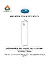
5.4 Functional elements: System boiler
14
1110
9
7
8
6
4
5
3
2
1
1617
13
15
12
1 Electronics box
2 Pressure relief valve for
the heating circuit
3 Condensate siphon
4 Flue pipe
5 Pressure sensor
6 Flue gas analysis point
(for the rear air/flue
connection)
7 Ignition transformer
8 Gas valve assembly
9 Air intake pipe
10 Fan/gas-air mixture
11 Supply air test point
(for the upper air/flue
connection)
12 Flue gas analysis point
(for the upper air/flue
connection)
13 Primary heat exchanger
14 Heating expansion
vessel
15 Purging hose
16 Heating pump
17 Bypass
5.5 Safety Devices
5.5.1 Electrical Supply Failure
The boiler will not work without an electrical supply. Normal
operation of the boiler should resume when the electrical
supply is restored.
Reset any external controls, to resume normal operation of
the central heating.
If the boiler does not resume normal operation press the
reset button. If the boiler does not resume normal operation
after this call your Installation/Servicing company or Vaillant
service.
5.5.2 Overheating Safety
The boiler software is designed to recognise the potential for
an overheat lockout and will shutdown before this happens.
To restart the boiler, press the reset button on the boiler
interface.
If the boiler fails to resume normal operation and all external
controls are calling for heat, then call your Installation/ Servi-
cing company or Vaillant service.
5.5.3 Frost protection
The appliance has a built in frost protection device that pro-
tects the boiler from freezing. With the gas and electric sup-
plies ON and irrespective of any room thermostat setting, the
frost protection device will operate the pump when the tem-
perature of the boiler water falls below 12 °C.
A timer is used so that the temperature can be checked peri-
odically. After 10 minutes the pump will be stopped if the
temperature is higher than 10 °C or has already reached
35 °C. The burner will activate if the boiler temperature does
not reach 10 °C after 30 minutes or at any time if the temper-
ature drops to 5 °C.
The burner will switch off when the temperature reaches
35 °C.
5.5.4 Condensate Drain Blockage
As a safety feature the boiler will stop working if the con-
densate drain becomes blocked. During freezing conditions
this may be due to the forming of ice in the condense drain
external to the house. Release an ice blockage by the use
of warm cloths on the pipe. After pressing reset the boiler
should restart.

0020230533_07 ecoFIT pure Installation and maintenance instructions 13
6 Set-up
6.1 Checking the scope of delivery
▶ Check that the scope of delivery is complete and intact.
Number Designation
1 Heat generator
1 Unit mounting bracket
1
Flexible condensate discharge pipe
4 3/4" seals
3 1/2" seals
2 Service valve
1 Gas stopcock
2 Connection pipe (heating flow and return)
1 Gas pipe
1 Drain pipe for the Pressure relief valve
1 Mounting template
1 Enclosed documentation
6.2 Dimensions
96
121
34
123
185
390
123
220
700
150
295
150
76
1 2 3
5
4
1 Heating flow
2 Gas connection
3 Heating return
4 Rear air/flue pipe con-
nection
5 Top air/flue pipe con-
nection

14 Installation and maintenance instructions ecoFIT pure 0020230533_07
6.3 Installation site
This boiler is not suitable for outdoor installation. This boiler
may be installed in any room. However if the boiler is being
installed in a room containing a bath or shower it must only
be installed in zones 2 or 3. In GB this is the current I.E.E.
WIRING REGULATIONS and BUILDING REGULATIONS. In
IE reference should be made to the current edition of I.S.813
“Domestic Gas Installations” and the current ETCI rules.
If the boiler is to be installed in a timber frame building it
should be fitted in accordance with the current version of the
Institute of Gas Engineers document IGE/UP/7. If in doubt
seek advice from local gas undertaking or the manufacturer.
6.4 Minimum clearances
CC
A
B
D
Minimum clearance
A 150 mm (top air/flue connection)
20 mm (rear air/flue connection)
B 150 mm
C 5 mm
(70 mm, if the side sections have to be removed)
D 500 mm
The boiler and flue are suitable for installation onto and
through combustible materials provided that:
1. Minimum 5 mm clearance is maintained around the
circumference of the flue (air intake).
2. The combustible surface and fixings are suitable for
supporting the load.
3. The minimum clearances from the boiler case are main-
tained.
6.5 Compartment Ventilation
The boilers are very high efficiency appliances.
As a consequence the heat loss from the appliance casing
during operation is very low.
Compartment ventilation is not required as the products are
only certified, and can only be fitted with a concentric flue
system.
6.6 Air/flue pipe
6.6.1 Regulation
Different flue outlet configurations can be carried out.
– Consult the installation manual for air/flue gas systems
for more information about the other possibilities and
associated accessories.
Minimum fall
44 mm/m
– Standard flue terminal kits have an in-built fall back to
the boiler to drain the condensate. These can be fitted
level between the appliance and the termination position.
All other extended flues must have a fall of at least 44
mm/m.
The maximum length of the flue outlet is defined according to
its type (for example C13).
– Whatever the kind of flue system chosen, observe the
minimum distances to position the flue terminals.
– To install the flue, refer to the separate flue instruction
supplied with your appliance.
– Explain these requirements to the user of the appliance.
In GB the minimum acceptable siting dimensions for the
terminal from obstructions, other terminals and ventilation
openings are shown in diagram overleaf.
In IE the minimum distances for flue terminal positioning
must be those detailed in I.S. 813 “Domestic Gas Installa-
tions”.
The terminal must be exposed to the external air, allowing
free passage of air across it at all times.
Being a condensing boiler some pluming may occur from
the flue outlet. This should be taken into consideration when
selecting the position for the terminal.

0020230533_07 ecoFIT pure Installation and maintenance instructions 15
6.6.2 Position of the air/flue terminal
J
J
N
Q
S
S
P
U
B
Boundary
G
D
J
J
R
V
M
T
G
C
W
E
F
L
A
K
S
P
S
F
X
A
Y
Boundary
Z
H
Aa
S
Z
Ba
6.6.2.1 Positioning the terminal of a fan-supported flue system
Installation site Dimensions
A
Adjacent to a boundary. 300 mm
B
1)
The dimension below eaves, balconies and car ports can be reduced to this value, as long as the flue terminal is
extended to clear any overhang. External flue joints must be sealed with a suitable silicon sealant.
25 mm
C Between a vertical flue terminal and a window or dormer window on a roof. 1,500 mm
D Between terminals facing each other. 1,200 mm
E Vertical flue clearance, adjacent to a boundary line. 300 mm
F
2)
Distance to a boundary line, unless it will cause a nuisance. BS 5440:Part 1 recommends that care is taken
when siting terminal in relation to boundary lines.
600 mm
G Minimum clearance from a skylight to a vertical flue or to another vertical flue. Min. 300 mm
H
Vertical flue clearance, to noncombustible building material.
Vertical flue clearance to combustible building material.
500 mm
1,500 mm
J Above, below and either side of an opening door, air vent or opening window. 300 mm
K Diagonally to an opening door, air vent or opening window. 600 mm
L
2)
To an internal or external corner. 200 mm
M
Below a Velux window.
Above or to either side of the Velux window.
2,000 mm
600 mm
N
From a pitched roof.
In regions with heavy snowfall.
400 mm
500 mm
P From vertical drain pipes and soil pipes. 25 mm
Q
Below eaves.
Below gutters, pipe and drains.
200 mm
75 mm
1) There should be no ventilation/opening in the eaves within 300 mm distance of the terminal.
2) These dimensions comply with the building regulations, but they may need to be increased to avoid wall
staining and nuisance from pluming depending on site conditions.
– Terminals must be positioned so to avoid combustion products entering the building.
– Support the flue at approximately one metre intervals and at a change of direction, use suitable brackets and
fixings.
– Installations in car ports are not recommended.
– The flue cannot be lower than 1 metre from the top of a lightwell due to the build up of combustion products.
– Dimensions from a flue terminal to a fanned air inlet to be determined by the ventilation equipment.

16 Installation and maintenance instructions ecoFIT pure 0020230533_07
Installation site Dimensions
R
The dimension below eaves, balconies and car ports can be reduced to this value, as long as the flue terminal is
extended to clear any overhang. External flue joints must be sealed with suitable silicon sealant.
25 mm
S Above adjacent ground or balcony. 300 mm
T
2)
Distance to a surface facing a terminal, unless it will cause a nuisance. BS 5440: Part 1 recommends that care
is taken when siting terminals in relation to surfaces facing a terminal.
600 mm
U Clearance alongside another terminal. 300 mm
V Above roof level. 300 mm
W Minimum to vertical structure on roof, roof vent. Min. 300 mm
X Minimum to opening in adjacent building. Min.
2000 mm
Y Minimum at an angle to a boundary which is not less than 300 mm to the terminal Min. 600 mm
Z Minimum measured to the nearest corner of the OPEN window Min. 600 mm
Aa No more than this value above ridge. Max.
300 mm
Ba Not less than this value below the opening window Min. 300 mm
1) There should be no ventilation/opening in the eaves within 300 mm distance of the terminal.
2) These dimensions comply with the building regulations, but they may need to be increased to avoid wall
staining and nuisance from pluming depending on site conditions.
– Terminals must be positioned so to avoid combustion products entering the building.
– Support the flue at approximately one metre intervals and at a change of direction, use suitable brackets and
fixings.
– Installations in car ports are not recommended.
– The flue cannot be lower than 1 metre from the top of a lightwell due to the build up of combustion products.
– Dimensions from a flue terminal to a fanned air inlet to be determined by the ventilation equipment.
6.6.2.2 Horizontal terminal positioning
BS 5440-1 recommends that fanned flue chimney terminals should be positioned as follows:
a) at least 2 m from an opening in the building directly opposite, and
b) so that the products of combustion are not directed to discharge directly across a boundary if the products are likely to
cause a nuisance to a neighbour or discharge over a walkway or patio.
For IE see current issue of IS 813.
For boilers covered within this manual.
Dimensions B and R:
These clearances may be reduced to 25 mm without affecting the performance of the boiler. In order to ensure that the con-
densate plume does not affect adjacent surfaces the terminal should be extended as shown below.
Balcony/eaves
Gutter
Adequately secured
air/flue gas pipe
The flue pipe must
protrude beyond any overhang
You can use a plume management kit to enable the termination point to be positioned and directed away from the building
fabric.

0020230533_07 ecoFIT pure Installation and maintenance instructions 17
6.6.3 Flue Configuration Description
6.6.3.1 Horizontal Concentric Flue ⌀ 60/100 mm or
⌀ 80/125 mm (C13 type installation)
1
1 Gasket (fitted)
Note
If the terminal is at less than 1.80 m from the
ground, you must install a terminal protection kit.
Consult the separate installation manual for air/flue gas sys-
tems supplied with your appliance for all possibilities and as-
sociated accessories and how to install the flue system.
6.6.3.2 Terminal protection
A terminal guard is required if persons could come into con-
tact with the terminal or the terminal could be subject to dam-
age.
If a terminal guard is required, it must be positioned to
provide minimum of 50 mm clearance from any part of the
terminal and be central over the terminal.
The guard should be similar to that shown in the figure.
6.6.3.3 Vertical Concentric Flue ⌀ 60/100 mm or
⌀ 80/125 mm (C33 type installation)
Consult the separate installation manual for air/flue gas sys-
tems supplied with your appliance for all possibilities and as-
sociated accessories and how to install the flue system.
6.7 Using the mounting template
▶ Use the mounting template to ascertain the locations at
which you need to drill holes.
6.8 Wall-mounting the product
Note
If you are using the rear air/flue connection, in-
stall the air/flue pipe before you wall-mount the
product.
1. Check the load-bearing capacity of the wall.
2. Note the total weight of the product.
3. Only use fixing material that is permitted for the wall.
4. If required, ensure that mounting apparatus on-site has
sufficient load-bearing capacity.
5. Wall-mount the product as described.

18 Installation and maintenance instructions ecoFIT pure 0020230533_07
6.9 Removing/installing the front casing
6.9.1 Front casing, removing
B
C
A
6.9.2 Installing the front casing
▶ Refit the components in the reverse order.
6.10 Removing/installing the side section
6.10.1 Removing the side section
Caution.
Risk of material damage caused by mech-
anical deformation.
Removing both side sections may cause
mechanical distortion in the product, which
may cause damage to the piping, for ex-
ample, and potentially result in leaks.
▶ Always only remove one side section –
never both side sections at the same time.
Note
If there is sufficient lateral clearance (at least
70 mm), you can remove the side section to fa-
cilitate maintenance or repair work.
2x
A
B
C
D
6.10.2 Installing the side section
▶ Refit the components in the reverse order.

0020230533_07 ecoFIT pure Installation and maintenance instructions 19
7 Installation
7.1 Preparing for installation
▶ Make sure that the existing gas meter is capable of
passing the rate of gas supply required.
▶ Consider the maximum heat output given in DHW mode.
▶ Install the following components:
– Draining cocks at the lowest points in the heating
installation (→ current version of "BS 2879")
– A stopcock in the gas pipe
▶ Check that the volumetric capacity of the expansion ves-
sel is sufficient for the system volume.
▽ If the volume of the expansion vessel is insufficient
for the installation.
▶ Install an additional expansion vessel in the heat-
ing return, as close to the product as possible.
▶ Install a non-return flap at the product's outlet
(heating flow).
▶ Install the connection pipes such that they are free from
mechanical stress.
▶ If you use non-diffusion-tight plastic pipes in the heating
installation, ensure that no air gets into the heat gener-
ator circuit.
▶ Only solder connectors if the connectors are not yet
screwed to the service valves.
▶ Only bend connection pipes if they have not yet been
connected to the product.
▶ Flush the heating installation thoroughly before installing
the product.
▶ Check the leak-tightness of the gas valve assembly using
a pressure of ≤ 11 kPa (110 mbar).
7.2 Descaling the water
Scale deposition increases as the water temperature in-
creases.
▶ Descale the water as required.
7.3 Check compliance with the local gas group
The product's combustion has been factory tested and is
preset for operation with the gas group indicated on the data
plate.
The product is only authorised to be operated with natural
gas.
▶ Check the information about the gas type indicated on
the data plate and compare this with the gas type avail-
able at the installation site.
Condition: The product design is not compatible with the local gas group
▶ Do not start up the product.
Condition: The product design is compatible with the local gas group
▶ Proceed as described below.
7.4 Gas and water connections
1
2
3
4
5
1 Heating flow connec-
tion, G3/4
2 Flow connection to the
domestic hot water
cylinder, G3/4
3 Gas connection, G1/2
4 Return connection to
the domestic hot water
cylinder, G3/4
5 Heating return connec-
tion, G3/4
1. Connect the water and gas connections in accordance
with the applicable standards.
2. Purge the gas pipe before start-up.
3. Check the entire gas pipe properly for leak-tightness.
7.5 Connecting the drain pipework for the
expansion relief valve
1
▶ Ensure that the pipeline is visible.
▶ The pipe must have a continuous fall and be routed to a
position so that any discharge of water, possibly boiling,
or steam cannot create any danger to persons, damage
to property or external electrical components and wiring.
◁ The piping must be installed in such a way that you
can see when water drips out.

20 Installation and maintenance instructions ecoFIT pure 0020230533_07
7.6 Connecting the condensate discharge pipe
1
2
▶ Follow the instructions listed here and observe the legal
and local regulations on condensate discharge.
▶ Use PVC or any other material that is suitable for drain-
ing the non-neutralised condensate.
▶ If you cannot guarantee that the materials from which the
drain pipework is made are suitable, install a system for
neutralising the condensate.
Note
The condensate drain pipework must have a
continuous fall (45 mm per metre) and should
whenever possible terminate at a suitable
drain point within the heated envelope of the
building that will remain frost free under long
periods of low external temperatures.
▶ Connect the condensate traps (1). Use the supplied drain
hose (2) for this.
Note
Ensure that the connection between the con-
densate discharge pipe and the drain hose is
not air-tight.
▶ Connect a condensate discharge pipe (21.5 mm, not
included in the scope of delivery) to the drain hose (2).
▶ During installation remove all burrs from inside of cut pipe
work and avoid excessive adhesive which may trap small
pockets of water close to the pipe wall which can freeze
and build into a larger ice plug.
▶ For any installation the condensate must be free flowing
and not be possible for air back-pressure to prevent wa-
ter flow.
▶ As with other pipe work insulate the condensate dis-
charge pipe to minimise any risk of freezing and beware
when crossing cavities that the fall is maintained and the
pipe sleeved.
You can find further information in specification "BS 6798"
for installing and maintaining gas-fired boilers with a nominal
heat input below 70 kW.
7.6.1 Condensate discharge systems
It is not necessary to provide extra traps in the discharge
pipe as there is already a trap inside the boiler. Fitting an
extra trap may cause the boiler siphon to work incorrectly.
Refer to BS5546 or BS6798 for further advice on disposal of
boiler condensate.
7.6.1.1 Direct Connection to internal soil and vent
stack
Ø22mm
Preferred option
7.6.1.2 Direct connection to external soil and vent
stack
Ø22mm
Ø 32mm
≤ 3 m
7.6.1.3 External termination to gulley or hopper
Ø22mm
Ø 32mm
≤ 3 m
Best practice
7.6.1.4 Internal termination into combined sink
waste
Ø32mm
Ø22mm
≥ 3 m
100mm
/