Page is loading ...

Installation and main-
tenance instructions
MicraCom
24c-AS/1
28c-AS/1
GB, IE

Contents
2 Installation and maintenance instructions MicraCom 0020289288_02
Contents
1 Safety .................................................................... 3
1.1 Intended use.......................................................... 3
1.2 Qualification........................................................... 3
1.3 General safety information .................................... 3
1.4 Regulations (directives, laws, standards) .............. 5
1.5 List of relevant standards for Great Britain and
Ireland.................................................................... 5
2 Guarantee and Customer Service...................... 6
3 Technical data...................................................... 7
4 Notes on the documentation .............................. 9
5 Product description............................................. 9
5.1 Product design....................................................... 9
5.2 Safety Devices....................................................... 9
5.3 Data plate ............................................................ 10
5.4 Serial number ...................................................... 10
5.5 CE marking.......................................................... 10
6 Set-up.................................................................. 10
6.1 Checking the scope of delivery............................ 10
6.2 Product dimensions ............................................. 10
6.3 Installation site..................................................... 11
6.4 Minimum clearances............................................ 11
6.5 Air/flue pipe.......................................................... 11
6.6 Using the mounting template............................... 17
6.7 Wall-mounting the product................................... 17
7 Installation.......................................................... 17
7.1 Requirements ...................................................... 18
7.2 Flushing the heating installation for the first
time ("cold") ......................................................... 18
7.3 Connecting gas and water................................... 19
7.4 Connecting the condensate discharge hose ....... 19
7.5 Condensate discharge systems .......................... 19
7.6 Connecting the drain pipework for the
expansion relief valve .......................................... 21
7.7 Filling the condensate siphon .............................. 21
7.8 Air/flue system ..................................................... 21
7.9 Electrical installation ............................................ 21
8 Operation............................................................ 23
8.1 Calling up the installer level................................. 23
8.2 Using diagnostics codes...................................... 24
8.3 Running check programmes................................ 24
8.4 Calling up status codes........................................ 24
8.5 Exiting the installer level ...................................... 24
9 Start-up ............................................................... 24
9.1 Carrying out the initial start-up............................. 24
9.2 Checking and treating the heating water/filling
and supplementary water .................................... 24
9.3 Filling the heating installation .............................. 25
9.4 Purging the heating installation ........................... 26
9.5 Filling and purging the domestic hot water
system ................................................................. 26
9.6 Check and gas setting ......................................... 26
9.7 Checking the heating mode................................. 29
9.8 Checking the domestic hot water generation ...... 29
9.9 Checking leak-tightness ...................................... 29
9.10 Thoroughly flushing the heating installation
("hot")................................................................... 29
10 Adapting the unit to the installation ................ 29
10.1 Adapting the heating settings .............................. 29
11 Handing over to the end user........................... 30
12 Inspection and maintenance ............................ 31
12.1 Checking and setting the CO₂ content................. 31
12.2 Moving the expansion vessel to the
maintenance position on the combustion
block .................................................................... 32
12.3 Moving the expansion vessel to the
maintenance position on the hydraulic block....... 32
12.4 Cleaning/checking the components..................... 32
12.5 Draining the product ............................................ 37
12.6 Completing inspection and maintenance work .... 37
13 Troubleshooting ................................................ 37
13.1 Querying the fault memory .................................. 37
13.2 Eliminating faults.................................................. 37
13.3 Resetting parameters to factory settings ............. 37
13.4 Replacing defective components......................... 37
14 Decommissioning.............................................. 39
14.1 Temporary decommissioning .............................. 39
14.2 Permanently decommissioning............................ 39
15 Recycling and disposal..................................... 39
16 Customer service............................................... 39
Appendix ............................................................................ 40
A Inspection and maintenance work................... 40
B Diagnostics codes............................................. 40
C Status codes ...................................................... 43
D Fault codes......................................................... 44
E Check programmes ........................................... 48
F Wiring diagram................................................... 49
G Commissioning Checklist................................. 50
Index ................................................................................... 54

Safety 1
0020289288_02 MicraCom Installation and maintenance instructions 3
1 Safety
1.1 Intended use
The product is intended as a heat generator
for sealed heating installations and for do-
mestic hot water generation.
Improper use of any kind is prohibited.
Intended use also includes the following:
– Installing and operating the product only
in conjunction with accessories for the
air/flue pipe which are listed in the other
applicable documents and comply with the
type of unit
– Using the product while observing the ac-
companying operating, installation and
maintenance instructions for the product
along with all other components of the in-
stallation
– Installing and setting up the product while
observing the product and system ap-
proval
– Observing all inspection and maintenance
conditions listed in the instructions
– Installing while observing the IP code
The following is classed as improper use:
– Using the product in vehicles, such as mo-
bile homes or caravans. Units that are not
classed as vehicles are those that are in-
stalled in a fixed and permanent location
(known as "fixed installation").
– Any direct use in industrial or commercial
processes
– Any use other than those described in
these instructions and any use that goes
beyond what is described here
1.2 Qualification
The person carrying out the work described
here must have completed professional train-
ing. The competent person must demon-
strably have all of the knowledge, skills and
capabilities that are required in order to carry
out the work mentioned below.
The following work must only be carried out
by competent persons who are sufficiently
qualified to do so:
– Set-up
– Dismantling
– Installation
– Start-up
– Inspection and maintenance
– Repair
– Decommissioning
▶ Proceed in accordance with current tech-
nology.
▶ Use the correct tool.
The above-mentioned work must always only
be carried out by persons with sufficient qual-
ifications.
This product can be used by children over
eight years old and also by persons with lim-
ited physical, sensory or mental capabilities
or insufficient experience and/or knowledge if
they are supervised or have been provided
with instructions on how to safely use the
product, and they understand the risks res-
ulting from using the product. Children must
not play with the product. Cleaning and user
maintenance work must not be carried out by
children unless they are supervised.
1.3 General safety information
The following sections convey important
safety information. It is essential to read and
observe this information in order to prevent
risk of death, risk of injury, material damage
or environmental damage.
1.3.1 Risk of death from escaping gas
What to do if you smell gas in the building:
▶ Avoid rooms that smell of gas.
▶ If possible, open doors and windows fully
and ensure adequate ventilation.
▶ Do not use naked flames (e.g. lighters,
matches).
▶ Do not smoke.
▶ Do not use any electrical switches, mains
plugs, doorbells, telephones or other com-
munication systems in the building.
▶ If it is safe to do so, close the emergency
control valve or the main isolator.
▶ If possible, close the gas stopcock on the
product.
▶ Warn other occupants in the building by
yelling or banging on doors or walls.
▶ Leave the building immediately and ensure
that others do not enter the building.

1 Safety
4 Installation and maintenance instructions MicraCom 0020289288_02
▶ Notify the gas supply company or
the Emergency Service Provider
+44 (0) 800 111999 by telephone once you
are outside of the building.
1.3.2 Flue gas
Flue gases may cause poisoning, while hot
flue gases may also cause burns. Flue gases
must therefore never be allowed to escape
uncontrollably.
What to do if you smell flue gas in the prop-
erty:
▶ Open all accessible doors and windows
fully to provide ventilation.
▶ Decommission the product.
▶ Check the flue gas routes in the product
and the flue gas diversions.
To prevent flue gas exit:
▶ Only operate the product if the air/flue pipe
has been completely installed.
▶ With the exception of short periods for
testing purposes, only operate the product
when the front casing is installed and
closed.
▶ In order to operate the product, ensure that
the condensate siphon is always full.
– Water seal level for B23 or B23P unit
types with condensate siphon (third-
party accessory): ≥ 200 mm
To ensure that the seals are not damaged:
▶ Instead of grease, use only water or com-
mercially available soft soap to aid installa-
tion.
1.3.3 Air supply
Unsuitable or insufficient combustion and
room air may lead to material damage, but
also to life-threatening situations.
To ensure that the combustion air supply is
sufficient during open-flued operation:
▶ Ensure that the air supply to the product's
installation room is permanently unobstruc-
ted and sufficient in accordance with the
relevant ventilation requirements. This also
applies, in particular, for cupboard installa-
tions.
To prevent corrosion on the product and in
the flue system:
▶ Ensure that the combustion air supply is
free from sprays, solvents, chlorinated
cleaning agents, paint, adhesives, am-
monia compounds, dust or similar sub-
stances.
▶ Ensure that no chemical substances are
stored at the installation site.
▶ If you are installing the product in
hairdressing salons, painter's or joiner's
workshops, cleaning businesses or similar
locations, choose a separate installation
room in which the room air is technically
free of chemical substances.
1.3.4 Electricity
The power supply terminals L and N remain
live.
To prevent electric shocks, proceed as fol-
lows before working on the product:
▶ Disconnect the product from the power
supply by switching off all power supplies
at all poles (electrical partition with a con-
tact gap of at least 3 mm, e.g. fuse or cir-
cuit breaker) or remove the mains plug (if
present).
▶ Secure against being switched back on
again.
▶ Wait at least three minutes until the con-
densers have discharged.
▶ Check that there is no voltage.
1.3.5 Weight
To prevent injuries when transporting the
product:
▶ Make sure that the product is transported
by at least two people.
1.3.6 Explosive and flammable substances
To prevent explosions and fire:
▶ Do not use the product in storage rooms
that contain explosive or flammable sub-
stances (such as petrol, paper or paint).
1.3.7 High temperatures
To prevent burns:
▶ Only carry out work on components once
they have cooled down.
To prevent material damage that is caused
by heat transfer:

Safety 1
0020289288_02 MicraCom Installation and maintenance instructions 5
▶ Only solder connectors if the connectors
are not yet screwed to the service valves.
1.3.8 Heating water
Both unsuitable heating water and air in the
heating water may cause material damage to
the product and in the heat generator circuit.
▶ Check the quality of the heating water.
(→ Page 24)
▶ If you use non-diffusion-tight plastic pipes
in the heating installation, ensure that no
air gets into the heat generator circuit.
1.3.9 Neutralisation device
To prevent contamination of the waste water:
▶ Check whether a neutralising unit must
be installed in accordance with national
regulations.
▶ Observe local regulations on neutralising
condensate.
1.3.10 Frost
To prevent material damage:
▶ Do not install the product in rooms prone
to frost.
1.3.11 Safety devices
▶ Install the necessary safety devices in the
installation.
1.4 Regulations (directives, laws,
standards)
▶ Observe the national regulations, stand-
ards, directives, ordinances and laws.
1.5 List of relevant standards for Great
Britain and Ireland
▶ You can find a list of relevant standards at
https://www.glow-worm.co.uk/standards.

2 Guarantee and Customer Service
6 Installation and maintenance instructions MicraCom 0020289288_02
2 Guarantee and Customer Service
Guarantee Registration
Thank you for installing a new Glow-worm appliance in your home.
Glow-worm appliances are manufactured to the very highest standard so we are pleased to offer
our customers a comprehensive guarantee.
To maintain your guarantee, the boiler must be serviced annually by a competent person who
holds the required qualifications in accordance with the rules in force of the country where the
product is installed and in accordance with the manufactures recommendations.
We recommend you complete your guarantee registration as soon as possible.
Sales Support:
Telephone: 0345 602 0262
Technical Enquiries:
Telephone: 01773 828300
Email: [email protected]
General Enquiries:
Telephone: 01773 828100
Training Enquiries:
Telephone: 0345 601 8885
Email: [email protected]
Spares Enquiries:
Telephone: 01773 881383
To register your Glow-worm appliance visit:
Glow-worm is a licensed member of the Benchmark Scheme. Benchmark places responsibilities on both manufacturers and
installers. The purpose is to ensure that customers are provided with the correct equipment for their needs, that it is installed,
commissioned and serviced in accordance with the manufacturer’s instructions by a competent person approved at the time
by the Health and Safety Executive and that it meets the requirements of the appropriate Building Regulations.
The Benchmark Checklist can be used to demonstrate compliance with Building Regulations and should be provided to the
customer for future reference.
Installers are required to carry out installation, commissioning and servicing work in accordance with the Benchmark Code of
Practice which is available from the Heating and Hotwater Industry Council who manage and promote the Scheme.
Benchmark is managed and promoted by the Heating and Hotwater Industry Council.
https://self-service.glow-worm.co.uk/warranty-registration

Technical data 3
0020289288_02 MicraCom Installation and maintenance instructions 7
3 Technical data
Technical data – General
24c-AS/1 28c-AS/1
Designated country (designation in accordance with ISO 3166)
GB, IE GB, IE
Permissible gas categories
ll2H3P ll2H3P
CE number
0063CU3005 0063CU3005
ErP
92 % 93 %
Product-side gas connection
1/2" 1/2"
Product-side flow/return heating connections
3/4" 3/4"
Expansion relief valve connection pipe (min.)
15 mm 15 mm
Condensate discharge hose (min.)
14.2 mm 14.2 mm
Gas connection pressure, G20 natural gas
2.0 kPa
(20.0 mbar)
2.0 kPa
(20.0 mbar)
Gas connection pressure, liquefied petroleum gas G31
3.7 kPa
(37.0 mbar)
3.7 kPa
(37.0 mbar)
Maximum flue gas temperature
89 ℃ 89 ℃
Min. gas volume flow at 15 °C and 1013 mbar, G20
0.66 m³/h 0.76 m³/h
Min. gas volume flow at 15 °C and 1013 mbar, G31
0.65 kg/h 0.56 kg/h
Max. gas volume flow at 15 °C and 1013 mbar (based on heating mode), G20
1.99 m³/h 2.59 m³/h
Max. gas volume flow at 15 °C and 1013 mbar (based on heating mode), G31
1.47 kg/h 1.91 kg/h
Max. gas volume flow at 15 °C and 1013 mbar (based on domestic hot water
generation), G20
2.54 m³/h 2.96 m³/h
Max. gas volume flow at 15 °C and 1013 mbar (based on domestic hot water
generation), G31
1.86 kg/h 2.18 kg/h
Permissible installation types
C13, C33, C43, C53 C13, C33, C43, C53
Nominal efficiency in partial load mode (30%)
107.8 % 108.2 %
NOx class
6 6
Nitrogen oxide emissions, NOx weighted (Hs) (G20)
27.11 mg/kW⋅h 32.40 mg/kW⋅h
CO emissions
137.2 ppm 121.7 ppm
Net weight
25.6 kg 26.5 kg
Technical data – Power/load (G20)
24c-AS/1 28c-AS/1
Nominal heat output range P at 50/30 °C
6.6 to 20.0 kW 7.7 to 25.9 kW
Nominal heat output range P at 60/40 °C
6.4 to 19.3 kW 7.5 to 25.1 kW
Nominal heat output range P at 75/55 °C
6.0 to 18.3 kW 6.9 to 23.9 kW
Max. heat input for domestic hot water (Qmax) (Hi)
24.0 kW 28.0 kW
Flue gas mass flow rate in heating mode at P min.
3.2 g/s 3.7 g/s
Flue gas mass flow rate in heating mode at P max.
8.9 g/s 11.6 g/s
Nominal heat input range for heating
6.2 to 18.8 kW 7.2 to 24.5 kW
Technical data – Power/load (G31)
24c-AS/1 28c-AS/1
Nominal heat output range P at 50/30 °C
9.0 to 20.0 kW 7.7 to 25.9 kW
Nominal heat output range P at 75/55 °C
8.1 to 18.3 kW 6.9 to 23.9 kW
Max. heat input for domestic hot water (Qmax)
24.0 kW 28.0 kW
Flue gas mass flow rate in heating mode at P min.
4.0 g/s 3.4 g/s
Flue gas mass flow rate in heating mode at P max.
9.1 g/s 11.8 g/s
Nominal heat input range for heating
8.4 to 18.8 kW 7.2 to 24.5 kW

3 Technical data
8 Installation and maintenance instructions MicraCom 0020289288_02
Technical data – Heating
24c-AS/1 28c-AS/1
Maximum heating flow temperature (factory setting – D.71)
75 ℃ 75 ℃
Maximum flow temperature adjustment range
30 to 75 ℃ 30 to 75 ℃
Maximum operating pressure (MWP)
0.3 MPa
(3.0 bar)
0.3 MPa
(3.0 bar)
Nominal water flow (ΔT = 20 K)
788 l/h 1,029 l/h
Approximate value for the condensate volume during nominal load operation
(pH value between 3.5 and 4.0) at 50/30 °C
1.89 l/h 2.46 l/h
Remaining pump head (at nominal circulation water volume)
0.027 MPa
(0.270 bar)
0.017 MPa
(0.170 bar)
Contents of the heating expansion vessel
8 l 8 l
Technical data – Domestic hot water
24c-AS/1 28c-AS/1
Minimum water flow
1.7 l/min 1.7 l/min
Specific flow rate D (ΔT = 30 K)
11.5 l/min 13.4 l/min
Specific flow rate D (ΔT = 35 K)
9.9 l/min 11.5 l/min
Permissible operating pressure
0.03 to 1 MPa
(0.30 to 10 bar)
0.03 to 1 MPa
(0.30 to 10 bar)
Recommended supply pressure
0.3 MPa
(3.0 bar)
0.3 MPa
(3.0 bar)
Hot water comfort in accordance with the standard EN 13203
** **
Flow rate limiter for cold water
8.0 l/min 10.0 l/min
Domestic hot water output temperature range
35 to 55 ℃ 35 to 55 ℃
Technical data – Electrics
24c-AS/1 28c-AS/1
Electrical connection
230 V/50 Hz 230 V/50 Hz
Permissible connected voltage
195 to 253 V 195 to 253 V
Built-in fuse (slow-blow)
T2/2 A, 250 V T2/2 A, 250 V
Maximum electrical power consumption
90 W 90 W
Standby electrical power consumption
1.7 W 1.7 W
IP rating
IPX5 IPX5

Notes on the documentation 4
0020289288_02 MicraCom Installation and maintenance instructions 9
4 Notes on the documentation
▶ Always observe all the operating and installation instruc-
tions included with the system components.
▶ Pass these instructions and all other applicable docu-
ments on to the end user.
These instructions apply only to:
Product article number
Article num-
ber
Gas Council
Number
MicraCom 24c-AS/1 (H-GB)
0010026136 47-019-58
MicraCom 28c-AS/1 (H-GB)
0010026137 47-019-59
5 Product description
This product is a gas-fired wall-hung condensing boiler.
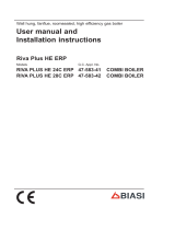
5.1 Product design
2
1
3
4
12
13
16
14
15
17
11
7
5
6
7
8
9
10
1 Electronics box
2 Expansion relief valve
for heating
3 Condensate siphon
4 Pump
5 Gas valve assembly
6 Ignition and flame con-
trol electrode
7 Restrictor for the refer-
ence pressure pipe
8 Burner
9 Venturi
10 Heat exchanger
11 Reference pressure
pipe for the gas valve
assembly
12 Fan
13 Expansion vessel
14 Domestic hot water
plate heat exchanger
15 Domestic hot water
volume flow sensor
16 Pressure sensor
17 Prioritising diverter
valve
5.2 Safety Devices
5.2.1 Electrical Supply Failure
The boiler will not work without an electrical supply. Normal
operation of the boiler should resume when the electrical
supply is restored.
Reset any external controls, to resume normal operation of
the central heating.
If the boiler does not resume normal operation reset the
boiler. If the boiler does not resume normal operation after
this call your Installation/Servicing company or Glow worm
service.
5.2.2 Overheating Safety
The boiler software is designed to recognise the potential for
an overheat lockout and will shutdown before this happens.
To restart the boiler, press the button more than 3s.
If the boiler fails to resume normal operation and all external
controls are calling for heat, then call your Installation/ Servi-
cing company or Glow worm service.
5.2.3 Frost protection
The appliance has a built in frost protection device that pro-
tects the boiler from freezing. With the gas and electric sup-
plies ON and irrespective of any room thermostat setting, the
frost protection device will operate the pump when the tem-
perature of the boiler water falls below 8°C.
A timer is used so that the temperature can be checked peri-
odically. After 10 minutes the pump will be stopped if the
temperature is higher than 10°C or has already reached
35°C. The burner will activate if the boiler temperature does
not reach 10°C after 30 minutes or at any time if the temper-
ature drops to 5°C.
The burner will switch off when the temperature reaches
35°C.
5.2.4 Condensate Drain Blockage
During freezing conditions the condensate drain can become
blocked, this may be due to the forming of ice in the con-
dense drain external to the house. Release an ice blockage
by the use of warm cloths on the pipe.

6 Set-up
10 Installation and maintenance instructions MicraCom 0020289288_02
5.3 Data plate
The data plate is mounted on the rear of the electronics box
and on the upper side of the product at the factory. Any in-
formation that is not listed here can be found in separate
sections.
Information Meaning
Read the instructions.
... Condens ... Marketing name
ES, IT, etc. Target market
Cat. Approved gas category
Type Products of the category
2H, 2HS, 2ELw...
- G20, G31... -
XX mbar (X.X kPa)
Gas group and gas connection pressure
as set at the factory
T
max
Maximum flow temperature
PMS Permissible operating pressure, heating
mode
NOx class NOx class (nitrogen oxide emissions)
D Specific flow rate
V Mains voltage
Hz Mains frequency
W Maximum electrical power consumption
IP IP rating
Code (DSN) Product code
PMW Permissible operating pressure for do-
mestic hot water mode
Heating mode
Q
n
Heat input range
P
n
Nominal heat output range (75/55 °C)
P
nc
Condensing nominal heat output range
(50/30 °C)
DHW mode
P
nw
Maximum heat output in domestic hot
water generation mode
Q
nw
Maximum heat input in domestic hot
water generation mode
Hi Lower gross calorific value
Barcode with serial number
3rd to 6th digits = production date
(year/week)
7th to 16th digit = product article number
GC no. Gas council number
Note
Make absolutely sure that the product is compat-
ible with the gas group at the installation site.
5.4 Serial number
You can find the serial number on the data plate and on the
sticker on the upper side of the product.
The serial number and the product designation can also be
found on a sticker under the product's front casing.
5.5 CE marking
The CE marking shows that the products comply with the
basic requirements of the applicable directives as stated on
the declaration of conformity.
The declaration of conformity can be viewed at the manufac-
turer's site.
6 Set-up
6.1 Checking the scope of delivery
Quantity Designation
1
Gas-fired wall-hung boiler
1 Bag containing valves for gas, heating and domestic
hot water
1 Drain spigot of the expansion relief valve
2 Bag with small parts
1 Condensate discharge hose
1 Enclosed documentation
6.2 Product dimensions
130
270
400
626

Set-up 6
0020289288_02 MicraCom Installation and maintenance instructions 11
E-BUS
130
202
213
200
156
111
119
169
71.5
30.5
85
Ø15 3/4” 3/4” 3/4” 3/4”1/2”
29
6.3 Installation site
If the boiler is to be installed in a timber frame building it
should be fitted in accordance with the current version of the
Institute of Gas Engineers document IGE/UP/7. If in doubt
seek advice from local gas undertaking or the manufacturer.
6.4 Minimum clearances
C C
AB
D
Minimum clearance
A 60/100 mm diameter air/flue pipe: 150 mm
80/125 mm diameter air/flue pipe: 276 mm
B 180 mm
C 5 mm
D 500 mm
(This clearance can be reduced to 5 mm if the product is
installed behind a removable plate or a door)
The boiler and flue are suitable for installation onto and
through combustible materials provided that:
1. Minimum 5 mm clearance is maintained around the
circumference of the flue (air intake).
2. The combustible surface and fixings are suitable for
supporting the load.
3. The minimum clearances from the boiler case are main-
tained.
6.4.1 Compartment Ventilation
The boilers are very high efficiency appliances.
As a consequence the heat loss from the appliance casing
during operation is very low.
Compartment ventilation is not required as the products are
only certified, and can only be fitted with a concentric flue
system.
6.5 Air/flue pipe
6.5.1 Regulation
Different flue outlet configurations can be carried out.
– Consult the installation manual for air/flue gas systems
for more information about the other possibilities and
associated accessories.
Minimum fall
44 mm/m
– Standard flue terminal kits have an in-built fall back to
the boiler to drain the condensate. These can be fitted
level between the appliance and the termination position.
All other extended flues must have a fall of at least 44
mm/m.
The maximum length of the flue outlet is defined according to
its type (for example C13).
– Whatever the kind of flue system chosen, observe the
minimum distances to position the flue terminals.
– To install the flue, refer to the separate flue instruction
supplied with your appliance.
– Explain these requirements to the user of the appliance.
In GB the minimum acceptable siting dimensions for the
terminal from obstructions, other terminals and ventilation
openings are shown in diagram overleaf.
In IE the minimum distances for flue terminal positioning
must be those detailed in I.S. 813 “Domestic Gas Installa-
tions”.
The terminal must be exposed to the external air, allowing
free passage of air across it at all times.
Being a condensing boiler some pluming may occur from
the flue outlet. This should be taken into consideration when
selecting the position for the terminal.

6 Set-up
12 Installation and maintenance instructions MicraCom 0020289288_02
6.5.2 Terminal protection
A terminal guard is required if persons could come into con-
tact with the terminal or the terminal could be subject to dam-
age.
If a terminal guard is required, it must be positioned to
provide minimum of 50 mm clearance from any part of the
terminal and be central over the terminal.
The guard should be similar to that shown in the figure.

Set-up 6
0020289288_02 MicraCom Installation and maintenance instructions 13
6.5.3 Position of the air/flue terminal
J
J
N
Q
S
S
P
U
B
Boundary
G
D
J
J
R
V
M
T
G
C
W
E
F
L
A
K
S
P
S
F
X
A
Y
Boundary
Z
H
Aa
S
Z
Ba
6.5.3.1 Positioning the terminal of a fan-supported flue system
Installation site
Dimen-
sions
A
Adjacent to a boundary. 300 mm
B
1)
The dimension below eaves, balconies and car ports can be reduced to this value, as long as the flue terminal is
extended to clear any overhang. External flue joints must be sealed with a suitable silicon sealant.
25 mm
C Between a vertical flue terminal and a window or dormer window on a roof. 1,500 mm
D Between terminals facing each other. 1,200 mm
E Vertical flue clearance, adjacent to a boundary line. 300 mm
F
2)
Distance to a boundary line, unless it will cause a nuisance. BS 5440:Part 1 recommends that care is taken when
siting terminal in relation to boundary lines.
600 mm
G Minimum clearance from a skylight to a vertical flue or to another vertical flue.
Min.
300 mm
H
Vertical flue clearance, to noncombustible building material.
Vertical flue clearance to combustible building material.
500 mm
1,500 mm
J Above, below and either side of an opening door, air vent or opening window. 300 mm
K Diagonally to an opening door, air vent or opening window. 600 mm
L
2)
To an internal or external corner. 200 mm
M
Below a Velux window.
Above or to either side of the Velux window.
2,000 mm
600 mm
N
From a pitched roof.
In regions with heavy snowfall.
400 mm
500 mm
P From vertical drain pipes and soil pipes. 25 mm
1) There should be no ventilation/opening in the eaves within 300 mm distance of the terminal.
2) These dimensions comply with the building regulations, but they may need to be increased to avoid wall staining
and nuisance from pluming depending on site conditions.
– Terminals must be positioned so to avoid combustion products entering the building.
– Support the flue at approximately one metre intervals and at a change of direction, use suitable brackets and
fixings.
– Installations in car ports are not recommended.
– The flue cannot be lower than 1 metre from the top of a lightwell due to the build up of combustion products.
– Dimensions from a flue terminal to a fanned air inlet to be determined by the ventilation equipment.

6 Set-up
14 Installation and maintenance instructions MicraCom 0020289288_02
Installation site
Dimen-
sions
Q
Below eaves.
Below gutters, pipe and drains.
200 mm
75 mm
R
The dimension below eaves, balconies and car ports can be reduced to this value, as long as the flue terminal is
extended to clear any overhang. External flue joints must be sealed with suitable silicon sealant.
25 mm
S Above adjacent ground or balcony. 300 mm
T
2)
Distance to a surface facing a terminal, unless it will cause a nuisance. BS 5440: Part 1 recommends that care is
taken when siting terminals in relation to surfaces facing a terminal.
600 mm
U Clearance alongside another terminal. 300 mm
V Above roof level. 300 mm
W Minimum to vertical structure on roof, roof vent. Min.
300 mm
X Minimum to opening in adjacent building. Min.
2000 mm
Y Minimum at an angle to a boundary which is not less than 300 mm to the terminal Min.
600 mm
Z Minimum measured to the nearest corner of the OPEN window Min.
600 mm
Aa No more than this value above ridge. Max.
300 mm
Ba Not less than this value below the opening window Min.
300 mm
1) There should be no ventilation/opening in the eaves within 300 mm distance of the terminal.
2) These dimensions comply with the building regulations, but they may need to be increased to avoid wall staining
and nuisance from pluming depending on site conditions.
– Terminals must be positioned so to avoid combustion products entering the building.
– Support the flue at approximately one metre intervals and at a change of direction, use suitable brackets and
fixings.
– Installations in car ports are not recommended.
– The flue cannot be lower than 1 metre from the top of a lightwell due to the build up of combustion products.
– Dimensions from a flue terminal to a fanned air inlet to be determined by the ventilation equipment.
6.5.3.2 Horizontal terminal positioning
BS 5440-1 recommends that fanned flue chimney terminals should be positioned as follows:
a) at least 2 m from an opening in the building directly opposite, and
b) so that the products of combustion are not directed to discharge directly across a boundary if the products are likely to
cause a nuisance to a neighbour or discharge over a walkway or patio.
For IE see current issue of IS 813.
For boilers covered within this manual.
Dimensions B and R:
These clearances may be reduced to 25 mm without affecting the performance of the boiler. In order to ensure that the con-
densate plume does not affect adjacent surfaces the terminal should be extended as shown below.

Set-up 6
0020289288_02 MicraCom Installation and maintenance instructions 15
Balcony/eaves
Gutter
Adequately secured
air/flue gas pipe
The flue pipe must
protrude beyond any overhang
You can use a plume management kit to enable the termination point to be positioned and directed away from the building
fabric.

6 Set-up
16 Installation and maintenance instructions MicraCom 0020289288_02
6.5.4 Flue Configuration Description
6.5.4.1 Horizontal Concentric Flue ⌀ 60/100 mm or
⌀ 80/125 mm (C13 type installation)
L
H
1
1 Gasket (fitted)
Note
If the terminal is at less than 1.80 m from the
ground, you must install a terminal protection kit.
Each time an additional 90° bend is necessary (or 2 at 45°),
the length (L) must be reduced (see table below).
⌀ 60/100 24c-AS/1 28c-AS/1
Min. length (L) 0.3 m
including 1 elbow
0.3 m
including 1 elbow
Max. length (L) 9 m
including 1 elbow
9 m
including 1 elbow
Max. height (H) 0.63 m 0.63 m
Equivalence to 1
elbow 90°
1 m 1 m
Equivalence to 1
elbow 45°
0.5 m 0.5 m
⌀ 80/125 24c-AS/1 28c-AS/1
Min. length (L) 0.3 m
including 1 elbow
0.3 m
including 1 elbow
Max. length (L)
16 m
including 1 elbow
20 m
including 1 elbow
Max. height (H) 2.10 m 2.10 m
Equivalence to 1
elbow 90°
2.5 m 2.5 m
Equivalence to 1
elbow 45°
1 m 1 m
6.5.4.2 Vertical Concentric Flue ⌀ 60/100 mm or
⌀ 80/125 mm (C33 type installation)
L
Note
If the terminal is at less than 1.80 m from the
ground, you must install a terminal protection kit.
Each time an additional 90° bend is necessary (or 2 at 45°),
the length (L) must be reduced (see table below).
⌀ 60/100 24c-AS/1 28c-AS/1
Min. length (L) 0.3 m
including 1 elbow
0.3 m
including 1 elbow
Max. length (L) 10 m
including 1 elbow
10 m
including 1 elbow
Equivalence to 1
elbow 90°
1 m 1 m
Equivalence to 1
elbow 45°
0.5 m 0.5 m
⌀ 80/125 24c-AS/1 28c-AS/1
Min. length (L) 0.3 m
including 1 elbow
0.3 m
including 1 elbow
Max. length (L) 16 m
including 1 elbow
20 m
including 1 elbow
Equivalence to 1
elbow 90°
2.5 m 2.5 m
Equivalence to 1
elbow 45°
1 m 1 m

Installation 7
0020289288_02 MicraCom Installation and maintenance instructions 17
6.5.4.3 Multiple boiler chimney Flue ⌀ 60/100 mm or
⌀ 80/125 mm (C43 type installation)
A
B
L
4
5
1
2
3
1 Pressure balancing
system
2 Air-inlet pipe
3 Collector pipe
4 Pressure balancing
system
5 Inspection hatch
A Final storey
B Ground floor
Note
The flue connecting from the appliance to the flue
system must be supplied from the manufacturer of
the boiler.
C43 flue systems must not be a 'pressurised sys-
tem' but act under natural draught principles.
C43 type flue systems must have their own con-
densate drain fitted and not allow condensate to
mix into other appliances.
The flue length must be calculated and installed according
to the relevant standards EN 13384-1 and 2 (C43 flue sys-
tems only) with reference to the table below and the manu-
facturer's instructions supplied. The appliance maximum flue
length must be included when calculating the overall design
of the flue system.
Each time an additional 90° bend is necessary (or 2 at 45°),
the length (L) must be reduced (see table below).
⌀ 60/100 24c-AS/1 28c-AS/1
Min. length (L) 0.3 m 0.3 m
Max. length (L) 3 m + 3 elbow 3 m + 3 elbow
⌀ 60/100 24c-AS/1 28c-AS/1
Equivalence to 1
elbow 90°
1 m 1 m
Equivalence to 1
elbow 45°
0.5 m 0.5 m
⌀ 80/125 24c-AS/1 28c-AS/1
Min. length (L) 0.3 m 0.3 m
Max. length (L) 3 m + 3 elbow 3 m + 3 elbow
Equivalence to 1
elbow 90°
3 m 2.5 m
Equivalence to 1
elbow 45°
1 m 1 m
6.6 Using the mounting template
▶ Use the mounting template to ascertain the locations at
which you need to drill holes and make breakthroughs.
6.7 Wall-mounting the product
1. Check the load-bearing capacity of the wall.
2. Note the total weight of the product. (→ Page 7)
3. Only use fixing material that is permitted for the wall.
– Screws with a minimum diameter of 6 mm
4. If required, ensure that mounting apparatus on-site has
sufficient load-bearing capacity.
5. Wall-mount the product as described.
7 Installation
Danger!
Risk of scalding and/or risk of material
damage due to incorrect installation lead-
ing to escaping water.
Mechanical stresses in connection cables
can cause leaks.
▶ Install the connection cables voltage-free.

7 Installation
18 Installation and maintenance instructions MicraCom 0020289288_02
Caution.
Risk of material damage due to the gas
leak-tightness test.
At a test pressure of >11 kPa (110 mbar), gas
leak-tightness tests may cause damage to
the gas valve.
▶ If, during gas leak-tightness tests, you
also place the gas lines and the gas valve
in the product under pressure, use a max.
test pressure of 11 kPa (110 mbar).
▶ If you cannot limit the test pressure to
11 kPa (110 mbar), close any gas isolator
cocks that are installed upstream from the
product before you carry out the gas leak-
tightness test.
▶ If, during gas leak-tightness tests, you
have closed the gas isolator cock that is
installed upstream of the product, relieve
the gas line pressure before you open this
gas isolator cock.
Caution.
Risk of material damage due to heat trans-
fer during soldering.
The product's base plate is not available as a
spare part. If the base plate is damaged due
to excessive temperatures, the product must
be viewed as a total economic write-off.
▶ You can solder the connectors if they
have not been secured to the service
valves. Once they have been secured,
this is no longer possible.
Caution.
Risk of material damage caused by
residues in the pipelines.
Welding remnants, sealing residues, dirt or
other residues in the pipelines may damage
the product.
▶ Flush the heating installation thoroughly
before installing the product.
Warning.
Risk of adverse health effects caused by
impurities in the potable water.
Sealing residues, dirt or other residues in the
pipelines may adversely affect the quality of
the potable water.
▶ Flush all of the hot and cold water pipes
thoroughly before you install the product.
Caution.
Risk of material damage caused by
changes to the pipes that have already
been connected.
▶ Only bend connection pipes if they have
not yet been connected to the product.
7.1 Requirements
7.1.1 Carrying out basic preparation for the
installation
1. Make sure that the existing gas meter is capable of
passing the rate of gas supply required.
2. Consider the maximum heat output given in DHW
mode.
3. Install the connection pipes such that they are free from
mechanical stress.
4. Ensure that the volumetric capacity of the integrated
expansion vessel is sufficient for the system volume.
–
If the volumetric capacity of the expansion vessel is
insufficient, install an additional expansion vessel as
close to the product as possible
5. Insulate bare pipes exposed to environmental influ-
ences to protect them from frost using suitable insula-
tion material.
6. Flush out the supply pipes thoroughly prior to installa-
tion.
7. Install a filling device between the cold water pipe and
the heating flow.
8. Securely connect the product to the water mains. Do
not use a connection hose set for this.
7.1.2 Using the correct gas type
Using the incorrect gas type may cause fault shutdowns in
the product. Ignition and combustion noise may occur in the
product.
▶ Only use the gas type listed on the data plate.
7.1.3 Information on the gas group
In the as-supplied condition, the product is preset for opera-
tion with the gas group indicated on the data plate.
7.2 Flushing the heating installation for the first
time ("cold")
Note
The complete heating system must be flushed
at least twice: Once with cold water and once
with hot water in accordance with the following
instructions.
1. Check whether all thermostatic radiator valves and both
service valves on the product are open.
2. Connect a hose to the drain valve that is located at the
lowest position in the heating system.
3. Open the radiator valves and the drain valves so that
the water can drain quickly. Start at the next point in the
installation and open the purging valves on the radiators
so that the contaminated water can completely drain.
4. Close the draining cocks.

Installation 7
0020289288_02 MicraCom Installation and maintenance instructions 19
5. Refill the heating system with water.
6. Check that the expansion relief valve of the heating
system is functioning correctly by turning the handle
on the valve.
7. Check the pressure in the heating system and top up
with water if necessary.
8. Close the filling valve and the cold water tap.
7.3 Connecting gas and water
1. Install the gas pipe on the gas connection such that it is
free from mechanical stress.
2. Purge the gas pipe before start-up.
3. Check the entire gas pipe properly for leak-tightness.
4. Install the water flows and returns in accordance with
the relevant standards.
7.4 Connecting the condensate discharge hose
Danger!
Risk of death from escaping flue gases!
The siphon's condensate discharge hose
must not be tightly connected to waste-water
pipework because, otherwise, the internal
condensate siphon may be drained fully and
flue gas may escape.
▶ Have the condensate discharge hose end
outside of the waste-water pipework.
A
B
1. Follow the instructions listed here and observe the legal
and local regulations on condensate discharge.
2. Use only pipes made of acid-resistant material (e.g.
plastic) for the condensate discharge pipe (e.g. plastic).
3. If you cannot guarantee that the materials from which
the condensate discharge pipe is made are suitable,
install a system to neutralise the condensate.
7.5 Condensate discharge systems
The condensate is discharged periodically in ‘slugs’ by si-
phonic action. It is not necessary to provide extra traps in the
discharge pipe as there is already a 75 mm high trap inside
the boiler. Fitting an extra trap may cause the boiler siphon
to work incorrectly. Refer to BS5546 or BS6798 for further
advice on disposal of boiler condensate.
7.5.1 Direct Connection to internal soil and vent
stack
Ø22mm
Preferred option
7.5.2 Direct connection to external soil and vent
stack
Ø22mm
Ø 32mm
≤ 3 m
7.5.3 External termination to gulley or hopper
Ø22mm
Ø 32mm
≤ 3 m
Best practice

7 Installation
20 Installation and maintenance instructions MicraCom 0020289288_02
7.5.4 Internal termination into combined sink
waste
Ø32mm
Ø22mm
≥ 3 m
100mm
Preferred option for external termination
7.5.5 External termination into soakaway
< 500 mm
100 mm
< 300 mm
50 25 25
< 25
25
Ø12
Ø32mm
≤ 3 m
1
2
3
4
5
6
1 Ground (either/or)
2 Seal
3 Plastic tube,
100 mm diameter
4 Bottom of sealed tube
5 Limestone chippings
6 Hole depth 400 mm
minimum
Least preferred option, must not terminate in rain water drain
7.5.6 Internal termination downstream of sink
waste
100mm
Ø32mm
Ø22mm
≤ 3 m
Open end of pipe direct into gulley below ground level but
above water level
Susceptible to siphonage, must terminate in a gulley
7.5.7 External termination into rain water down
pipe
≤ 3 m
Ø22mm
Ø 32mm
NB only combined foul/rainwater drain
7.5.8 Additional methods of introducing air breaks
1
2 3
1 Air break
2 Using a tundish
3 Using a pipe
7.5.9 Connection of condensate pump
Ø32mm
Ø22mm
≥ 3 m
/