Page is loading ...

7251 Intelligent Laser Smoke Sensor
INSTALLATION AND MAINTENANCE INSTRUCTIONS
3825 Ohio Avenue, St. Charles, Illinois 60174
1-800-SENSOR2, FAX: 630-377-6495
www.systemsensor.com
BEFORE INSTALLING
This sensor must be installed in compliance with the control panel system installation
manual. The installation must meet the requirements of the Authority Having Juris-
diction (AHJ). Sensors offer maximum performance when installed in compliance
with the National Fire Protection Association (NFPA); see NFPA 72.
GENERAL DESCRIPTION
Model 7251 is a plug-in type smoke sensor that uses a laser based sensing chamber.
The sensor uses analog-addressable communications to transmit smoke density and
other information to the control panel. Rotary-decade switches are provided for set-
ting the sensor’s address. Two LEDs on the sensor are controlled by the panel to
indicate sensor status. An output is provided for connection to an optional remote
LED annunciator (P/N RA400Z/RA100Z).
This detector requires compatible addressable communications to function properly.
Connect this sensor to listed-compatible control panels only.
SPACING
System Sensor recommends spacing sensors in compliance with NFPA 72. In low
air flow applications with smooth ceilings, space sensors 30 feet apart. For specific
information regarding sensor spacing, placement, and special applications, refer to
NFPA 72 or the System Smoke Detector Application Guide, available from System
Sensor.
WIRING INSTRUCTIONS
All wiring must be installed in compliance with the National Electrical Code, appli-
cable local codes, and any special requirements of the Authority Having Jurisdiction.
Proper wire gauges should be used. The installation wires should be color-coded to
limit wiring mistakes and ease system troubleshooting. Improper connections will
prevent a system from responding properly in the event of a fire.
Remove power from the communication line before installing sensors.
All wiring must conform to applicable local codes, ordinances, and regulations.
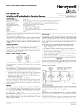
1. Wire the sensor base (supplied separately) per the wiring diagram, see Figure 1.
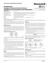
2. Set the desired address on the sensor address switches, see Figure 2.
3. Install the sensor into the sensor base. Push the sensor into the base while turning it
clockwise to secure it in place.
4. After all sensors have been installed, apply power to the control unit and acti-
vate the communication line.
5. Test the sensor(s) as described in the TESTING section of this manual.
SPECIFICATIONS
Operating Voltage Range: 15 to 32 VDC
Standby Current: 330µA @ 24 VDC (one communication every 5 sec. with LED blink enabled)
Max. Alarm Current (LED on:) 6.5 mA @ 24 VDC
Operating Humidity Range: 10% to 93% Relative Humidity, noncondensing
Operating Temperature Range: 0°C to 38°C (32°F to 100°F); U.S.
–10°C to 50°C (14°F to 122°F); Europe (this range not evaluated by UL)
Height: 1.7 inches (43 mm) installed in B210LP Base
Diameter: 6.1 inches (155 mm) installed in B210LP Base
4.1 inches (104 mm) installed in B501 Base
Weight: 5.0 oz. (142 g)
Additional Bases Available: All 200/500 Series bases are compatible.
I56-0058-008R
TESTING
Before testing, notify the proper authorities that the system is undergoing mainte-
nance, and will temporarily be out of service. Disable the system to prevent unwanted
alarms.
All sensors must be tested after installation and periodically thereafter. Testing meth-
ods must satisfy the Authority Having Jurisdiction (AHJ). Sensors offer maximum
performance when tested and maintained in compliance with NFPA 72.
The sensor can be tested in the following ways:
A. Functional: Magnet Test (P/N M02-04-01 or M02-09-00)
This sensor can be functionally tested with a test magnet. The test magnet
electronically simulates smoke in the sensing chamber, testing the sensor
electronics and connections to the control panel.
1. Hold the test magnet in the magnet test area as shown in Figure 3.
2. The sensor should alarm the panel.
Two LEDs on the sensor are controlled by the panel to indicate sensor
status. Coded signals, transmitted from the panel, can cause the LEDs to
blink, latch on, or latch off. Refer to the control panel technical documen-
tation for sensor LED status operation and expected delay to alarm.
B. Smoke Entry: Aerosol Generator (Gemini 501)
The GEMINI model 501 aerosol generator can be used for smoke entry
testing. Set the generator to represent 4%/ft. to 5%/ft. obstruction as de-
scribed in the GEMINI 501 manual. Using the bowl shaped applicator,
apply aerosol until the panel alarms.
A sensor that fails any of these tests should be cleaned as described under CLEAN-
ING, and retested. If the sensor fials after cleaning, it must be replaced and returned
for repair.
When testing is complete, restore the system to normal operation and notify the
proper authorities that the system is back in operation.
CLEANING
It is recommended that the detector be removed from its mounting base to facilitate
cleaning. The detector is cleaned as follows:
CAUTION
Dust covers provide limited protection against airborne dust particles during ship-
ping. Dust covers must be removed before the sensors can sense smoke. Remove
sensors prior to heavy remodeling or construction.
1 I56-0058-008R
03-11

C0129-04
2
3
1
2
3
3
1
2
1
(–)
(+)
+-
UL LISTED COM
PATIBLE
CONTROL PANEL
CLASS A OPTIONAL WIRING
REMOTE
ANNUNCIATOR
(–)
(+)
NOTE: Before removing the detector, notify the proper authorities that the smoke
detector system is undergoing maintenance and will be temporarily out of service.
Disable the zone or system undergoing maintenance to prevent unwanted alarms.
1. Remove the detector cover by prying away the four side tabs with a small-
bladed screwdriver, and then pulling the cover from the base.
2. Vacuum the screen carefully without removing it. If further cleaning is required
continue with Step 3, otherwise skip to Step 7.
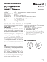
3. Remove the screen/chamber cover assembly by pulling it straight out (see Fig-
ure 4).
4. Clean the chamber by vacuuming or blowing out dust and particles.
5. Replace the sensing chamber cover, aligning the arrow on the top with arrow on
the printed circuit board.
6. To replace the screen, place it over the chamber assembly, turning it until it
snaps into place.
7. Replace the cover using the LEDs to align the cover and then gently pushing it
until it locks into place.
8. Reinstall the detector.
9. Test the detector as described in TESTING.
10. Reconnect disabled circuits.
11. Notify the proper authorities that the system is back on line.
FIGURE 1. WIRING DIAGRAM:
CAUTION
Do not loop wire under terminal 1 or 2. Break wire run to provide
supervision of connection.
LASER SAFETY INFORMATION
This smoke detector does not produce any hazardous laser radiation and is certified
as a Class 1 laser product under the U.S. Department of Health and Human Services
(DHHS) Radiation Performance Standard according to the Radiation Control for
Health and Safety Act of 1968.
Any radiation emitted inside the smoke detector is completely within the protective
housings and external covers. The laser beam cannot escape from the detector during
any phase of operation.
The Center of Devices and Radiological Health (CDRH) of the U.S. Food and Drug
Administration implemented regulations for laser products on August 2, 1976. These
regulations apply to laser products manufactured after August 1, 1976. Compliance is
mandatory for products marketed in the United States.
CAUTION
Use of controls, adjustments, or performance of procedures other than those specified
in this manual may result in hazardous radiation exposure.
SPECIAL NOTE REGARDING SMOKE DETECTOR GUARDS
Smoke detectors are not to be used with detector guards unless the combination has
been evaluated and found suitable for that purpose.
2 I56-0058-008R
03-11

C0169-00
C0146-00
FIGURE 2. ROTARY DECADE ADDRESS SWITCHES:
FIGURE 3. TEST MAGNET POSITION:
TENS ONES
9
8
7
6
5
4
3
2
1
0
9
8
7
6
5
4
3
2
1
0
D
N
T
N
I
A
P
T
O
O
TEST
MAGNET
TEST
MAGNET
PAINTED
SURFACE
MAGNET TEST
MARKER
LED STATUS
INDICATORS
PAINTED
SURFACE
C0170-00
FIGURE 4. SENSOR ASSEMBLY:
SENSOR COVER
COVER REMOVAL TABS
SCREEN ASSEMBLY
SENSING
CHAMBER
3 I56-0058-008R
03-11

System Sensor warrants its enclosed smoke detector to be free from defects in materials
and workmanship under normal use and service for a period of three years from date
of manufacture. System Sensor makes no other express warranty for this smoke detec
-
tor. No agent, representative, dealer, or employee of the Company has the authority to
increase or alter the obligations or limitations of this Warranty. The Company’s obligation
of this Warranty shall be limited to the repair or replacement of any part of the smoke
detector which is found to be defective in materials or workmanship under normal use
and service during the three year period commencing with the date of manufacture.
After phoning System Sensor’s toll free number 800-SENSOR2 (736-7672) for a Return
Authorization number, send defective units postage prepaid to: Honeywell, 12220 Rojas
FCC STATEMENT
This device complies with part 15 of the FCC Rules. Operation is subject to the following two conditions: (1) This device may not cause harmful interference, and (2) this device must
accept any interference received, including interference that may cause undesired operation.
NOTE: This equipment has been tested and found to comply with the limits for a Class A digital device, pursuant to Part 15 of the FCC Rules. These limits are designed to provide
reasonable protection against harmful interference when the equipment is operated in a commercial environment. This equipment generates, uses and can radiate radio frequency
energy and, if not installed and used in accordance with the instruction manual, may cause harmful interference to radio communications. Operation of this equipment in a residential
area is likely to cause harmful interference in which case the user will be required to correct the interference at his own expense.
THREE-YEAR LIMITED WARRANTY
Drive, Suite 700, El Paso TX 79936 USA. Please include a note describing the malfunc-
tion and suspected cause of failure. The Company shall not be obligated to repair or
replace units which are found to be defective because of damage, unreasonable use,
modifications, or alterations occurring after the date of manufacture. In no case shall the
Company be liable for any consequential or incidental damages for breach of this or any
other Warranty, expressed or implied whatsoever, even if the loss or damage is caused by
the Company’s negligence or fault. Some states do not allow the exclusion or limitation of
incidental or consequential damages, so the above limitation or exclusion may not apply
to you. This Warranty gives you specific legal rights, and you may also have other rights
which vary from state to state.
Please refer to insert for the Limitations of Fire Alarm Systems
0832
0832-CPD-0192
4 I56-0058-008R
©2016 System Sensor. 03-11
/