Example 1) Basic MTX3 system example (analog connections)
MTX Setup Manual
16
INPUT settings
Port select button
When you click this, the “Input Patch” dialog box will open. In this example we
are using the default settings, but if you want to switch to a different input port of
the MTX, click this button, choose the desired input port, and then click the
[Close] button.
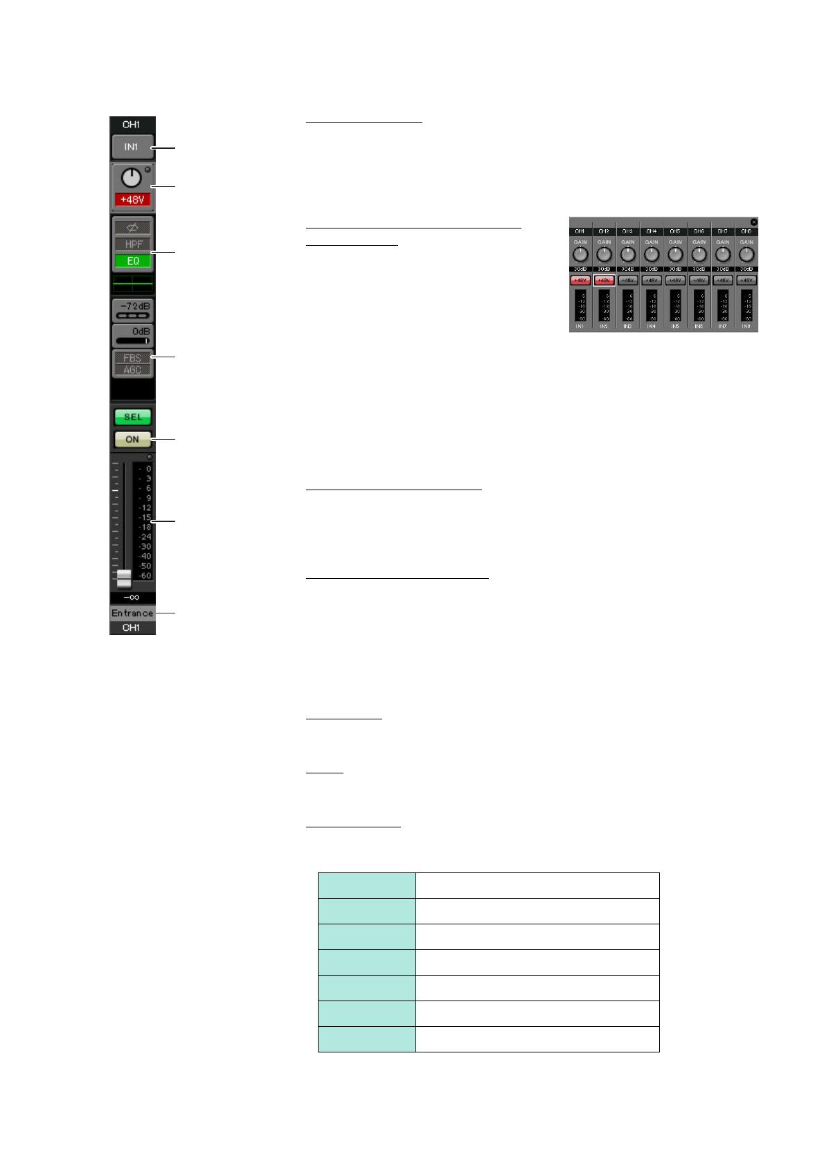
Port / External Device parameter
access button
This button lets you adjust the gain and turn
phantom power on/off. When you click the
button, a popup window will appear, allow-
ing you to adjust the gain and turn phantom
power on/off. Make the desired settings,
and then in the upper right, click × to close
the popup window. The appropriate gain level will depend on the devices that are
connected, so set the level appropriately for your devices.
For channels 1 through 8, the gain is set to 30 dB by default. Because condenser
microphones are connected to CH1 and 2, leave the gain at 30 dB and turn phan-
tom power on. Because wireless microphones are connected to CH3 and 4, lower
the gain to 0 dB.
EQ / HPF (High Pass Filter)
Click this to switch to the “CHANNEL EDIT” screen. Adjust the EQ and HPF
appropriately for the microphone you’re using. For ST IN, only EQ is available.
When you want to return to the “MAIN” screen, click the [MAIN] button.
FBS (Feedback suppressor)
FBS is provided on input channels 1 through 4. We recommend that microphone
inputs, and particularly movable microphones such as wireless microphones, be
connected to channels 1 through 4. When you click here, you will switch to the
FBS setting screen.
When you want to return to the “MAIN” screen, click the [MAIN] button.
For details on FBS settings, refer to “MTX-MRX Editor User Guide.”
[ON] button
This turns the channel on/off. You should turn off unused channels.
Fader
This adjusts the input level. Leave the fader at -∞ until the system goes online.
Channel name
You can double-click this to edit the name.
In this example, names have been assigned as follows.
CH1 Entrance
CH2 Kitchen
CH3 W.Mic1
CH4 W.Mic2
STIN1 CD Player
STIN2 BGM
STIN3 SD Player
Port select button
Port / External
Device parameter
access button
EQ / HPF
FBS (Feedback sup-
pressor)
[ON] button
Fader
Channel name


