Page is loading ...

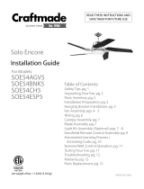
III. INSTALLATION OF WALL CONTROL
[PLEASE NOTE: Wall and/or handheld remote control must be used for
fan to operate. If you do not wish to use the wall control, please proceed
to Part IV for handheld remote control assembly instructions.]
A. Remove existing wall switch.
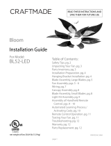
B. Wire one of the wall controls with wire connectors provided as
shown in Fig. 5.
WARNING: Do not mount wall control near heat-producing
equipment.
C. Wrap each wire connector separately with electrical tape as an
extra safety measure. Gently push wires and taped wire
connectors into outlet box.
D. Use a small screwdriver or ballpoint pen to set code switches on
the wall control by sliding them firmly to your choice of on or off /
left or right position. (Do not use factory setting/position.) (See
Fig. 5)
E. The dimmer switch (labeled D and O) has been pre-set to the
"ON" position (D). If you do not wish to have dimming capability
or are using bulbs that are not capable of being dimmed, please
move the switch to the "OFF" position (O). (See Fig. 5)
NOTE: Most LED and compact fluorescent bulbs are not
compatible for use with dimmer controls.
F. Install one 12-volt battery (included) in wall control. (See Fig. 5)
IMPORTANT: Wall control will not function unless battery is installed.
G. Select a faceplate (almond or white) and press firmly onto front of wall
control. Attach wall control to outlet box and secure with screws from
original wall switch. Attach wall plate (included) to wall control using 2
screws provided with the wall control. (See Fig. 5)
INSTALLATION AND OPERATING INSTRUCTIONS
I. SAFETY PRECAUTIONS
A. READ ALL INSTRUCTIONS AND SAFETY INFORMATION CAREFULLY BEFORE INSTALLING YOUR CONVERSION KIT AND SAVE THESE INSTRUCTIONS.
B. DANGER: HIGH VOLTAGE! Household electrical power can cause serious injury or death. Disconnect source of electrical power to the ceiling fan by removing fuse or switching off
circuit breaker. Make sure all electrical connections comply with local codes and ordinances, the National Electrical Code and ANSI/NFPA 70-1999. If you are unfamiliar with electrical
wiring, please use a qualified and licensed electrician.
C. CAUTION: TO REDUCE THE RISK OF FIRE OR ELECTRIC SHOCK, DO NOT USE THE FAN WITH ANY SOLID STATE SPEED CONTROL DEVICE OR CONTROL FAN SPEED
WITH A FULL RANGE DIMMER SWITCH.
D. Do not use this remote control with solid state ceiling fans.
Electrical source and fan must be 115/120 volts, 60 Hz. Maximum fan motor amps: 1; Maximum light watts: 360, incandescent only
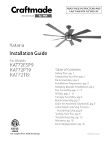
II. INSTALLATION OF RECEIVER
A. Disconnect source of electrical power to the ceiling fan by removing fuse
or switching off circuit breaker.
WARNING: Failure to disconnect power supply prior to installation may
result in serious injury.
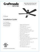
B. Loosen and/or remove screws from existing switch housing and lower
switch housing--save screws for later use. (See Fig. 1 for example.)
C. Disconnect existing wiring between motor housing and switch housing
and then remove existing switch housing. (See Fig. 1 for example.)
D. Remove screws from metal plate at top of replacement switch housing
and remove metal plate. (See Fig. 2)
E. Place receiver module inside replacement switch housing. Re-attach
metal plate with screws that were removed. [IMPORTANT: Metal plate
must be turned with the raised edge facing up.] (See Fig. 3)
F. Connect male plug from motor housing to female plug in receiver
module located inside replacement switch housing. (See Fig. 4 for
example.)
G. Make sure all wiring is tucked inside switch housing. Attach replacement
switch housing to motor housing with screws that were previously
loosened/removed. (See Fig. 4 for example.) Tighten all screws securely.
MODEL: ICS2 CONVERSION KIT
GENERAL INFORMATION
This remote control is designed to separately control your ceiling fan speed and, if applicable, light brightness.
There are eight buttons to control the fan and two buttons to control the lights.
p. 1
motor
housing
Fig. 1
switch housing
(existing)
receiver
module
metal
plate
metal
plate
raised edge
motor
housing
replacement
switch housing
Fig. 2
Fig. 3
Fig. 4
Fig. 5
Modifications not approved by the party responsible for compliance could
void the user's authority to operate the equipment.
*NOTE: This equipment has been tested and found to comply with the limits for a Class B digital device,
pursuant to Part 15 of the FCC Rules. These limits are designed to provide reasonable protection against
harmful interference in a residential installation. This equipment generates, uses and can radiate radio
frequency energy and, if not installed and used in accordance with the instructions, may cause harmful
interference to radio communications. However, there is no guarantee that interference will not occur
in a particular installation. If this equipment does cause harmful interference to radio or television
reception, which can be determined by turning the equipment off and on, the user is encouraged to try
to correct the interference by one or more of the following measures:
[representative drawing]
[representative drawing]
replacement
switch housing
replacement
switch housing
replacement
switch housing
* Reorient or relocate the receiving antenna.
* Increase the separation between the equipment and receiver.
* Connect the equipment into an outlet on a circuit different from that to which the
receiver is connected.
Consult the dealer or an experienced radio/TV technician for help.
1234
D
ON
O
L
DO
LEARN
M
H
1hr
3hr
6hr
12V
black (OUT to fan)
green
black
(AC IN from
breaker box)
black
(TO POWER supply)
black
green/
bare
ground
outlet box
wall control
face-
plate
12V battery
wall plate
dimmer
switch
code
switches

p. 2
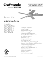
IV. ASSEMBLY OF HANDHELD REMOTE CONTROL
[NOTE: If you have already installed the wall control but do not wish to use the
handheld remote control, please proceed to Part V.]
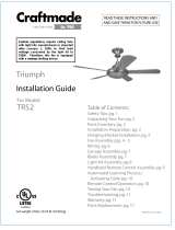
A. Gently pull on remote control cover to separate top and bottom parts.
(See Fig. 6)
B. Use a small screwdriver or ballpoint pen to set code switches on the wall
control by sliding them firmly to on or off / left or right position. (Do not use
factory setting/position). (See Fig. 7)
C. The dimmer switch (labeled D and O) has been pre-set to the "ON" position
(D). If you do not wish to have dimming capability or are using bulbs that are
not capable of being dimmed, please move the switch to the "OFF" position
(O). (See Fig. 7)
NOTE: Most LED and compact fluorescent bulbs are not compatible for use
with dimmer controls.
D. Install one 12-volt battery (included) in wall control. (See Fig. 7)
E. Align holes in wall control with posts located on inside of TOP part of remote
control cover and press together firmly. Carefully tuck each wire into the back
of the wall control to enable it to fit inside the remote control cover. Place
BOTTOM part of remote control cover over wall control, aligning posts in top
of remote control cover with post holes in the bottom. (Note narrower ends of
remote control cover before closing.) Squeeze top and bottom of remote
control cover together until you hear a click at each end, indicating that the
remote control cover has closed completely. (See Fig. 8)
V. AUTOMATED LEARNING PROCESS/ACTIVATING CODE
CAUTION: The wall control/handheld remote control can be
programmed to multiple receivers or fans. If this is not desired and there are
other programmable receivers or fans within a range of 40 feet programmed
with a unique code, turn wall switch off to those fans before programming
this fan.
A. Restore electrical power and then, if using wall control, set slider switch on
wall control to the ON position. Within 60 seconds of turning on the wall
control, press and hold the LEARN button on the wall control for 5 seconds or
until the fan switches to MEDIUM speed. (See Fig. 8)
B. Turn power OFF again for at least 5 seconds and then turn power back on.
Within 60 seconds of restoring the power, press and hold the LEARN button
on the handheld remote control for 5 seconds to synchronize remote to fan.
(See Fig. 8)
C. Test the fan function (and, if applicable, the light function) to confirm the
learning process is complete.
D. Attach black faceplate to front of wall control; press down firmly. (See Fig. 8)
Fig. 6
wall control
faceplate
remote control
cover, BOTTOM
post
hole
post
hole
remote control
cover, TOP
(top)
(bottom)
remote control
cover
wall control
handheld
remote control
12V battery
Fig. 6
CRAFTMADE Ceiling Fans
COPPELL, TX 75019
FOR CUSTOMER SERVICE, CALL: 1-800-486-4892
Fig. 7
Fig. 8
Fig. 9
CAUTION:
TO REDUCE THE RISK OF FIRE OR ELECTRIC SHOCK, DO NOT USE
THE FAN WITH ANY SOLID STATE SPEED CONTROL DEVICE OR
CONTROL FAN SPEED WITH A FULL RANGE DIMMER SWITCH.
L
M
H
1hr
3hr
6hr
OFF ON
L
M
H
1hr
3hr
6hr
OFF ON
1234
D
ON
O
L
DO
LEARN
M
H
1hr
3hr
6hr
12V
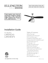
VI. REMOTE CONTROL--CARE AND OPERATION
A. Store the remote control away from excess heat or humidity.
B. To prevent damage to remote control, remove the battery if not used for long
periods of time.
C. Operation buttons on front panel of remote/wall control (See Fig. 9):
turns fan to LOW speed
turns fan to MEDIUM speed
turns fan to HIGH speed
sets 1-hour delay timer for OFF
(remains on last fan speed selected)
sets 3-hour delay timer for OFF
(remains on last fan speed selected)
sets 6-hour delay timer for OFF
(remains on last fan speed selected)
REVERSES blade direction (fan must be set on
low before reversing blade direction)
turns fan OFF
controls BRIGHTNESS and ON/OFF for lighted
housing/up-light
[not applicable on all fan models]
controls BRIGHTNESS and ON/OFF for light kit
[not applicable on all fan models]
turns wall control ON/OFF
(switch not functional on handheld remote)
The light function is controlled by pressing the or button. Hold the
or button down to increase or decrease light. Tap button quickly to
turn light(s) off or on. If you press button in excess of 0.7 seconds it becomes a
dimmer. The light varies cyclically in 0.8 seconds. The light button has auto
resume, so the light will stay at the same brightness as the last time it was
turned off.
IMPORTANT NOTE: The 1Hr, 3Hr and 6Hr timer buttons will only work when
the fan is set on LOW, MEDIUM or HIGH speed. If the light is on when a timer
button is used, it will remain on with the fan until the pre-set time limit is up
or until the “fan OFF” button and/or the light button is pressed.
VII. TROUBLESHOOTING GUIDE
Remote and/or wall control fail(s) to operate:
1. Make sure there is power to the receiver.
2. Make sure the switch housing has been re-wired correctly.
3. Make sure the battery in the handheld remote control and/or the
wall control is good.
4. The learning process between fan, handheld remote control and, if
applicable, wall control may not have been successful. Turn power
off and repeat Part V (Automated Learning Process) above.
dimmer
switch
button
button
button
button
button
button
button
button
button
button
slider switch
L
M
H
1Hr
3Hr
6Hr
wall
control
1234
D
ON
O
L
DO
LEARN
M
H
1hr
3hr
6hr
12V
code
switches
LEARN
/