Applied Motion Products SV7-C User guide

Type
User guide

Applied Motion Products SV7-C is a versatile servo drive designed to provide precise and efficient control of various servomotors. It offers advanced features for easy setup, tuning, and configuration, making it suitable for various applications requiring precise motion control. With its compatibility with CANopen networking, it enables flexible communication and integration within automation systems. The SV7-C's ability to handle DC power input ranging from 24 to 80 VDC makes it adaptable to diverse power requirements.

Applied Motion Products SV7-C is a versatile servo drive designed to provide precise and efficient control of various servomotors. It offers advanced features for easy setup, tuning, and configuration, making it suitable for various applications requiring precise motion control. With its compatibility with CANopen networking, it enables flexible communication and integration within automation systems. The SV7-C's ability to handle DC power input ranging from 24 to 80 VDC makes it adaptable to diverse power requirements.

SV
SV7-C Quick Setup Guide
Requirements
A compatible servo motor
A small at blade screwdriver for tightening the connectors (included).
A personal computer running Microsoft Windows 98, 2000, ME, NT, XP, Vista or 7/8/10/11.
Quick Tuner™ software (version 2.2.18 or later) available at www.applied-motion.com/products/software.
An RS-232 Applied Motion programming cable (included)
4 pin spring connector (included) for connecting to the CAN network.
For more detailed information, please download and read the SV7 Hardware Manual, available at www.applied-motion.com/support/manuals.
To begin, make sure you have the following equipment:
920-0064B
Step 1
a) Download and install the QuickTuner™ software.
b) Launch the software by clicking:
Start / Programs / Applied Motion Products / Quick Tuner
c) Connect the drive to your PC using the supplied programming cable. If your PC does
not have a serial port you will need a USB to serial port (RS-232) adapter.
Step 2
a) Connect the I/O
b) Connect the Encoder
Applied Motion motor
cables are available with
connectors that mate
directly to the encoder
connector on the drive.
encoder Z+ (5)
Hall 1-(10)
encoder B- (4)
Hall 1+ (9)
encoder B+ (3)
Hall 3+ (13)
Hall 3- (14)
SHLD (15)
(12) Hall 2-
(11) Hall 2+
(6) encoder Z-
(1) encoder A+
(7) +5VDC 200mA
(2) encoder A-
(8) GND
Front View
ENCODER
Front View
X COMMON
not used
X3 / Enable
X5 / CWJOG
X4 / Alarm Reset
Analog IN2
Analog IN1
X2 / DIR-
X2 / DIR+
X1 / STEP +
X1 / STEP -
GND
GND
+5V OUT
Y COMMON
Y3 / FAULT
Y2 / MOTION
Y1 / BRAKE
18
17
16
15
14
13
12
11
10
9
8
7
6
5
4
2
3
1
19
20
21
22
23
24
25
X6 / CCWJOG
IN/OUT
X8/CCWLIMIT+
X8/CCWLIMIT-
X7/CWLIMIT-
X7/CWLIMIT+
Y4-
Y4+
4
3
2
1
0
F
E
D
C
B
A
9
8
7
6
5
4
3
2
1
0
7
6
5
V+
V-
Motor A (or U) phase
Motor B (or V) phase
Motor C (or W) phase
Motor
Grounding
Screw
Leave this pin
unconnected
Step 3
a) Wire the drive to the DC power source.
(Do not apply power until all connections to the
drive have been made.)
Note, the SV7 drives accept DC power from 24-80
VDC.
b) Wire the servo motor to the drive.
For a non-Applied Motion Products motor, please
refer to your motor specs for wiring information.
Be sure to connect the motor case ground to the
grounding screw as indicated, leaving the last pin
on the motor/power connector unconnected.
Step 5 - CANOpen Setup
a) Connect to CAN network.
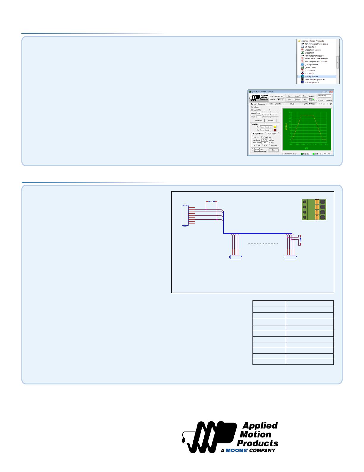
Applied Motion Products SV7-C drives use a four-pin spring con-
nector, that conforms to the DR303 specication. The connector
should be wired in a daisy-chain conguration with a 120 Ohm
resistor used to terminate each end.
Switch Setting Resultant Bit Rate
0 1 Mbps
1 800kbps
2 500 kbps
3 250 kbps
4 125 kbps
5 50 kbps
6 20 kbps
7 12.5 kbps
8n/a
9 n/a
Bit Rate Table
Step 4 - Configuration
a) Within the Quick Tuner™ software, select the correct COM port and apply power to the drive.
b) If using an Applied Motion servomotor, press the “Open” button and select a
factory tuning le, paying close attention to the voltage and inertia ratio.
c) Apply power to the drive.
d) Select the “Motor - Encoder” tab and conrm settings for motor current, pole
count, and encoder resolution. For non-AMP motors, these data must be obtained
from your motor’s datasheet. Execute the Timing Wizard, following the on-screen
prompts. This will ensure the drive can properly commutate the motor.
e) Use the “Tuning - Sampling” tab to tune the motor. Consult the Quick
Tuner™ Software Manual for step-by-step tuning instructions.
f) Go to the “Inputs - Outputs” tab to specify any dedicated I/O functions required by the application.
g) Press the “Download” button to save all setings to the drive’s non-
volatile memory. Your drive is now congured for use.
The Quick Tuner™ manual should be considered required
reading for anyone tuning a servo system.
18645 Madrone Pkwy
Morgan Hill, CA 95037
Tel: 800-525-1609
applied-motion.com
If you have any questions or comments,
please call Applied Motion Products
Customer Support: (800) 525-1609,
or visit us online at applied-motion.com.
5
5
4
4
3
3
2
2
1
1
D D
C C
B B
A A
CAN_GND
CAN_SHLD
CAN_H
CAN_SHLD
CAN_L
CAN_GND
CAN_L
CAN_H
CAN_H
CAN_SHLD
CAN_L
CAN_GND
Title
Size Document Number Rev
Date: Sheet of
N/A A
CANopen Network Cable for Applied Motion Drives and Kvaser LeafLight HS
A
11Monday, November 24, 2008
Title
Size Document Number Rev
Date: Sheet of
N/A A
CANopen Network Cable for Applied Motion Drives and Kvaser LeafLight HS
A
11Monday, November 24, 2008
Title
Size Document Number Rev
Date: Sheet of
N/A A
CANopen Network Cable for Applied Motion Drives and Kvaser LeafLight HS
A
11Monday, November 24, 2008
n*
R termination:
Network must be terminated
at each end with a 120 ohm
resistor.
n:
Cable may be made with up to 254
drive connectors. Termination is
only required at each end.
CAN_BUS
DSUB9 FemaleDSUB9 Female
1
2
3
4
5
6
7
8
9
.1" Spacing Spring Plug.1" Spacing Spring Plug
4
3
2
1
R termination*
120 ohm nominal
R termination*
120 ohm nominal
.1" Spacing Spring Plug.1" Spacing Spring Plug
4
3
2
1
R termination*
120 ohm nominal
R termination*
120 ohm nominal
b) Set BitRate, Node ID
The SV7-C has three CAN network-related settings, one for Bit Rate and two for Node ID. The Bit Rate
is congured using an eight-position switch. See Bit Rate table for the Bit Rate settings. The Node ID
is congured using a sixteen position switch to set up the lower four bits of the Node ID. The upper
three bits of the Node ID are set using an additional 8 position switch located under the cover on the
CANOpen motherboard. Valid ranges for the Node ID are 0x01 through 0x7F. Node ID 0x00 is reserved
in accordance with the DS301 specication.
Note: The Node ID and Bit Rate are captured only after a power cycle, or after a network reset com-
mand has been sent. Changing the switches while the drive is powered on will NOT change the Node
ID or Bit Rate until one of these conditions has been met.
GND
CAN_L
SHLD
CAN_H
920-0064B
  • Page 1 1
  • Page 2 2

Applied Motion Products SV7-C User guide

Type
User guide

Applied Motion Products SV7-C is a versatile servo drive designed to provide precise and efficient control of various servomotors. It offers advanced features for easy setup, tuning, and configuration, making it suitable for various applications requiring precise motion control. With its compatibility with CANopen networking, it enables flexible communication and integration within automation systems. The SV7-C's ability to handle DC power input ranging from 24 to 80 VDC makes it adaptable to diverse power requirements.

Ask a question and I''ll find the answer in the document

Finding information in a document is now easier with AI