Westinghouse ETL-ES-Thurlow-WH21 Owner's manual
- Category
- Household fans
- Type
- Owner's manual
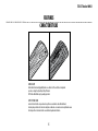
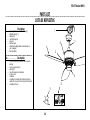
Westinghouse ETL-ES-Thurlow-WH21 is a stylish ceiling fan that will complement the décor of your home while also providing ample airflow. It features two high-quality finishes on one blade, allowing you to change the style with just a flip of the blade. The fan can be mounted on both normal and sloped ceilings and comes with a handheld remote control for convenient operation. Installation requires a qualified electrician and should be mounted to an outlet box marked suitable for fan support.
Westinghouse ETL-ES-Thurlow-WH21 is a stylish ceiling fan that will complement the décor of your home while also providing ample airflow. It features two high-quality finishes on one blade, allowing you to change the style with just a flip of the blade. The fan can be mounted on both normal and sloped ceilings and comes with a handheld remote control for convenient operation. Installation requires a qualified electrician and should be mounted to an outlet box marked suitable for fan support.


-
 1
1
-
 2
2
-
 3
3
-
 4
4
-
 5
5
-
 6
6
-
 7
7
-
 8
8
-
 9
9
-
 10
10
-
 11
11
-
 12
12
-
 13
13
-
 14
14
-
 15
15
-
 16
16
-
 17
17
-
 18
18
-
 19
19
-
 20
20
-
 21
21
-
 22
22
-
 23
23
-
 24
24
-
 25
25
-
 26
26
-
 27
27
-
 28
28


Westinghouse ETL-ES-Thurlow-WH21 Owner's manual
- Category
- Household fans
- Type
- Owner's manual
Westinghouse ETL-ES-Thurlow-WH21 is a stylish ceiling fan that will complement the décor of your home while also providing ample airflow. It features two high-quality finishes on one blade, allowing you to change the style with just a flip of the blade. The fan can be mounted on both normal and sloped ceilings and comes with a handheld remote control for convenient operation. Installation requires a qualified electrician and should be mounted to an outlet box marked suitable for fan support.
Ask a question and I''ll find the answer in the document
Finding information in a document is now easier with AI
in other languages
Related papers
-
Westinghouse 7226200 Owner's manual
-
Westinghouse 7207600 User manual
-
-
Westinghouse 7200600 User manual
-
-
-
Westinghouse 7247700 Operating instructions
-
Westinghouse 7224200 User manual
-
-


