Page is loading ...

MODEL SKR60
OPERATING MANUAL

2
9
8
5
4
1
3
2
6
7
10
11
12
13
14
15
16
17

3
Thank you for buying the manual laser.
Although the SKR60 is very simple to use, we
recommend that you read this manual before
operating the laser.
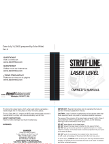
Description
1. Laser apertures
2. Rotating head
3. Horizontal vial Y
4. Horizontal vial X
5. Vertical vial
6. Leveling knob Y
7. Leveling knob X
8. Adjustable wall mount
9. Height adjustment clamp
10. Keypad
11. Adjustable feet for vertical setup
12. Grid clamp
13. Batteries
14. Wall mount release
15. Adjustable slope lock
16. Tripod mounts
17. Slope angle index
Keypad
Increase or
Decrease Rotation
Speed / Scan
Length
On / Off
Rotation /
Scanning
Modes

4
Specifications
Recommended use 30 m (100 ft.) radius
Accuracy +/- 1 cm at 30 m
(+/- 3/16” at 50 ft.)
Rotation speed 0, 150, 400, 600 rpm
Scanning length 2°, 8°, 25°
Batteries 3 AA alkaline batteries
Working time 30 hours
Weight 4 lbs. (2 kg)
Dimensions 6 3/4" x 5" x 5"
170 x 120 x 140 mm
Laser diode Visible 635 nm; <5mW:
Class IIIR/Europe
Class IIIa/US
Horizontal Setup
1) Put the SKR60 on a flat surface or tripod, or use
the wall mount (see “ceiling grid” or “tripod”
sections).
2) To level the laser, center the bubbles in the
horizontal vials by turning leveling knobs X and Y.
The bubbles move in the direction you turn the
knobs. Level one vial, then the other, then make fine
adjustments to both.
3) Turn the laser on by pressing the on/off key.
Vertical Setup
1) Put the SKR60 in vertical position on a flat
surface or tripod.
2) Level the laser using the adjustable feet (11) and
leveling knob Y to center the bubble in the vertical
vial.
3) Turn the laser on by pressing the on/off key.

5
Rotation Speed
The head rotates at three speeds; 150 rpm is the
default setting. To change rotation speed, press the
3
rd
key (speed/scan) on the keypad. Press once for
400 rpm; press again for 600 rpm (it takes a few
seconds to reach full acceleration). Press again to
stop rotation.
The laser beam is more visible in slow motion.
To move the beam left or right, use the remote
control with the laser in scanning mode. It’s also
possible to stop the rotation and point the beam
manually.
Scanning
Scanning mode allows you to see the beam easier at
a distance. To switch from rotation to scan, press the
R/S key. The scanning beam has three lengths, or
angles: 2°, 8°, and 25°. To change, press the 3
rd
key
(speed/scan) on the keypad.
When using the laser, it is important to check that it
has not been moved and that your setting is still
accurate.

6
Using the Built-in Wall Mount
Setup on Ceiling Grid
1) To hang the SKR60 from a ceiling grid, open the
height adjustment clamp (9) on the side of the wall
mount. Raise to the height desired and lock.
2) Open the top grid clamp (12), place the wall
mount against the grid, and lock. The grid cannot be
thicker than 1/8’’(3mm).
3) Use the height adjustment clamp for final
positioning. Level the laser. Check that both vials
are still centered whenever laser position is changed.
Height
adjustment
clamp (9)
Grid
clamp (12)
Adjustable
slope lock (15)
Tripod mount
(16)

7
The laser can also be fastened to the wall with nails,
using the 2 holes in the wall mount plate.
Setup on a Tripod
There are two standard 5/8-11 tripod mounts: one on
the bottom of the laser for horizontal mode, the other
on the wall mount for vertical mode.
A camera tripod mount is located on the other side
of the wall mount for both horizontal and vertical
modes.
After attaching the laser to the tripod, be sure to
level the bubbles as described on page 4.
Changing mounts:
1) To switch from the 5/8-11 to camera tripod mount,
take out the wall mount plate by opening the height
adjustment clamp (9) and pressing the wall mount
release (14).
2) Rotate the plate, slide it back into the wall mount,
and lock the clamp (9).
Using the laser in horizontal mode on tripod:
1) Use the tripod mount (16) to attach the laser to the
tripod.
2) To position the laser so that the rotating beam is
horizontal, open the adjustable slope lock (15). Tilt
the laser 90° (the full extent you can move it).
3) Level the bubble as described under “Horizontal
Setup.”

8
Using the laser in vertical mode on tripod:
1) Use the tripod mount (16) to attach the laser to the
tripod.
2) Level vertical bubble vial as described under
“Vertical Setup.”
Slope
The SKR60 can be inclined up to 90° to lay out
stairways and cathedral ceilings.
1) Holding the laser in vertical position, attach laser
to the tripod using the 5/8-11 mount on the wall
mount.
2) Unlock the adjustable slope clamp(15). Tilt the
laser 90° (the full extent you can move it) and lock.
3) Center the bubbles to level the laser (see p.4)
4) Unlock the adjustable slope clamp. Tilt the laser
until you reach the desired grade as shown on slope
angle index (17) and lock.
Changing the batteries
When battery power is low, the laser will stop
rotating and the laser beam will blink.
1) The battery compartment (13) is located behind
the wall mount. Release clamp (15) to access it.
2) Replace batteries with 3 new AA alkaline
batteries, matching polarity (– and +) as indicated in
the compartment. Replace all 3 at once.

9
How to check the laser
Here are a few simple instructions to check your
laser for calibration. Remember that the laser is a
precision instrument and that it is important that you
keep it calibrated and in proper condition.
The accuracy of your work is completely your
responsibility and you should regularly check your
instrument, especially prior to important jobs.
Horizontal checking (X and Y axis)
The laser has 2 horizontal axes; both ends of each
axis must be checked for calibration.
1) Place the laser on a flat surface 15m (50 feet)
from a wall. To check the first axis, position it so
that the Y leveling knob is facing the checking wall.
2) Center the bubbles in the horizontal vials by
turning leveling knobs X and Y. The bubbles move
in the direction you turn the knobs. Level one vial,
then the other, then make fine adjustments to both.
3) Turn the laser on. Stop the rotation so that the
beam is a point.
4) Mark the location of the center of the beam.
5) Rotate the laser 180°. Check that X and Y bubbles
are still centered. Mark the location of the center of
the beam on the wall, close to the first mark.
Y axis
X axis

10
6) Both marks should be at the same place. At 15m.,
the marks should be no more than 1cm apart.
(At 50 ft, no more than 3/8” apart). If the two marks
are not close enough, your laser has to be calibrated.
7) To check the second axis, turn the laser 90° so
that the X leveling knob is facing the checking wall.
Repeat the same steps: level the laser, mark the
beam, rotate 180°, level the laser, and mark again.
If you notice an error, please contact your dealer or
factory service center to have it calibrated.
Cone error checking
1) Set up the laser about 1m away from a wall (a) or
pole and 30 m from another wall (b) or pole (about
2 ft away from near wall; 100 ft from far wall.)
Level the laser with leveling knobs and vials.
2) Turn the laser on. Stop the rotation and mark the
location of the beam on the near wall (a). Always
mark the center of the beam.
3) Rotate your laser 180° and level the laser again.
Mark the location of the beam on the far wall (b).
4) Now set up the laser about two feet away from the
far wall. Level the laser again. Stop the rotation and
mark the beam (b’) near the first mark (b).
5) Rotate your laser 180° and level the laser again.
Mark the location of the beam on the other wall (a’),
near the first mark (a).
6) Compare the two sets of marks on the walls. If the
difference between aa’-bb’ exceeds 3/4” (2 cm),
contact your local service center.

11
Remote control
The optional remote control stops, starts, or changes
direction of laser rotation and controls scanning.
Care and Handling
Use of controls or adjustments or performance of
procedures other than those specified herein may
result in hazardous radiation exposure.
The Manual Laser is a precision instrument
which must be handled with care. Avoid shock
and vibrations. Always store and transport the laser
and its accessories in the carrying case.
Although weather resistant, you must always keep
your laser and its accessories dry and clean after
using. This will increase the battery life.
Do not store your laser at temperatures below –4°F
(-20°C) or above 176°F (80°C) because the
electronic components could be damaged.
Do not store your instrument in its case if the
instrument or the case are wet to prevent water
condensation inside the instrument.
Rotation left /
Move scan left
Rotation right /
Move scan right
Rotation/Scanning
Toggle Key
Increase rotation
speed or scan
length
Decrease rotation
speed or scan
length
Battery

12
To maintain the precision of the SKR60, check it
regularly.
Keep the lenses of the apertures clean. Use a soft
cloth or glass cleaner.
Design Patents Pending

13
SKR60
MANUEL D’UTILISATION
Nous vous remercions d’avoir acheté le laser rotatif
manuel SKR60.
Bien que très simple d’utilisation, nous vous
recommandons vivement de lire ce manuel avant
d’utiliser votre laser.
Description
1. Sorties laser
2. Tête rotative
3. Nivelle de calage horizontal Y
4. Nivelle de calage horizontal X
5. Nivelle de calage vertical
6. Bouton de calage Y
7. Bouton de calage X
8. Support mural ajustable
9. Levier de réglage de la hauteur
10. Clavier
11. Pied ajustable
12. Levier de serrage sur cornière
13. Emplacement des piles
14. Levier de déblocage pour retournement
de la plaque
15. Levier de blocage pour plan incliné
16. Insert pour trépied
17. Index

14
Clavier
Spécifications
Emission Laser Diode Visible 635nm
<5mW, Classe IIIR
Distance d’utilisation
recommandée 30m de rayon
Précision +/- 1 cm à 30 m.
Vitesse de rotation 0- 150 - 400 – 600 t/m
Autonomie 30 heures
Piles 3 piles Alcaline Type
AA
Angles de scanning 2° / 8° / 25°
Degré d’étanchéité IP64
Poids 2 Kg
Dimensions 170 x 120 x 140 mm
Utilisation
Mise en place horizontale
1°) Mettre le SKR60 sur une surface plane ou sur un
trépied. Tourner les boutons de calage X et Y afin de
centrer précisément les bulles dans les nivelles de
calage horizontal X et Y.
NB : Les bulles bougent dans la direction où vous
tournez les boutons de calage.
Sélection
Vitesse de rotation /
Angles de scanning
Marche /
Arrêt
Sélection
Mode Rotation /
Mode Scanning

15
2°) Allumer le laser en appuyant sur la touche
Marche / Arrêt du clavier.
3°) Ajuster la rotation de la tête en appuyant sur la
touche de sélection de la vitesse de rotation.
La vitesse de rotation par défaut est de 150 t/m. En
appuyant de nouveau sur la touche de sélection de la
vitesse, vous pourrez ajuster la vitesse de rotation à
400 et 600 t/m. Pour stopper la rotation de la tête,
appuyer de nouveau sur cette touche.
NB : Les différentes vitesses de rotation sont
disponibles quelques secondes après avoir pressé la
touche de sélection.
Il peut être nécessaire d’ajuster la vitesse de rotation
de tête selon les conditions lumineuses. Le rayon
laser est davantage visible à vitesse lente. Il est
possible de stopper la rotation de la tête et de
déplacer le point laser manuellement pour voir le
point laser à longue distance.
4°) Pour passer en mode scanning, appuyer sur la
touche de sélection Rotation / Scanning (R/S). Trois
angles de scanning sont possibles ( 2° - 8° - 45°).
Appuyer sur la touche de sélection d’angles de
scanning pour choisir l’angle désiré.
5°) Pour déplacer le plan latéralement à l’aide de la
télécommande, votre SKR60 doit être
impérativement en mode scanning.

16
Utilisation du support mural intégré
Installation sur une cornière
1) Pour installer le SKR60 sur une cornière, ouvrir le
levier situé sur le dessus de l’appareil (8).
2) Faites glisser le support sur la cornière et bloquer
le support en refermant le levier.
L’épaisseur maximum de la cornière ne doit pas
excéder 3mm (1/8”).
Blocage /
Déblocage
pour réglage
de la
hauteur
Blocage /
Déblocage
sur cornière
Inserts pour
trépieds
Blocage /
Déblocage
pour
inclinaison

17
3) Pour régler la hauteur du laser, ouvrir le levier
situé sur le côté du laser(9). Faites alors glisser le
laser et bloquer le levier à la hauteur désirée.
4) Il est également possible de fixer le support sur un
mur à l’aide de vis ou de clous que vous disposerez
dans les trous du support prévus à cet effet.
Installation sur un trépied
Deux types d’inserts sont proposés. Ceux-ci se
trouvent de chaque coté du support mural (12).
L’appareil vous est livré en version utilisable sur un
trépied standard (5/8’’).
Toutefois, si vous souhaitez utiliser un trépied photo :
1. Débloquer le levier permettant le réglage
de la hauteur du support
2. Appuyer sur le loquet situé de l’autre coté
du support
3. Faites glisser le support jusqu’à le sortir
complètement des glissières
4. Retourner le support et insérer le de
nouveau dans les glissières.
Pour utiliser l’appareil en mode vertical sur un
trépied standard, visser simplement le support dans
la vis du trépied (16).
Réaliser un plan incliné
1. Fixer votre laser sur un trépied (16)ou sur une
surface plane.
2. Débloquer le levier de blocage (15) situé sur le
coté de l’appareil.

18
3. Incliner alors l’appareil jusqu’à obtention de la
pente désirée.
4. Bloquer alors l’inclinaison en refermant le levier.
Il est possible d’incliner l’appareil à 90°.
Remplacement des piles
1. Ouvrir la trappe pile située sur l’arrière de
l’appareil (13)
2. Retirer les anciennes piles et les remplacer par
des nouvelles* en respectant la polarité indiquée sur
le fond du logement.
3. Refermer la trappe pile.
*Utiliser impérativement des piles alcalines de
bonne qualité.
Comment vérifier votre laser
Nous vous donnons ci-après quelques informations
concernant la vérification de la bonne calibration de
votre appareil.
Souvenez-vous que votre laser est un appareil de
précision et, qu’en tant que professionnel, il est
important que vous le gardiez réglé dans des
conditions convenables.
La précision de votre travail est totalement sous
votre responsabilité et il est important de
contrôler votre laser régulièrement, spécialement
avant tout travail important.
Merci de suivre les instructions suivantes pour
vérifier le bon réglage de votre appareil.

19
Contrôle horizontal (Axes X et Y)
1) Placer le laser sur une surface plane à environ 30
mètres d’un mur. Positionner le laser de manière à
ce que le bouton de réglage de l’axe Y (6) soit face
au mur.
2) Tourner le bouton de calage X(7) et Y(6) jusqu’à
centrer les bulles dans les nivelles X (3)et Y(4).
3) Pointer le point laser manuellement sur le mur et
noter la marque X1.
4) Faites pivoter le laser de 180°. Vérifier que les
bulles soient toujours centrées dans les nivelles X et
Y. Pointer alors le point laser sur le mur puis
marquer le point X2.
5) Les deux marques X1 et X2 doivent être au même
niveau (dans la tolérance, soit à +/- 1cm à 30 mètres).
Si l’espacement des deux marques est supérieur à +/-
1cm à une distance de 30 mètres, contacter votre
service après-vente local.
6) Pour l’axe Y, positionner votre laser à 30 mètres
de manière à ce que le bouton de calage Y soit face
au mur. Répéter alors la procédure de vérification
comme décrite ci-dessus.
Axe Y
Axe X

20
Contrôle d’erreur conique
1. Positionner votre laser sur un trépied dans une
pièce à environ 1 mètre d’un mur ou d’une mire que
nous appellerons (a) et 30 mètres d’un autre mur que
nous appellerons (b). Mettre en marche le laser.
2. Après avoir mis votre laser de niveau, stopper la
rotation et noter l’impact du rayon sur le mur (a).
3. Faites pivoter votre laser de 180° et noter l’impact
sur le mur (b).
4. Placer le laser à environ 1 mètre du mur (b).
Après avoir calé votre laser, noter l’impact sur le
mur (b’).
5. Faites pivoter votre laser de 180° et noter l’impact
sur le mur (a’).
6. Comparer les deux séries de mesures.
aa’ – bb’ < 9mm. Si ce n’est pas le cas, contacter
votre service après-vente local.
Télécommande
La télécommande TL15 est disponible en option.
Elle vous permettra de commander votre SKR60
jusqu’à une distance de 30 mètres environ.
/