20
7.6.2 Maximum dimensions of the connections
ForfixedversionHD4/Rcircuit-breakers,theconnectionsmust
be shaped and installed in accordance with the indications
given in the overall dimensions and in compliance with the dis-
tances indicated.
7.6.3 Surface treatment of the connections
The connections can be made of bare copper or bare alumin-
ium.However,itisalwaysadvisabletosilver-platethecontact
surfaces.
The thickness of the surface treatment must be even and regu-
lar.
7.6.4 Assembly of the connections
– Make sure that the contact surfaces of the connections are
perfectlyflatandwithoutburrs,tracesofoxidationorde-
formities caused by drilling or impact sustained.
– Depending on the conductive material used and the surface
treatment given, the operations indicated in the following
table must be carried out on the surface contact of the con-
ductor.
Bare copper
Clean with a fine file or emery cloth
Smear 5RX Moly
Copper or silver-
plated aluminium
Clean with a rough dry cloth
Only if there are traces of oxidation that are difficult
toshift,cleanwithultra-finegrainemergyclothand
take care not to remove the surface layer
Repeat the surface treatment if necessary
Bare aluminium
Clean with a metal brush or emery cloth
Immediately smear neutral grease over the contact
surfaces
Insert a bi-metal copper-aluminium strip with
beaded surfaces between the aluminium
connection and the copper terminal (copper side
touchingtheterminal,aluminiumsidetouchingthe
connection)
Assembly procedures
– Place the connections in contact with the circuit-breaker
terminals.
– Insert a spring washer and a flat washer between the head
of the bolt and the connection.
– The diameter of the flat washers must be able to distribute
the torquing pressure over a wide area.
– Tightenthebolt,takingcaretopreventtheinsulatingparts
from being stressed (consult the table with the rightening
torque values).
– Make sure that the connections do not exert any force on
the terminals.
– Carefully comply with the manufacturer’s instructions for
terminating the cables in cable connections.
Table of tightening torque values
Screw Tightening torque values
M6 10 Nm
M8 30 Nm
M10 40 Nm
M12 70 Nm
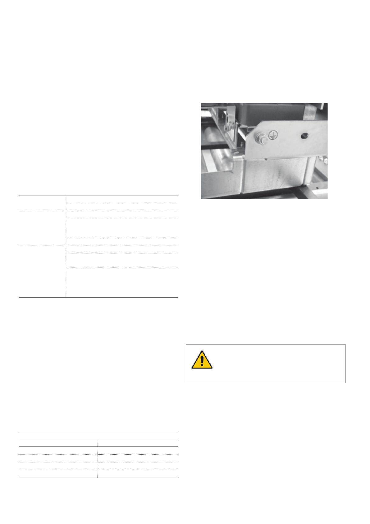
7.7 Earthing
– Earth fixed version circuit-breakers by means of the spe-
cial screw marked with the relative symbol. Clean and de-
grease the area around the screw corresponding to a diam-
eter of about 30 mm. Use a conductor (busbar or cord) with
a cross-section conforming to the Standards in force.
– Whentheassemblyiscompleted,coverthejointwithvase-
line grease.
7.8 Connection of the auxiliary circuits
The minimum cross-section of the wires used for the auxiliary
circuits must not be less than the one used for the internal
cabling.
Theymustalsobeinsulatedfor3kVtestvoltage.
7.8.1 Fixed version circuit-breakers
The auxiliary circuits of the circuit-breaker must be connected
by means of the terminal box installed in the circuit-breaker’s
operating mechanism.
The wires outside the circuit-breaker must be routed inside ap-
propriately earthed metal tubes or ducts.
Figure 8
Make sure that the circuit-breaker is open
and the closing springs discharged before
removing the operating mechanism cover to
access the terminal box.
7.8.2 Plug-in circuit-breaker
The auxiliary circuits of the plug-in or removable circuit-breaker
are fully wired in the factory through to the connector. Please
refer to the wiring diagram of the switchgear for the connec-
tions.