
Trumatic
E 2800
E 2800 A
E 4000
E 4000 A
Truma
Gerätetechnik GmbH & Co
Postfach 1252
D-85637 Putzbrunn
Service
Telefon 0049 (0)89 4617-142
Telefax 0049 (0)89 4617-159
e-mail: [email protected]
http://www.truma.com
Istruzioni per l’uso Pagina 23
Istruzioni di montaggio
Da tenere nel veicolo!
Gebrauchsanweisung
Seite 1
Einbauanweisung
Im Fahrzeug mitzuführen!
Operating instructions Page 8
Installation instructions
To be kept in the vehicle!
Mode d’emploi Page 15
Instructions de montage
À garder dans le véhicule !
Gebruiksaanwijzing Pagina 31
Inbouwhandleiding
In voertuig meenemen!
Brugsanvisning Side 39
Monteringsanvisning
Skal medbringes i køretøjet!
Instrucciones de uso Página 45
Instrucciones de montaje
¡Ilévalas en el vehículo!
Bruks- och monteringsanvisningar på svenska
kan rekvireras från tillverkaren Truma eller från
Truma-Service i Sverige.
Käyttö- ja asennusohjeita on saatavissa
Truma-valmistajalta tai Truma-huollosta.
Bruksanvisningen og monteringsveiledningen
på ditt språk kan fås hos produsenten Truma
eller hos Truma-Service i ditt land.
Τις δηγίες ρήσης και τπθέτησης στη
µητρική σας γλώσσα µπρείτε να τις λάετε
απ τν κατασκευαστή Truma ή απ τ
σέρις Truma στη ώρα σας.
Instruções de utilizaçaõ e de montagem
podem ser solicitadas junto ao fabricante Truma
ou da assistência técnica da Truma no seu país.
Návod k použití a montáži ve svém jazyce obdržíte
na požádání u firmy Truma nebo u jejího servisního
zástupce ve vaší zemi.
Návod na použitie a montážny návod vo Vašej
krajinskej reči si môžete vyžiadať u výrobcu
Truma alebo v servise Truma vo Vašej krajine.
A magyar nyelvü használati és szerelési utasítást
a gyártónál a Truma cégnél vagy a Truma
magyarországi képviseleténél lehet beszerezni.
Instrukcję obsługi i montażu w ojczystym
języku mogą Państwo dostać u producenta
(Truma) lub w serwisie Trumy w swoim kraju.

Einbaubeispiel
1 Bedienteil (nach Wahl)
2 Zeitschaltuhr
(Sonderzubehör)
3 Verbrennungsluft-Zuführung
4 Abgasführung
5 Elektronische Steuereinheit
6 Stromzuführung
7 Gasanschluß
W Warmluft
U Umluft
Esempio d´installazione
1 Quadro di comando (a scelta)
2 Orologio temporizzatore
(accessorio extra)
3 Aria dicombustione
4 Scarico gas
5 Scheda elettronica
6 Alimentazione elettrica
7 Collegamento gas
W Aria calda
U Aria di ritorno
Installatievoorbeeld
1 Bedieningspaneel
(speciale accessoire)
2 Tijdklokschakelaar
(extra onderdeel)
3 Verbrandingslucht
4 Rookgassen
5 Elektronischbesturingskastje
6 Stroomvoorziening
7 Gasaansluiting
W Warmelucht
U Omgeringslucht
Indbygningseksempel
1 Betjeningsdel (ønsket type)
2 Tidsur (ekstra tilbehør)
3 Forbrændingsluft-tilførsel
4 Forbrændingsgasudledning
5 Elektronisk styreenhed
6 Strømtilførsel
7 Gastilslutning
W Varmluft
U Cirkulationsluft
Installation example
1 Control panel (of your choice)
2 Time switch
(special accessory)
3 Combustion air
4 Flue gas
5 Electronic control unit
6 Power supply
7 Gas connection
W Warm air
U Return air
Example d’installation
1 Pièce de commande
(au choix)
2 Minuterie (en option)
3 Air de combustion
4 Gas d’échappement
5 Commande électronique
6 Alimentation électrique
7 Raccordement au gaz
W Air chaud
U Air de circulation
Einbauvarianten
Installation options
Variantes
d’installation
Varianti
d’installazione
Inbowvarianten
Indbygningsvarianter
Variantes de montaje
Ejemplo de montaje
1 Sección de mandos
(a elección)
2 Interruptor de tiempo
(accesorio opcional)
3 Alimentación de aire de
combuston
4 Descarga de gas de
escape
5 Unidad electrónica de
control
6 Alimentación de corriente
7 Conexión del gas
W Aire caliente
U Aire circulante
US 2
3
4
5
NO!
2
1
Nicht zulässig in:
Not allowed in:
Interdit en:

J2
D
US 3
C
E
F
G1
G2
G3
A3
B1A1
B2
J1
A2
H4
H5
H6
Ø 55 mm
2
7
7
6
1
3
5
4
H1
H2
H3
Page is loading ...
Page is loading ...
Page is loading ...
Page is loading ...
Page is loading ...
Page is loading ...
Page is loading ...

Switching on the
Heating
1. Remove cowl cap.
2. Turn on gas cylinder and
open quick-acting valve in the
gas supply line.
3. Adjust desired room tem-
perature at rotary knob.
4. Switching the heating on:
Control panel with sliding
switch:
Set the switch (a) to Heating
and switch (b) to the desired
output setting.
Control panel with rotary
switch:
Set the rotary switch to the
desired output setting (c).
If the outside temperature is
low, switch to high setting.
Note: The Trumatic E heater
has been tested and ap-
proved for operation, also
when the vehicle is moving.
The burner with fan assis-
tance guarantees satisfactory
operation, even under ex-
tremely windy conditions. It
may be necessary to observe
respective, country-specific
regulations for the operation
of liquid gas appliances when
the vehicle is moving.
Switching on the
Ventilation
Control panel with sliding
switch:
Set switch (a) to Ventilation
and switch (b) to the desired
output setting.
Control panel with rotary
switch:
Set the rotary switch to the
desired output setting (e).
Switching off
Set the sliding switch (a) or
the rotary switch (d) to the
centre. If the appliance is
switched off after a heating
phase, the fan can continue
running in order to make use
of the residual heat.
If the appliance is not used
for a prolonged period of
time, mount the cowl cap,
close quick-acting valve in
the gas supply line and turn
off gas cylinder.
Green indicator lamp
„Operation“ (under
rotary control knob)
When the appliance is
switched on (heating or venti-
lation) the green indicator
Operating
instructions
Always observe the opera-
ting instructions and „Im-
portant operating notes“
prior to starting! The vehicle
owner is responsible for the
correct operation of the appli-
ance.
The installer or vehicle owner
must apply the yellow sticker
with the warning information,
which is enclosed with the
appliance, to a place in the
vehicle where it is clearly visi-
ble to all users (e.g. on the
wardrobe door)! Ask Truma to
send you stickers, if neces-
sary.
Control panel with
sliding switch
a = Slide valve
Heating - Off - Ventilation
b = Slide valve for
high setting
(large flame symbol) and
low setting
(small flame symbol)
Control panel with
rotary switch
(available as from 08/2002)
c = „Heating“ rotary switch
Full load (large flame
symbol) and part load
(small flame symbol)
d = „Off“ rotary switch
e = „Ventilation“ rotary switch
Full load (large symbol)
Part load (small symbol)
Trumatic E
1
3
5
7
9
d
c
e
ab
Trumatic
E 2800, E 2800 A
E 4000, E 4000 A
L.P.G. Heater with
electronic control,
built-in air distribution
and thermostat
lamp must be illuminated (the
fan is running). If the indicator
lamp is not illuminated, pos-
sibly check the (main) switch.
For this purpose observe re-
spective instructions of the
vehicle manufacturer.
During the heating operation,
while the flame is burning,
the green indicator lamp
lights up with twice the in-
tensity. This also makes it
possible to determine the in-
stantaneous switching point
of the room temperature.
Fuses
Fig. H4: The appliance fuse
(F1) is located on the elec-
tronic control PCB.
Important note: The fine-
wire fuse may only be re-
placed by a fuse of identical
design: 3.15 AT (slow-acting)
EN 60127-2-3.
Red indicator lamp
„Failure“
Should a failure occur, the red
indicator is illuminated per-
manently. Possible causes
for the failure can be e.g. no
gas, insufficient combustion
air, heavily soiled rotor, defec-
tive fuse etc.. Deactivate by
switching off and then
switching on again.
Flash operation indicates
that the operating voltage is
too low or too high for the
appliance (charge battery, if
necessary).
In event of faults, in Germany,
always contact the Truma
Service Centre, Tel.: (089)
4617-142. For other countries
please refer to the Interna-
tional Service (page 57).
Accessories
Fig. H6:
1. Control unit VG 2
- for heaters of driver's cabs
in tank vehicles, for the trans-
portation of hazardous goods
according to ADR (not to be
used in combination with a
time switch).
2. Outside switch AS
- for switching the heater on
and off from the outside of
the vehicle, e.g. for cargo
space heaters (available with
4 m or 10 m connecting ca-
bles).
3. Acoustic signalling
device ASM - gives an
acoustic signal in event of
a failure.
4. Time switch ZUE
- for pre-programming
3 switch-on times within
7 days, including 4 m con-
necting cable (suitable for
12 V and 24 V vehicle electri-
cal system).
5. Remote sensor FF
- monitors the room tempera-
ture independent of the posi-
tion of the control panel
(available with 4 m or 10 m
connecting cable).
6. Multiple connector MSD
- for connecting several ac-
cessories (e.g. time switch
and remote sensor).
Extension cable for acces-
sories - Items 1 - 6 of 4 m or
10 m (not illustrated).
7. Direct switch DIS
- for operating the heater at
high setting only, without
temperature control (available
with 4 m or 10 m connecting
cable). Replaces control pan-
el.
Or direct fixed temperature
switch DFS - for operating
the heater at a fixed tempera-
ture (40°C - 70°C depending
on the version). Replaces the
control panel.
All electrical accessories are
fitted with a connector and
can be connected individually.
Important
operating notes
1. In the event of the chimney
having been located in the
vicinity of a window (or a
hatch) which can be opened,
especially directly beneath it,
the window or hatch must re-
main closed during operation
(see warning plate).
2. The integrity and tight fit of
the exhaust gas double duct
must be checked regularly,
particularly at the end of long
trips. Also check the mount-
ing of the appliance and the
cowl.
3. Following a blow-back
(misfire) always have the ex-
haust gas system checked by
an expert!
4. If appliances are assembled
on the outside of the vehicle,
regularly check the flexible air
ducts for damage. A damaged
duct could lead to exhaust
gas entering the vehicle.
5. Always keep the cowl for
conducting exhaust gas and
supplying combustion air,
free from contamination
(slush, leaves etc.).
8

4. In other countries: The
technical and administrative
regulations applicable in the
particular country for the ap-
proval and tightness test of
liquid gas systems are to be
respected. For your own safe-
ty, it is essential that the en-
tire gas installation, the de-
vice itself and the exhaust
gas duct, must be inspected
regularly by an authorised
specialist (at the most every
two years).
For further details on the
rules and regulations in the
respective country of desig-
nation, please contact our
agencies abroad (refer to the
International Service, page 57).
5. Do not operate the ap-
pliance when refuelling
the vehicle and when in
the garage.
6. During the initial operation
of a brand new appliance (or
after it has not been used for
some time), a slight amount
of fumes and smell may be
noticed for a short while. This
can be remedied by running
the heater at maximum out-
put and ensuring adequate
room ventilation.
7. If the burner makes an un-
usual noise or if the flame lifts
off, it is likely that the regula-
tor is faulty and it is essential
to have it checked.
8. Items sensitive to heat (e.g.
spray cans) must not be
stored in the installation area,
since excess temperatures
may under certain circum-
stances be incurred there.
For the gas system, only gas
pressure regulators with an
over-pressure security device
may be used. These are, for
example, gas pressure regula-
tors for leisure vehicles in ac-
cordance with DIN 4811 or
VP 306 with safety valves,
and for commercial vehicles
in accordance with BGV
D 34, Art. 11, Para. 4 with
protection against impermis-
sibly high pressure increases.
We recommend the Truma
vehicle regulator, or, for the
two-cylinder gas system in
cylinder boxes which are only
accessible from the outside,
the Truma-Triomatic with au-
tomatic reserve switchover.
The Truma regulators have
been specially designed for
heavy duty use in caravans,
boats and vehicles. In addi-
tion to a safety valve they al-
so have a pressure gauge
with which you can check
that the installation is gas-
tight.
Always connect the pressure
regulators to the gas cylin-
ders by hand, taking great
care! For temperatures
around 0°C and below, the
regulators should be operated
with a defroster system (Eis-
Ex). Inspect regulator connec-
tion hoses regularly for signs
of weakness. For winter oper-
ation only use special frost-re-
sistant hoses. Gas cylinders
must always be upright!
If the pressure regulator is ex-
posed to weather conditions -
especially on trucks - always
make sure to protect the reg-
ulator using the Truma pro-
tective cover (standard acces-
sory in truck attachment kit).
Technical data
Type of gas: Liquid gas
(propane/butane)
Operating pressure:
30 or 50 mbar
(refer to nameplate)
Rated thermal output
E 2800 (A): 2800 W
E 4000 (A): 3700 W
Gas consumption
E 2800 (A): 110 / 225 g/h
E 4000 (A): 150 / 310 g/h
Air flow rate
E 2800 (A): 70 / 140 m
3
/h
E 4000 (A): 120 / 190 m
3
/h
Current input at 12 V
E 2800 (A): 0,5 / 0,8 A
E 4000 (A): 1,0 / 2,3 A
Current input at 24 V
E 2800 (A): 0,4 / 0,6 A
E 4000 (A): 0,6 / 1,06 A
Standby:
0.01 A
Weight:
approx. 10 kg
Declaration of conformity:
The Trumatic E has been
DVGW-tested and complies
with the EC gas appliance
guideline (90/396/EEC) as
well as with the associated
EC guidelines. The following
CE Product Ident. Number
is available for EU countries:
E 2800 (A): CE-0085AP0231
E 4000 (A): CE-0085AP0232
General design approval of
the federal office for motor
vehicles:
E 2800 (A): S 140
E 4000 (A): S 139
6. The installed temperature
limiter shuts off the gas sup-
ply if the appliance becomes
too hot. Therefore do not shut
the warm air outlets and the
opening for the returning cir-
culating air.
7. If the electronic control
p.c.b. is defective, return it
well packed. If you fail to do
so, guarantee claims shall no
longer be valid. Only use
original p.c.b. as a spare part!
8. In Germany, according to
Section 22a of StVZO, the
heat exchanger of heaters
built into motor vehicles must
be replaced with an original
part by the manufacturer or
authorised workshops, ten
years after the year of first
registration (this date must be
scribed on the name plate).
The heater is then to be fitted
with a plate indicating the
selling date of the heat ex-
changer and the word „origi-
nal spare part“ (if exhaust
ducts are conducted through
rooms frequented by people,
these must also be replaced
by original spare parts after
10 years). The vehicle own-
er is the person responsi-
ble for arranging the in-
spection and the replacing
of the parts.
9. For conducting the exhaust
gas under the floor, the vehi-
cle floor must be sealed tight.
There must also be three
open sides beneath the vehi-
cle floor to ensure unhindered
escape of the exhaust gas
(snow, aprons etc.).
10. Always mount the cover
cap for the wall cowl when
the appliance is not being
used. This applies in particu-
lar when washing the vehicle
and for boats.
Instructions for mobile
heating appliances
Truma mobile cargo-hold
heating units have been ap-
proved by the professional
associations. They are com-
plete heating appliances
which are simply placed in
the cargo hold with the cargo
as the need arises. The
heaters are completely inde-
pendent and require no exter-
nal connections of any kind.
Approval covers only original
mobile cargo-hold heaters
manufactured by Truma. Re-
productions by third parties
have not been approved! Tru-
ma refuses to give any guar-
antee of safety and correct
functioning in respect of a re-
production mobile cargo-hold
heater.
The use of the appliance in
vehicles used for the trans-
port of hazardous goods is
not permitted.
General safety notes
If the gas system is leak-
ing or if there is a smell of
gas:
- extinguish all naked
flames!
- do not smoke!
- switch off the appliances!
- shut off the gas cylinder!
- open the windows!
- do not actuate any
electrical switches!
- have the entire system
checked by an expert!
Repairs may only
be carried out by
an expert!
Attention: A new O-ring
must always be installed after
dismantling the exhaust duct!
1. Any alteration to the appli-
ance (including exhaust duct
and cowl) or the use of spare
parts and accessories which
are important to the function
of the heater and which are
not original Truma parts, as
well as the non-observance of
the installation and operating
instructions, will lead to the
cancelling of the guarantee
and exclusion of liability
claims. It also becomes illegal
to use the appliance, and in
some countries this even
makes it illegal to use the ve-
hicle.
2. The operating pressure
for the gas supply is
30 mbar (or 28 mbar bu-
tane/37 mbar propane) or
50 mbar and must corre-
spond to the operating
pressure of the appliance
(see name plate).
3. For Germany only:
Liquid gas systems for leisure
vehicles must accord with the
DVGW datasheet G 607 or
G 608 for water sports vehicles.
For vehicles for commercial
use, the relevant accident
prevention regulations issued
by the professional associa-
tions are to be respected
(BGV D 34).
The inspection of the gas
system is to be repeated
every two years by am ap-
proved liquid gas specialist
(DVFG, TÜV, DEKRA). This is
to be confirmed on the corre-
sponding inspection certifi-
cate (G 607, G 608, or BGG
935). The keeper of the ve-
hicle is responsible for ar-
ranging the inspection.
9

Installation
instructions
Please fold out page
with diagrams!
The installation and repair
of the appliance is only to
be carried out by an expert.
Read the installation instruc-
tions carefully prior to starting
work and observe the instruc-
tions!
Intended use
This appliance has been de-
signed for installation in vehi-
cles (mobile homes, caravans,
boats, trucks). Other applica-
tions are also possible follow-
ing consultation with Truma.
Approval
Declaration of conformity:
The Trumatic E heater has
been tested and approved by
the DVGW and complies with
the EC guideline for gas appli-
ances (90/396/EEC) as well as
the associated EC guidelines.
The following CE Product
Ident. No. is avai-lable for EU
countries:
E 2800 (A): CE-0085AP0231
E 4000 (A): CE-0085AP0232
The heater is approved for in-
stallation in rooms frequented
by people (in motor vehicles)
and for operation while the
vehicle is moving.
The appliance is not approved
for installation inside busses.
In Germany, for inspection or
testing of the vehicle accord-
ing to Sections 19, 20 and
21 of StVZO, the installation
is also to be inspected. For
subsequent installation pro-
ceed as specified in Section
19 of StVZO.
General Design Approval
of the German Federal Of-
fice for Motor Vehicles:
E 2800 (A): S 140
E 4000 (A): S 139
Regulations
Any alteration to the appliance
(including exhaust duct and
cowl) or the use of spare parts
and accessories which are
important for the functioning
of the heater and which are
not original Truma parts, as
well as the non-observance of
the installation and operating
instructions, shall lead to the
cancelling of the guarantee and
exclusion of liability claims. It
also becomes illegal to use
the appliance, and in some
countries this even makes it
illegal to use the vehicle.
The operating pressure for
the gas supply is 30 mbar
(or 28 mbar butane/37 mbar
propane) or 50 mbar and
must correspond to the oper-
ating pressure of the appli-
ance (see name plate).
Take the nameplate from
the operating instructions
and installation instruc-
tions and adhere to the ap-
pliance at a place where it
is clearly visible and pro-
tected against damage.
The year of initial opera-
tion must be marked on
the nameplate.
When installing the appli-
ance always observe the
technical and administra-
tive rules and regulations
of the country in which
the vehicle is to be regis-
tered for the first time.
In Germany, for example, gas
appliances, cylinder mounts,
the laying of lines, and accep-
tance and tightness tests,
must all accord with the
DVGW datasheet G 607 for
liquid gas systems in leisure
vehicles, and G 608 for liquid
gas systems in water sports
vehicles respectively.
For vehicles used for com-
mercial purposes, the rele-
vant accident prevention reg-
ulations issued by the profes-
sional associations are to be
respected (BGV D 34).
For further details on the
rules and regulations in the
respective country of desig-
nation, please contact our
agencies abroad (refer to the
International Service).
Exhaust gas lines and chim-
neys must be laid in such a
way that exhaust gases can-
not penetrate into the interior
of the vehicle. Operationally
important parts of the vehicle
must not be impaired in their
function. The outlet of the ex-
haust gas tube is to be posi-
tioned upwards, to the side,
or, in the event of the exhaust
gas being laid beneath the
vehicle floor, to a point in the
vicinity of the side or rear de-
limitation of the vehicle cab
or of the vehicle itself.
Hot air distribution: Hot air
suction apertures must be
arranged in such a way that
no exhaust gases from the
engine or the heating device
can be drawn in. It must be
ensured by means of con-
struction design that the
heating air introduced into
the vehicle is not polluted
(e.g. by oil vapour). This is
achieved, for example, with
air heaters with circulating air
operation, both for interior in-
stallations and for external in-
stallations. (In heaters with
fresh air operation the fresh
air is not to come from the
engine compartment or from
the vicinity of the exhaust or
the exhaust outlet of the
heater).
Notes on the
installation in
commercial vehicles
The officially tested (TÜV)
cylinder bracket (Art. no.
39741-00) - refer to Fig. J1 -
is part of the General Design
Approval of the German Fed-
eral Office for Motor Vehicles,
for the Trumatic E heaters, in
compliance with Section 22a.
of StVZO (Road Traffic Act).
Here it is stated that 2 gas
cylinders with a contents of
max. 15 kg can be connected
and used for operating the
heaters while the vehicle is
moving. For the protection of
the cylinder valve and the gas
pressure regulator, just the
protective cover provided with
the cylinder bracket is required.
For protection against theft or
for reasons of appearance,
the gas cylinder can also be
concealed using the lockable
cylinder cabinet (Art. no.
39010-21100) - refer to Fig.
J2. The cabinet is bolted with
the cylinder bracket to the ve-
hicle frame.
When installing the heater in
special vehicles (e.g. vehicles
for transporting hazardous
goods), the respective regula-
tions for such vehicles must
be observed.
Notes on installation
in driver's cab
1. For appliances with ex-
haust ducts under the vehicle
floor, the exhaust cowl must
extend into the area of the
side or rear wall of the cab or
vehicle, in order to make sure
exhaust gas does not enter
the inside of the vehicle.
2. Model-related assembly in-
structions can be obtained
from Truma.
3. In Germany, for tank vehi-
cles carrying hazardous
goods in the field of applica-
tion covered by the ADR, the
appliance is only approved
with the Truma control unit.
Installation instruc-
tions for permanent
heating appliances in
cargo holds
1. It is preferable for heating
appliances to be installed in-
side the location concerned.
If there is a risk of water en-
tering the heating appliance
due to cleaning operations,
install the heater types that
are specially designed to be
externally mounted (E 2800 A,
E 4000 A).
2. If there is not enough room
in the cargo hold, a heating
appliance with floor cowl
should be installed on the
front face. If underfloor heat-
ing with wall cowl has been
installed, a suitable means
must be used to ensure that
neither dirt nor dampness can
enter the heater through the
circuits for combustion prod-
ucts or recirculating air.
3. Installation in vehicles used
for the transport of hazardous
goods is not permitted.
Notes on installation
in boats
For installation in boats, apply
the installation instructions
analogously. In this connection,
also observe the following:
1. In Germany, the „Technical
specifications“ of the DVGW
form G 608 must be observed
for sports boats, and for com-
mercial inland shipping the
„guidelines for construction,
fitting, testing and operation
of liquid gas systems for do-
mestic purposes on boats,
within the scope of inland
shipping“ (BGR 146) must be
observed. According to these
guidelines the liquid gas sys-
tem is only to be installed by
fitters recognised by the in-
land shipping liability insur-
ance association (Berufs-
genossenschaft) and is only
to be checked and tested by
experts of this association. In
other countries always ob-
serve the respectively valid
regulations.
2. It is not possible to install
heaters with floor cowl.
3. For further notes on instal-
lation, refer to the assembly
instructions for the Trumatic E
boat heater.
10

1
Choice of location
Always install the appliance
and its exhaust duct in such a
way that it is always easily ac-
cessible for service work and
can be removed and in-
stalled easily.
For evenly distributed heat-
ing, the installation of the ap-
pliance should be as much in
the centre of the vehicle as
possible (or under the vehi-
cle), and in such a way that
the air distribution ducts can
be routed with approximately
the same length.
The cowl must be placed in
such a way that exhaust gas
cannot find its way into the
vehicle interior. For this rea-
son, choose a location where
there are no opening win-
dows, skylights or ventilation
openings directly above the
cowl or for 30 cm on either
side. If this is not possible, a
warning plate must be placed
on the inside of the window
(or skylight) stating that it
must be kept closed while the
heater is operating. In this
case refrigerator ventilation
ducts must be tight-sealed
from the interior of vehicle.
2
Exhaust duct
Trumatic E 2800 (A) and
E 4000 (A) heaters with wall
or roof cowl must be installed
only with Truma exhaust duct
AA 3 (Art. no. 39320-00) - or
Truma high-quality steel ex-
haust duct AEM 3 (Art. no.
39360-00) for boats - and air
intake duct ZR (Art. no.
39580-00), because the appli-
ances have only been tested
and approved with these ducts.
Attention: New O-rings must
installed each time the appli-
ance has been dismantled.
Permitted duct lengths
1. Inside installation with
wall cowl (see installation
variant 1, page US 2):
- Duct lengths up to max.
30 cm can be laid horizon-
tally or with a downward
slope up to 5 cm.
- Duct lengths of up to
max. 100 cm must be
laid with an upward slope
of at east 5 cm to the wall
cowl.
2. Inside installation with
roof cowl (see installation
variant 2, page US 2):
- Duct lengths up to max.
200 cm must be routed
upwards at an angle of at
least 45 degrees.
3. Under floor installation
with wall cowl (see
installation variant 3, page
US 2):
- Duct lengths of up to
30 cm can be laid horizon-
tally or with a downward
slope of up to 5 cm. Ducts
must also be protected
against damage from flying
stones.
3
Inside installation
with wall cowl set
See installation variant 1
(page US 2)
Installation of wall cowl
Fig. A2: Install the wall cowl
on a surface which is as flat
as possible with a wind flow
from all sides. Drill hole (8)
with diameter 83 mm (any
hollow compartments in the
vicinity of the cowl hole
should be lined with wood).
Seal with rubber seal supplied
(10). Coat textured surfaces
with a plastic coachwork
sealing agent (not silicon).
Slide the clamp (4) onto the
inner cowl section (11). First
compress the exhaust duct
(1) so that the coil windings
are pressed against each oth-
er, then slide over the O-ring
onto the connection fitting
(2). Engage the clamp (4) and
screw tight. Slide the air in-
take duct (5) onto the serrated
connection fitting and secure
with the black screw (12).
Slide the seal (10) over the air
intake duct (5) onto the con-
nection fitting (2). The wide
edge must face up, and the
narrow edge with the drainage
opening must face down.
Insert the assembled cowl in-
to the opening in the vehicle
wall.
Place the finned insert (13) in
the inner cowl section (11).
Secure the cowl grating (14),
cowl section (11) and seal
(10) with 4 screws (15)
(Check correct installation po-
sition - the word „Top” print-
ed on the cowl section must
be uppermost, and the
drainage opening in the seal
must be facing down). The
upwardly projecting part
seals the cap (16) and can be
glued to the vehicle wall. Ap-
plication of the adhesive is
easier with the cap on.
Double cowl duct
connection to the
heating appliance
Fig. A1: First compress the
exhaust duct (1) so that the
coil windings are pressed
against each other. Slide the
clamp (4) over the exhaust
duct (1). Slide the exhaust
duct onto the connection fit-
ting (2) over the O-ring. En-
gage the clamp (4) and screw
tight. Secure the air intake
duct (5) on the connection fit-
ting (6) with clamp (7).
4
Inside installation
with roof cowl set
See installation variant 2
(page US 2).
Install roof cowl on a surface
which is as straight as possi-
ble, with wind flow from all
sides. From the appliance to
the cowl it must be possible
to have a direct duct route ris-
ing over the entire duct
length (max. 2 m)!
Assembling the
condensate trap
A condensate trap has to be
installed between the heater
and the double duct to allow
condensation water and rain
water to drain away.
Attention: The exhaust gas
double duct must not sag -
the condensate trap must be
the lowest point!
Fig. A3: Fully open the clamp
(4) and slide over the O-ring
onto the exhaust gas connec-
tion fitting (2). Slide the ex-
haust coupling (17) over the
O-ring onto the exhaust gas
connection fitting (2) (if the
condensate trap is installed
on a level with the heater, the
drain (18) must be facing
down). Engage the clamp (4)
and screw tight. Tighten the
drain (18).
Assembling the
roof cowl
Fig. A3: Drill a hole with di-
ameter 83 mm (any hollow
compartments in the vicinity
of the cowl hole should be
lined with wood). Seal with
rubber seal supplied (22).
Coat textured surfaces with a
plastic coachwork sealing
agent (not silicon).
If the roof cowl is relatively
thick, first connect the ex-
haust gas double duct from
the outside onto the cowl.
Slide the rubber seal (22) and
clamp (4) onto the inner cowl
section (23). First compress
the exhaust duct (1) so that
the coil windings are pressed
against each other, then slide
over the O-ring onto the con-
nection fitting (24). Engage
the clamp (4) and screw tight.
Slide the air intake duct (5)
onto the serrated connection
fitting and secure with the
black screw (25).
Fasten the cowl section (23)
with 6 bolts (26). Mount cowl
roof (27) and secure using
2 bolts (28).
Attention: The exhaust vents
in the cowl roof must face at
right-angles to the direction
of travel.
Always keep the cap (29) on
when the heater is not
operating.
Double duct
connection to the
heating appliance
Fig. A3: Press end of exhaust
duct (1) together so that
winding touches winding.
Slide clamp (4) over exhaust
duct (1). Pass the exhaust
duct (1) via the O-ring and fit
it to the exhaust coupling (17).
Engage the exhaust duct
tightener (4) onto the exhaust
coupling (17) and secure. Take
the connection fitting (19)
with the wide side over the
exhaust duct and slide it firm-
ly onto the air connection fit-
ting (6) on the heating unit.
Line up the opening in the
connection fitting (19) with
the drain (18). Screw in and
tighten connection fitting (20).
Slide the air intake duct (5)
firmly onto the connection fit-
ting (19) and fasten with duct
clamp (7).
Drill a 10 mm diameter open-
ing in the vehicle floor for the
condensate hose (21). Fasten
the condensate hose onto the
connection fitting (20) and
pass it through the opening.
Attention: Due to the risk of
frost in winter, the hose
should not project more than
2 cm below the vehicle floor!
11

5
Under-floor
assembly with wall
cowl kit
Refer to installation variant
Fig. 5 (Page US 2).
Install wall cowl on as flat a
surface as possible on an out-
side wall (vehicle apron) (refer
to item 3 of interior installa-
tion with wall cowl kit).
Attention: If the wall cowl is
installed using mounting
brackets, or such, under the
floor, the vehicle floor must
be sealed tight (refer to item
6 of interior installation with
floor cowl).
6
Interior installation
with floor cowl
Refer to installation variant
Fig. 2 (Page US 2).
When using the floor cowl al-
ways observe any restric-
tions given in the country-
specific regulations.
The appliance is only to be
assembled in upright position.
In vehicles designed for
residential purposes or in
vehicles with areas fre-
quented by persons on a
short-term basis, the vehi-
cle floor must be sealed
tight and is to have no
openings to the interior,
e.g. vent openings for refrig-
erators, unsealed pedal open-
ings, ventilation valves, hol-
low double floors. The ventila-
tion opening for the gas cylin-
der box is not to be in the
floor, it must be routed to the
side, directly above the floor,
through the outer wall.
The floor cowl is not to lie
within the splash range of the
wheels (apply splash guard, if
necessary) and it must be
free-standing so as to prevent
supports, axles, cross arms
and such from impairing the
correct operation. In addition,
at least three sides beneath
the vehicle floor must be open
in order to ensure unhindered
escape of the exhaust gas.
Assembly of the
floor cowl
Fig. B1: The rectangular
opening for the exhaust gas
outlet (30) must be right-an-
gles to the direction of travel.
Attention: No modifications
must be carried out to the
floor cowl!
Drill an 83 diameter opening
in the vehicle floor. Coat the
space between the cowl and
the vehicle floor with plastic
coachwork sealing agent (31)
- do not use silicone! - Secure
the floor cowl (32) with
4 screws (33).
7
Outside installation
with floor cowl
Refer to installation variant
Fig. 4 (Page US 2).
The appliance is only to be
assembled with cowl connec-
tion fitting pointing vertically
down. The appliance can be
installed on the outside of the
vehicle, on a perpendicular
wall (e.g. on the cab rear wall
or on the body fire wall of a
truck). In articulated vehicles
always pay attention to suffi-
cient spacing between the
cab rear wall and the semi-
trailer (observe rotary and ar-
ticulation movements).
Assembly of the floor
cowl
Fig. C: Slide the cowl (32)
over the O-ring onto the ex-
haust gas connection fitting
(35) on the heating unit. The
side-facing rectangular open-
ings (30) must be at right-an-
gles to the direction of travel.
Apply four flange borings to
the heater casing, drill
through them with a short
drill 2.5 mm in diameter
and fasten the cowl with
4 screws (33)
8
Fastening the
heating appliance
Inside installation with
wall cowl or roof cowl
Fig. D: Depending on the in-
stallation site, bolt the heating
appliance securely with the
fastening straps (a) or angle
pieces (b) supplied.
Inside installation with
floor cowl
Where a floor cowl is used,
place the appliance on the
cowl opening and screw
tight with 4 angle pieces
(see Fig.B2).
Outside installation
Fig. E: Assemble with the aid
of the asembly mount. Fasten
both mounts (36) securely
and firmly to the vehicle with
through bolts not less than
M 5 in size. Fasten the U-
beam (37) to the outside of
the heater with the bolts sup-
plied (38). Fasten the heater
with 4 M 6 x 10 bolts (39) and
self-locking nuts. Fasten two
protective caps (40) to the
outside of the vehicle.
In order to drain condensa-
tion water, drill a hole 8 mm
in diameter at the lowest point
in the heater casing some
20 mm from the edge. Ensure
that the drill does not pene-
trate more than 10 mm in or-
der to prevent damage to any
internal components. Fit the
rubber connection fitting sup-
plied (it projects about 4 cm
downward). (Fig. C + E:d)
9
Warm air distribution
and circulating air
return with interior
installation
Warm air distribution
Fig. F: The hot air (W) is ex-
pelled from 2 vents, either di-
rectly or via a hot air duct VR
(diameter 72 mm).
From the appliance to the
first air outlet install only VR
duct (72 mm diameter) with a
maximum length of approx.
1.5 m. To prevent overheat-
ing, the first air outlet must
be non-sealable (swivelling
vent SCW 2, end support
ENE). ÜR duct (65 mm diam-
eter) can also be laid after the
first air outlet. Hot air ducts
whose surface temperature
exceeds 80 degrees C (espe-
cially as far as the first air out-
let in the case of the E 4000)
must be protected from con-
tact by cladding with a duct
insulator (such as Truma l 80).
Secure all duct connections
with self-tapping screws. Fas-
ten ducts with clamps.
The warm air system is de-
signed for each type of vehi-
cle individually, on a modular
basis. There is an extensive
accessories program available
(refer to brochure). You can
obtain sketch diagrams free of
charge from the Truma Service
Centre, showing optimal in-
stallation suggestions for warm
air systems in all current-type
caravans and mobile homes.
Circulating air return
Fig. F: The circulating air (U)
is sucked directly back into
the appliance.
If the heating appliance is in-
stalled in a stowage compart-
ment or similar, make an ap-
propriately sized opening (ap-
prox, 200 mm
2
) for circulating
air feedback.
Attention: Do not block air
ducts to heating appliance.
10
Warm air supply
and circulating air
return with outside
assembly
Refer to installation vari-
ants 4 + 5 (Page US 2).
The warm air duct and recir-
culating air duct between the
heater and the vehicle - espe-
cially in the area prone to
stone demage - must be
made from flexible LF air
ducting or, in the protection
zone, from LI air ducting
(106 mm in diameter)
A protective casing over the
entire heater system protects
it against damage and wea-
ther conditions and simulta-
neously serves as insulation.
Fig. G1: Drill two openings
with a diameter of 100 mm.
Apply sealing agent to flange
of both connector fittings (41)
and bolt to the openings on
the outside. Place the grid
(47) in the recirculating air
duct between the suction
connection fitting and the ve-
hicle wall. Thread LFS wire
clamps (42) onto the air ducts
(43). Slide the air ducts over
the heater connection fittings
(44) and the connector fit-
tings (41) and fasten them
with the LFS wire clamps
(42). Seal the joints with sili-
con paste.
Fig. G2: Seal hollow double
walls around the air duct by
putting two rolled sheet metal
strips (45) or lengths of pipe
between 97 an 100 mm in di-
ameter into the openings.
Fig. G3: The warm air can be
extended inside the vehicle
using LI air duct (diameter
106 mm). To connect the air
duct, fasten another conec-
tion fitting (81) into the open-
ing. The two connector fit-
tings can be bolted together
through the wall.
Fig.G1: If you wish the warm
air to be diffused inside the
vehicle, an air diffuser (82)
can be fitted over the warm
air duct with 4 bolts.
Attention: Do not close off
or restrict the opening for the
recirculating air duct!
The air diffuser (46) has 2 con-
nections for VR duct (72 mm
diameter), neither of which
must be closed off. The pro-
tective metal sheet supplied
(48) acts as a heat shield and
must be securely fastened
over the air diffuser (46).
Stowage protection can be
provided in the form of anoth-
12

er protective metal sheet (49)
fastened over the opening for
the recirculating air duct
(Accessory: Art. no. 39010-
11500).
The warm air system is de-
signed for each type of vehi-
cle individually, on a modular
basis. There is an extensive
accessories program available
(refer to brochure). You can
obtain sketch diagrams free
of charge from the Truma
Service Centre, showing op-
timal installation suggestions
for warm air systems in all
current-type caravans and
mobile homes.
11
Fitting the
Control panel
Attention: When using Con-
trol panels which are specific
to the vehicle or manufactur-
er, the electrical connection
must be effected in accor-
dance with Truma interface
specifications. Any modifica-
tion made to the Truma com-
ponents pertaining to this will
lead to the cancellation of the
guarantee and to the exclusion
of any claims for liability. The
installer (manufacturer) is re-
sponsible for providing oper-
ating instructions for the user
as well as for the labelling of
the Control panels.
When selecting the location,
take note that the Control
panels must not be subjected
to any direct radiant heat.
Length of the connection ca-
ble 4 m or 10 m.
If installation is only possible
behind curtains or in similar
locations with temperature
fluctuations, a remote sensor
for the ambient temperature
must be used (special acces-
sory).
Installing the flush-
fitted Control panel
(available from 08/2002)
Note: If it is not possible to
instal the Control panel in a
location flush with the sur-
face, Truma can provide, on
request, a surface-mounting
frame (1) (Art. no. 40000-
52600) as a special accessory.
1. Fig. H1: Drill a hole
Ø 55 mm in diameter.
2. Plug the Control panel ca-
ble (2) into the Control panel
(3) and then fit the rear cover
cap (4) as a stress-relieving
device.
3. Push the cable through to
the rear and lay it to the elec-
tronic control unit.
4. Secure the Control panel
with four screws (5) and fit
the cover frame (6) in place.
Note: For the connection to
the cover frame, Truma can
provide a set of side elements
(7) as a special accessory,
Art. no. 34000-61200.
Installing the surface-
mounted Control panel
1. Fig. H2: Drill a hole
Ø 22 mm in diameter for
feeding the cable.
2. Push the Control panel ca-
ble (8) through and lay it to
the electronic control unit.
3. Secure the Control panel
(9) with two screws (10) and
fit the rotary button (11) in
place.
Note: For installing the Con-
trol panel flush with the sur-
face, Truma can provide a BR
Control panel frame as a
special accessory (Art. no.
39980-01).
Installing the special
Control panel
Fig. H3: For existing installa-
tion sections
1. Remove the cover screen
from the installation section.
2. Plug the Control panel ca-
ble (12) into the Control panel
(14), feed it to the rear
through the installation sec-
tion, and lay it to the Control
panel.
3. Push the Control panel (14)
in until the front face is flush
with the surface.
Note: If there is no installa-
tion section present, the Con-
trol panel can be fitted with
the flush-fitting installation
frame provided.
If installation flush with the
surface is not possible, Truma
can provide a surface mount-
ing frame (15) (Art. no.
39050-11600) as a special
accessory.
12
Fitting the electronic
control unit
1. Fig. H4: Unscrew the cov-
er of the control unit.
Attention: The plug on the
electronic control unit should
only be withdrawn or plugged
in if the supply voltage had
been disconnected before-
hand. Pull the plug out straight.
2. Insert the plug on the Con-
trol panel cable (1) as shown
in the diagram onto the red
terminal strip of the control
unit.
Note: If a timer switch or a
fine sensor is fitted, its plug is
to be inserted on the red ter-
minal strip. If several acces-
sory components are being
used at the same time, con-
nection is effected via the
multiple socket (Fig. H6: 6).
3. Secure the lower part with
two screws at an easily ac-
cessible location, protected
against moisture (must not be
heated to above 65°C).
4. Screw the cover of the
control unit into place.
If the appliance is assembled
on the outside of the vehicle,
the electronic control unit
must be installed inside the
vehicle, where it is protected
against moisture and dam-
age. Drill an opening of
25 mm diameter in the floor
or wall, disconnect connector
(Fig. H4: 2) of 20-pin cable
form the control unit and
pass through the opening.
Seal with cable grommet. Re-
insert connector.
In special cases, the electron-
ic control unit can be as-sem-
bled on the outside of the ve-
hicle, in a protective box, for
the electronics on the outside
(special equipment Art. no.
39950-00).
13
Electrical
connection
12 V/24 V
Electric cables, switching
units and control units for
heaters must be arranged in
the vehicle in such a way that
their satisfactory operation
cannot be adversely affected
under normal operating con-
ditions. All cables leading to
the outside must be splash
proof at the leadthrough
opening.
Prior to working on elec-
tric components the appli-
ance must be disconnect-
ed from the power supply.
Switching off at the con-
trol panel is not sufficient!
When carrying out electric
welding work on the body the
appliance connection must
be disconnected from the ve-
hicle electrical system.
Attention: If the connec-
tions are transposed there
is a risk of cable burning.
This also rules out any
guarantee or liability
claims!
The red cable is positive,
the blue cable is negative!
Connect the appliance to the
fused vehicle electrical sys-
tem (central electrical system
5 - 10 A) using the 2 x
1.5 mm
2
cable, for lengths
over 6 m use 2 x 2.5 mm
2
ca-
ble. Negative cable to central
ground. For direct connection
to the battery the positive and
negative cable must be fused.
Connections in Faston termi-
nals, fully insulated (motor ve-
hicle flat connector system,
6.3 mm).
Do not connect any other
consumers to the supply line!
When using power packs,
please observe that the appli-
ance is only to be operated
with safety extra-low voltage
in accordance with
EN 60742!
Note: When connecting sev-
eral appliances we recom-
mend using the electronically
controlled Truma Power Pack
NT (230/12 V, 6 A, Art. no.
39900-01, or 230/24 V, 3 A,
Art. no. 39900-02 Fig. H5).
The Truma power pack is also
suitable for trickle charging of
lead-acid batteries (not for gel
batteries!) Other chargers are
only to be used with a car
battery acting as buffer.
When calculating the power
requirement always consider
the starting currents. The
peak perform-ance of power
packs can differ. A ripple con-
tent U
BR
≤ 1 V with load is
still possible.
Tip: For saving the battery we
recommend using solar col-
lectors. Please ask for infor-
mation from your dealer.
14
Gas connection
The gas supply line, diameter
8 mm, is connected to the
connection fitting with olive
couplings. Carefully hold in
place with a second wrench
when tightening!
Attention: The gas connec-
tion fitting on the appliance is
not to be shortened or bent.
Prior to connecting the appli-
ance make sure that the gas
lines are free from dirt, chips
and such!
Route the pipes in such a way
that the appliance can be re-
moved again for servicing.
Keep the number of parting
connections in the gas supply
line in rooms frequented by
people to a technically feasi-
ble minimum. The gas system
13

14
must comply with the techni-
cal and administrative rules
and regulations of the respec-
tive country of destination.
15
Function check
After installation, check the
gas supply line for leaks ac-
cording to the pressure drop
method. Then check all func-
tions of the appliance, as
specified in the operating in-
structions. The operating in-
structions are to be handed to
the user, together with the
completed warranty card.
Take the nameplate of the
operating instructions and
installation instructions
and adhere to a place on
the appliance which is
clearly visible and protect-
ed against damage. The
year of initial operation
must be marked on the
nameplate.
16
Warning information
The installer or vehicle owner
must apply the yellow sticker
with the warning information,
which is enclosed with the
appliance, to a place in the
vehicle where it is clearly
visible to all users (e.g. on the
wardrobe door)! Ask Truma
to send you stickers, if neces-
sary.
Page is loading ...
Page is loading ...
Page is loading ...
Page is loading ...
Page is loading ...
Page is loading ...
Page is loading ...
Page is loading ...
Page is loading ...
Page is loading ...
Page is loading ...
Page is loading ...
Page is loading ...
Page is loading ...
Page is loading ...
Page is loading ...
Page is loading ...
Page is loading ...

33
Technische
gegevens
Gassoort: vloeibaar gas
(propaan/butaan)
Bedrijfsdruk:
30 of 50 mbar
(zie fabriekslabel)
Nominaal
warmtevermogen
E 2800 (A): 2800 W
E 4000 (A): 3700 W
Gasverbruik
E 2800 (A): 110 / 225 g/h
E 4000 (A): 150 / 310 g/h
Luchtverplaatsing
E 2800 (A): 70 / 140 m
3
/h
E 4000 (A): 120 / 190 m
3
/h
Stroomverbruik bij 12 V
E 2800 (A): 0,5 / 0,8 A
E 4000 (A): 1,0 / 2,3 A
Stroomverbruik bij 24 V
E 2800 (A): 0,4 / 0,6 A
E 4000 (A): 0,6 / 1,06 A
Ruststroom:
0,01 A
Gewicht:
ca. 10 kg
Conformiteitsverklaring:
De Trumatic E is door de
DVGW gekeurd en is con-
form de EG-richtlijn voor
gastoestellen (90/396/EWG)
evenals de andere geldende
EG-richtlijnen. Voor EU-lan-
den is het CE-product-identifi-
catienummer beschikbaar:
E 2800 (A): CE-0085AP0231
E 4000 (A): CE-0085AP0232
Algemene typegoedkeu-
ring van de constructie
door de Duitse inspectie
van vrachtwagens:
E 2800 (A): S 140
E 4000 (A): S 139
Page is loading ...
Page is loading ...
Page is loading ...
Page is loading ...
Page is loading ...
Page is loading ...
Page is loading ...
Page is loading ...
Page is loading ...
Page is loading ...
Page is loading ...
Page is loading ...
Page is loading ...
Page is loading ...
Page is loading ...
Page is loading ...
Page is loading ...
Page is loading ...
Page is loading ...

53
Déclaration
de garantie
du fabricant
1. Cas de garantie
Le fabricant concède une ga-
rantie pour des carences de
l’appareil imputables à des
défauts du matériau ou de la
fabrication. En outre, le re-
cours légal en garantie auprès
du vendeur reste valable.
La garantie ne s’applique plus :
- pour les pièces d’usure et
en cas d’usure naturelle,
- dus à l’utilisation dans les
appareils de pièces autres
que des pièces d’origine
Truma, ou de détendeurs
inappropriés,
- en cas de non-respect des
instructions de montage et
du mode d’emploi Truma,
- en cas d’utilisation non
conforme,
- en cas d’emballage de
transport inapproprié et non
ordonné par Truma.
2. Prestations de garantie
La garantie couvre les ca-
rences dans le sens de l’ar-
ticle 1, se manifestant dans
les 24 mois suivant la conclu-
sion du contrat d’achat entre
le vendeur et l’utilisateur. Le
fabricant procédera à la remi-
se en ordre de tels défauts,
c’est-à-dire au choix par la li-
vraison d’un appareil de re-
change ou par une répara-
tion. Si le fabricant réalise une
prestation de garantie, le délai
de garantie concernant les
pièces réparées ou rempla-
cées ne recommence pas du
début, l’ancien délai continue
à courir. Des prétentions plus
poussées, en particulier des
Truma-Hersteller-
Garantieerklärung
1. Garantiefall
Der Hersteller gewährt Ga-
rantie für Mängel des Gerä-
tes, die auf Material- oder
Fertigungsfehler zurückzu-
führen sind. Daneben beste-
hen die gesetzlichen Gewähr-
leistungsansprüche gegen
den Verkäufer fort.
Der Garantieanspruch besteht
nicht
- für Verschleißteile und bei
natürlicher Abnutzung,
- infolge Verwendung von
Nicht-Original-Truma-Teilen
in den Geräten und bei
Verwendung ungeeigneter
Gasdruckregler,
- infolge Nichteinhaltung der
Truma-Einbau- und
Gebrauchsanweisungen,
- infolge unsachgemäßer
Behandlung,
- infolge unsachgemäßer,
nicht von Truma veranlaßter
Transportverpackung.
2. Umfang der Garantie
Die Garantie gilt für Mängel
im Sinne von Ziffer 1, die in-
nerhalb von 24 Monaten seit
Abschluß des Kaufvertrages
zwischen dem Verkäufer und
dem Endverbraucher eintre-
ten. Der Hersteller wird sol-
che Mängel durch Nacher-
füllung beseitigen, das heißt
nach seiner Wahl durch
Nachbesserung oder Ersatz-
lieferung. Leistet der Her-
steller Garantie, beginnt die
Garantiefrist hinsichtlich der
reparierten oder ausgetausch-
ten Teile nicht von neuem,
sondern die alte Frist läuft
weiter. Weitergehende An-
sprüche, insbesondere Scha-
densersatzansprüche des
Käufers oder Dritter sind aus-
geschlossen. Die Vorschriften
des Produkthaftungsgesetzes
bleiben unberührt.
Die Kosten der Inanspruch-
nahme des Truma-Werkskun-
dendienstes zur Beseitigung
eines unter die Garantie fal-
lenden Mangels - insbeson-
dere Transport-, Wege-, Ar-
beits- und Materialkosten -
trägt der Hersteller, soweit
der Kundendienst innerhalb
von Deutschland eingesetzt
wird. Kundendiensteinsätze
im Ausland sind nicht von der
Garantie gedeckt.
Zusätzliche Kosten aufgrund
erschwerter Aus- und Ein-
baubedingungen des Gerätes
(z.B. Demontage von Möbel-
oder Karosserieteilen) können
nicht als Garantieleistung an-
erkannt werden.
3. Geltendmachung des
Garantiefalles
Die Anschrift des Herstellers
lautet: Truma Gerätetechnik
GmbH & Co. KG, Wernher-
von-Braun-Straße 12, D-85640
Putzbrunn. In Deutschland ist
bei Störungen grundsätzlich
die Truma-Servicezentrale
beim Hersteller zu benach-
richtigen; im Ausland stehen
die jeweiligen Servicepartner
(siehe Adressenverzeichnis)
zur Verfügung. Beanstandun-
gen sind näher zu bezeich-
nen. Ferner ist die ordnungs-
gemäß ausgefüllte Garantie-
Urkunde vorzulegen oder die
Fabriknummer des Gerätes
sowie das Kaufdatum anzu-
geben.
Damit der Hersteller prüfen
kann, ob ein Garantiefall vor-
liegt, muss der Endverbrau-
cher das Gerät auf seine Ge-
fahr zum Hersteller bringen
oder ihm übersenden. Bei
Schäden an Heizkörpern
(Wärmetauscher) ist der Gas-
druckregler ebenfalls mit ein-
zusenden.
Bei Einsendung ins Werk hat
der Versand per Frachtgut zu
erfolgen. Im Garantiefall über-
nimmt das Werk die Trans-
portkosten bzw. Kosten der
Einsendung und Rücksen-
dung. Liegt kein Garantiefall
vor, gibt der Hersteller dem
Kunden Bescheid und nennt
die vom Hersteller nicht zu
übernehmenden Reparatur-
kosten; in diesem Fall gehen
auch die Versandkosten zu
Lasten des Kunden.
Manufacturer’s
terms of warranty
1. Case of warranty
The manufacturer grants a
warranty for malfunctions in
the appliance which are
based on material or produc-
tion faults. In addition to this,
the statutory warranty claims
against the seller remain
valid.
A claim under warranty shall
not pertain:
- for parts subject to wear
and in cases of natural wear
and tear,
- as a result of not original
Truma parts being used in
the appliance and as a result
of unsuitable gas pressure
regulators being used,
- as a consequence of failure
to respect Truma instruc-
tions for installation and
use,
- as a consequence of im-
proper handling,
- as a consequence of im-
proper transport packing,
not arranged by Truma.
2. Scope of warranty
The warranty is valid for mal-
functions as stated under
item 1, which occur within
24 months after conclusion of
the purchase agreement bet-
ween the seller and the final
consumer. The manufacturers
will make good such defects
by subsequent fulfilment, i.e.
at their discretion either by re-
pair or replacement. In the
event of manufacturers pro-
viding service under warranty,
the term of the warranty shall
not recommence anew with
regard to the repaired or re-
placed parts; rather, the old
warranty period shall contin-
ue to run. More extensive
claims, in particular claims for
compensatory damages by
purchasers or third parties,
shall be excluded. This does
not affect the rules of the
product liability law.
The manufacturer shall bear
the cost of employing the
Truma customer service for
the removal of a malfunction
under warranty - in particular
transportation costs, travel-
ling expenses, job and materi-
al costs, as long as the ser-
vice is carried out in Ger-
many. Customer service car-
ried out abroad is not covered
by the warranty.
Additional costs based on
complicated removal and in-
stallation conditions of the
appliance (e.g. removal of fur-
niture or parts of the vehicle
body) do not come under
warranty.
3. Raising the case of
warranty
The address of the manufac-
turers is: Truma Gerätetechnik
GmbH & Co. KG, Wernher-
von-Braun Strasse 12,
D-85640 Putzbrunn. In Ger-
many, in the event of faults, in
principle the Truma Service
Centre at the manufacturers'
address is to be notified;
abroad, respective service
partners are available (refer to
address list). Complaints
must be specified. In addi-
tion, the correctly completed
warranty certificate must be
presented or the Serial num-
ber of the appliance and the
date of purchase specified.
In order for the manufactur-
ers to be able to determine
whether an incident subject
to guarantee has occurred,
the end user must, at his own
risk, bring the device to the
manufacturers or send it to
them. If there is damage to
heaters (heat exchangers),
the gas pressure regulator
must also be sent back to the
factory.
In instances of the device be-
ing sent to the works, dis-
patch is to be effected by
freight transport. In cases un-
der guarantee, the works
shall bear the transport costs
or the costs of delivery and
return. If the damage is
deemed not to be a warranty
case, the manufacturer shall
notify the customer and shall
specify repair costs which
shall not be borne by the
manufacturer; in this case,
the customer shall also bear
the shipping costs.
Page is loading ...
Page is loading ...

56
Truma wurde 1949 gegrün-
det. Das mittelständische
Familienunternehmen ist
heute Europas führender
Hersteller von Gasheizungen
für Fahrzeuge.
Truma entwickelt, fertigt und
vertreibt Komfortgeräte für
Caravans, Reisemobile und
Boote
• Flüssiggasheizungen
• Warmluftsysteme
• Klimaanlagen
• Warmwasserbereiter
• Gasleuchten
• Komfortzubehör
für die Gasanlage
• Rangierhilfe für Caravans
sowie Zusatzheizungen für
Nutzfahrzeuge.
Zur Truma-Unternehmens-
gruppe gehört auch die Firma
ALDE, ein schwedischer
Hersteller von Warmwasser-
Heizungen, sowie MPV-
TRUMA, ein Unternehmen,
das medizintechnische
Produkte anbietet.
Qualität mit Tradition
Quality with tradition
Truma was founded in 1949.
This middle-sized family
concern is today Europe's
leading manufacturer of gas
heating systems for motor
vehicles.
Truma develops, manufac-
tures, and markets comfort
equipment for caravans,
mobile homes, and boats.
• Liquid gas heating systems
• Hot-air systems
• Air-conditioning systems
• Hot-water production systems
• Gas lights
• Convenience accessories
for gas systems
• Manoeuvring aid for
caravans
and supplementary heating
systems for commercial
vehicles.
The Truma Group also inclu-
des the company of ALDE, a
Swedish manufacturer of hot
water heating systems, and
MPV-TRUMA, a firm which
supplies technical medical
products.
Qualité et tradition
Truma a été fondée en 1949.
Cette entreprise familiale de
taille moyenne est aujourd’hui
la plus grande fabricante euro-
péenne de chauffages au gaz
pour les véhicules.
Truma développe, fabrique et
distribue des appareils de
confort pour les caravanes, les
camping-cars et les bateaux.
• Chauffages au gaz liquéfié
• Systèmes à air chaud
• Installations de climatisation
• Chauffe-eau
• Lampes au gaz
• Accessoires de confort
pour l’installation de gaz
• Aide de manœuvre pour les
caravanes
ainsi que chauffages supplé-
mentaires pour les véhicules
utilitaires.
Fait également partie du groupe
d’entreprises Truma la société
ALDE, un fabricant suédois de
chauffages à eau chaude, ain-
si que MPV-TRUMA, une en-
treprise proposant des pro-
duits de technique médicale.
Reg. Nr. 17 505

57 Service
Mobiler Werkskundendienst
In Deutschland stehen 30 Service-Techniker für Kundendienst,
Prüfung der Gasanlagen und Reparatur zu Ihrer Verfügung -
selbstverständlich auch nach Ablauf der Garantiezeit. Die
Zentrale beordert den nächstgelegenen Truma-Techniker auf
kürzestem Anfahrtsweg zu Ihnen.
Bitte setzen Sie sich mit der Service-Zentrale in Putzbrunn in
Verbindung oder benutzen Sie die Kundendienst-Anforderungs-
karte (letzte Umschlagseite).
Telefon (089) 4617-142
Telefax (089) 4617-159
e-mail: [email protected]
http://www.truma.com
Technische Beratung:
Telefon (089) 4617-141 oder -147
Internationaler Service und Vertrieb
Verkauf und Service für Freizeitfahrzeuge:
Globus Mobil Park, 8942 Wörschach 300,
Tel. 0043 (0)3682 241 60, Fax 0043 (0)3682 241 06
K. Hofer Ges. m.b.H. & Co KG, Erdbergstraße 34, 1030 Wien,
Tel. 0043 (0)1 715 11 75, Fax 0043 (0)1 712 50 22
Wohnmobil-Handels-Center-Innsbruck-GmbH,
Josef-Wilberger-Str. 45, 6020 Innsbruck,
Tel. 0043 (0)512 20 50 11, Fax 0043 (0)512 205 01 14
Wohnwagen Pusch, Linzer Straße 138, 4810 Gmunden,
Tel 0043 (0)7612 67 94 50, 0043 (0)7612 676 00
Verkauf und Service für Nutzfahrzeuge:
Geissler GmbH, Neusarling 127, 3373 Kemmelbach/Ybbs,
Tel. 0043 (0)7412 522 25, Fax 0043 (0)7412 522 25 17
Karl Krammer GmbH, Triester Str. 204, 1232 Wien,
Tel. 0043 (0)1 667 15 75, Fax 0043 (0)1 667 15 75 15
Wölfel GmbH, Bosch-Dienst, Industriezentrum NÖ-Süd,
Straße 3, 2355 Wr. Neudorf,
Tel. 0043 (0)2236 624 31, Fax 0043 (0)2236 62 43 15 19
Dometic Pty Ltd, 6 Treforest Drive, Clayton, Vic. 3168,
Tel. 0061 (0)3 95 45 56 55, Fax 0061 (0)3 95 45 59 66
Gautzsch Gimeg N.V., Drie Sleutelsstraat 74, 9300 Aalst,
Tel. 0032 (0)53 70 66 77, Fax 0032 (0)53 21 61 62
Tachograph Ltd., P. Brovki Str. 15, 220072 Minsk,
Tel. 00375 (0)17 22 66 82 02, Fax 00375 (0)17 21 00 03 86
Selzam AG, Harzachstrasse 8, 8404 Winterthur,
Tel. 0041 (0)52 233 25 21, Fax 0041 (0)52 232 97 15
KOV, Karosárna a slévárna, Sokoloská 615, 28101 Velim,
Tel. 00420 (0)321 76 35 58, Fax 00420 (0)321 76 33 37
A. C. Lemvigh-Müller, Kronprinsessegade 26, 1306 Kopenhagen K.,
Tel. 0045 33 11 05 32, Fax 0045 33 11 95 97
Stimme, S.L., Poligono Industr. Mediterraneo,
Calle Ildefonso Carrascosa 2, 46560 Massalfassar (Valencia),
Tel. 0034 961 40 00 58, Fax 0034 961 40 24 62
Parkli HL, Mustjöe 39, 10617 Tallinn,
Tel. 00372 655 00 00, Fax 00372 656 26 30
Euro Accessoires, ZAE Parc de Champagne – B.P. 89,
07303 Tournon-sur-Rhône Cédex,
Tel. 0033 (0)4 75 06 92 92, Fax 0033 (0)4 75 06 92 96
Kehä Caravan Tukku Oy, Koskelontie 15, 02920 Espoo,
Tel. 00358 (0)9 84 94 30 34, Fax 00358 (0)9 84 94 30 30
Truma (UK) Limited, Truma House, Eastern Avenue,
Burton Upon Trent, Staffordshire, DE13 0BB,
Tel. 0044 (0)1283 52 82 01, Fax 0044 (0)1283 52 82 02
G. Bournas - G. Efthimiou O.E., P. Ralli 36 & Ag. Annis,
12241 Egaleo - Athen,
Tel. 0030 (0)103 46 14 14, Fax 0030 (0)103 42 34 03
Virág Trans Bt., újhegyi út 7, 1108 Budapest,
Tel. 0036 (0)1 263 14 66, Fax 0036 (0)1 261 32 49
Klimamobil, Stefanovecki zavoj 17a, 10040 Zagreb,
Tel. 00385 (0)1 291 01 43, Fax 00385 (0)1 295 05 21
Dimatec S.p.A., Via Galileo Galilei, 7, 22070 Guanzate (CO),
Tel. 0039 031 352 90 61, Fax 0039 031 352 96 89
Afl-Húsbílar ehf., Gránufélagsgata 49, 600 Akureyri,
Tel. 00354 462 79 50, Fax 00354 461 26 80
Bilaraf Ltd., Audbrekka 20, 200 Kópavogur,
Tel. 00354 564 04 00, Fax 00354 564 04 04
Carac Industry Co., Ltd., 1-4-2 Heiwadai, Nerimaku,
Tokyo 179-0083,
Tel. 0081 (0)3 3931 02 20, Fax 0081 (0)3 3931 07 06
Ets Geiben s.à.r.l., 260, route d’Esch, 4451 Belvaux,
Tel. 00352 59 15 19, Fax 00352 59 44 55
Autokurtas, Lazdijy str. 20, 3018 Kaunas,
Tel. 00370 (0)7 39 10 90, 00370 (0)7 39 14 54
Neptus A.S., Høymyrmarka 7, 1391 Vollen,
Tel. 0047 66 75 99 50, Fax 0047 66 75 99 51
Gautzsch Gimeg B.V., Strijkviertel 25, 3454 PH De Meern,
Tel. 0031 (0)30 662 95 22, Fax 0031 (0)30 666 53 97
Leisure Appliances New Zealand Ltd, 58 Kemp Street, Kilbirnie,
Wellington, Tel. 0064 (0)4 387 42 00, Fax 0064 (0)4 387 42 02
Serada Marine & Leisure Ltd, 8 Greenmount Drive, East Tamaki,
Auckland, Tel. 0064 (0)9 273 89 09, Fax 0064 (0)9 273 89 10
J.C.L. Andrade, Lda., Apartado 719, Lugar do Padrao, E.N. 327 -
S. Miguel do Souto, 4524-906 Souto V.F.R., Sta. Maria da Feira,
Tel. 00351 25 680 10 34, Fax 00351 25 680 14 88
Marcampo - Artigos de Campismo, Lda.,
Av. Almirante Gago Coutinho, 56D, 1700-031 Lissabon,
Tel. 00351 21 848 67 76, Fax 00351 21 847 06 99
Truma Polska Sp. z o.o., ul. Kuczkowskiego 3/2U, 31-619 Krakau,
Tel. 0048 (0)12 641 02 41, Fax 0048 (0)12 641 02 41
Comapnija Poliauto, Hawskaja str. 3, ab 3., 113162 Moskau,
Tel. 007 (0)95 232 00 39, Fax 007 095 958 27 57
Alde International Systems AB, Wrangels Allé 90, 29111 Färlöv,
Kristianstad, Tel. 0046 (0)44 712 74, Fax 0046 (0)44 718 48
Prebil d.o.o., Opekarska 14, 1000 Ljubljana,
Tel. 0038 (0)61 542 63 70, Fax 0038 (0)61 542 63 71
Tamex spol. s r.o., Kovácsova c. 359, 85110 Bratislava,
Tel. 00421 (0)2 44 45 49 20, Fax 00421 (0)2 44 45 49 35
Karyat Karavan Yat San. Tic. Ltd. Sti.,
Kusdili Cad. Efes Ishani Kat: 3, No: 171 Kadiköy, 81310 Istanbul,
Tel. 0090 (0)216 418 73 96, Fax 0090 (0)216 418 73 97
01. 03. 2002
Service

✂
✂
✂
Garantie-Karte
Guarantee Card
Bon de Garantie
Certificato di Garanzia
Garantiebon
Garantikort
Tarjeta de garantía
Bitte genauen Standort angeben
(falls abweichend vom Absender)
Truma Gerätetechnik
GmbH & Co
Service-Zentrale
Postfach 12 52
D-85637 Putzbrunn
Postkarte
Absender (bitte Druckbuchstaben einsetzen!)
Name, Vorname
Straße, Hausnummer
Postleitzahl Wohnort
Standort
Telefon
Postleitzahl Ort/Gemeinde
weitere Hinweise (evtl. Telefon, Standplatz-Nr. usw.)

✂
✂
✂
39010-86300 · 02 · 02/2002 · 2’ B+W · ©
Vom Händler auszufüllen. Door de dealer in te vullen.
To be filled in by the dealer. Udfyldes af forhandleren.
A remplir par le commerçant. A ser rellendada por el commerciente.
Da far compilare dal rivenditore.
Anforderung des
Werkskunden-
dienstes
Baujahr
Fabrik-Nr. (siehe Fabrikschild am Gerät)
Bitte unbedingt ausfüllen!
Trumatic
E 2800
E 2800 A
E 4000
E 4000 A
Betriebsdruck:
30 mbar
50 mbar
Betriebsspannung:
12 V
24 V
Montage:
innen
außen
Gasprüfung gewünscht
Nur gültig für Deutschland!
Applicable for Germany only!
Valable seulement pour l’Alle-
magne!
Festgestellte Mängel:
(bitte kurz beschreiben)
Verkaufsdatum
Date of sale
Date de vente
Data di vendita
Verkoopdatum
Salgsdato
Fecha de venta
02/2002 · Truma, Postfach 1252, D-85637 Putzbrunn
Garantie-Karte
Guarantee Card
Bon de Garantie
Certificato di Garanzia
Garantiebon
Garantikort
Tarjeta de garantía
Fabrik-Nummer
Serial number
No. de fabrication
No. di matricola
Serie-nummer
Seriennummer
Número de fábrica
Trumatic
E 2800
E 2800 A
E 4000
E 4000 A
Händler-Adresse
Dealer’s address
Adresse du commerçant
Timbro del rivenditore
Dealeradres
Forhandleradresse
Dirección del comerciante
-
 1
1
-
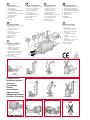 2
2
-
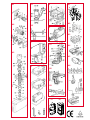 3
3
-
 4
4
-
 5
5
-
 6
6
-
 7
7
-
 8
8
-
 9
9
-
 10
10
-
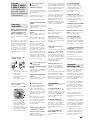 11
11
-
 12
12
-
 13
13
-
 14
14
-
 15
15
-
 16
16
-
 17
17
-
 18
18
-
 19
19
-
 20
20
-
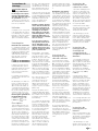 21
21
-
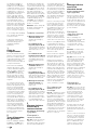 22
22
-
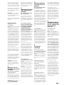 23
23
-
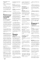 24
24
-
 25
25
-
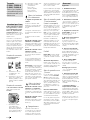 26
26
-
 27
27
-
 28
28
-
 29
29
-
 30
30
-
 31
31
-
 32
32
-
 33
33
-
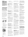 34
34
-
 35
35
-
 36
36
-
 37
37
-
 38
38
-
 39
39
-
 40
40
-
 41
41
-
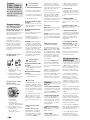 42
42
-
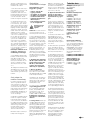 43
43
-
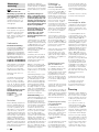 44
44
-
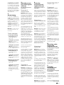 45
45
-
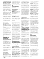 46
46
-
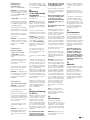 47
47
-
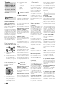 48
48
-
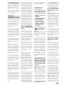 49
49
-
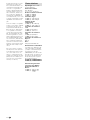 50
50
-
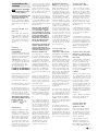 51
51
-
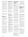 52
52
-
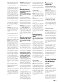 53
53
-
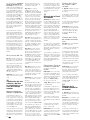 54
54
-
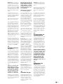 55
55
-
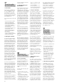 56
56
-
 57
57
-
 58
58
-
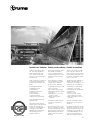 59
59
-
 60
60
-
 61
61
-
 62
62


Truma Trumatic E 4000 Operating Instructions Manual
- Type
- Operating Instructions Manual
- This manual is also suitable for
Ask a question and I''ll find the answer in the document
Finding information in a document is now easier with AI
in other languages
- italiano: Truma Trumatic E 4000
- français: Truma Trumatic E 4000
- español: Truma Trumatic E 4000
- Deutsch: Truma Trumatic E 4000
- Nederlands: Truma Trumatic E 4000
- dansk: Truma Trumatic E 4000
Related papers
-
Truma Trumatic E 4000 Operating instructions
-
-
-
-
-
-
-
-
Truma VarioHeat Installation Instructions Manual
-
Other documents
-
Trumatic S 5002 Installation Instructions Manual
-
-
Dometic RMDT8501, RMDT8505, RMDT8551, RMDT8555 Installation guide
-
Dometic RMDT8501, RMDT8505, RMDT8551, RMDT8555 Installation guide
-
Tristar KA-5340 User manual
-
-
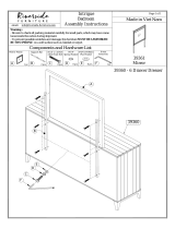 Riverside Furniture 39361 Assembly Instructions
-
-
-
