Garmin Embraer Prodigy 100 NXI Owner's manual
- Type
- Owner's manual

190-02545-02 June 2020 Revision 3
G1000 NXi
NXi updates to G1000 on Textron Aviation 510
System Maintenance Manual
EMBRAER
Phenom P100
Includes Instructions for Continued Airworthiness
for SA01933WI

Garmin G1000 NXi System Maintenance Manual 190-02545-02
Embraer Phenom P100 Revision 3
Page 1
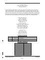
© Copyright 2020
Garmin Ltd. or its subsidiaries
All Rights Reserved
Except as expressly provided herein, no part of this manual may be reproduced, copied, transmitted,
disseminated, downloaded or stored in any storage medium, for any purpose without the express prior
written consent of Garmin. Garmin hereby grants permission to download a single copy of this manual
and of any revision to this manual onto a hard drive or other electronic storage medium to be viewed and
to print one copy of this manual or of any revision hereto, provided that such electronic or printed copy of
this manual or revision must contain the complete text of this copyright notice and provided further that
any unauthorized commercial distribution of this manual or any revision hereto is strictly prohibited.
Garmin International, Inc.
1200 E. 151st Street
Olathe, KS 66062 USA
Telephone: 913.397.8200
www.garmin.com
Garmin (Europe) Ltd.
Liberty House, Bulls Copse Road
Hounsdown Business Park
Southampton, SO40 9RB, UK
Phone: +44 (0) 23 8052 4000
Fax: +44 (0) 23 8052 4004
Garmin AT, Inc.
2345 Turner Rd., SE
Salem, OR 97302 USA
Telephone: 503.581.8101
RECORD OF REVISIONS
Revision
Revision Date
Description
1
10/29/19
Initial Release
2
11/5/19
Update enable card options on page 31
3
6/24/20
Revised 3.5.2, 3.6, 3.8.4. added 8.6
DOCUMENT PAGINATION
Section
Pagination
Table of Contents
3-5
Section 1
6-9
Section 2
10-18
Section 3
19-59
Section 4
60-66
Section 5
67-78
Section 6
79-88
Section 7
89-107
Section 8
108-121
Section 9
122-131
Appendix A
132

Garmin G1000 NXi System Maintenance Manual 190-02545-02
Embraer Phenom P100 Revision 3
Page 2
INFORMATION SUBJECT TO EXPORT CONTROL LAWS
This document may contain information which is subject to the Export Administration
Regulations (“EAR”) issued by the United States Department of Commerce (15 CFR, Chapter
VII Subchapter C) and which may not be exported, released or disclosed to foreign nationals
inside or outside the United States without first obtaining an export license. A violation of the
EAR may be subject to a penalty of up to 10 years imprisonment and a fine of up to $1,000,000
under section 2410 of the Export Administration Act of the 1979. The preceding statement is
required to be included on any and all reproductions in whole or in part of this manual.
WARNING
This product, its packaging, and its components contain chemicals known to the State of
California to cause cancer, birth defects, or reproductive harm. This Notice is being provided in
accordance with California's Proposition 65. If you have any questions or would like additional
information, please refer to our web site at www.garmin.com/prop65.
WARNING
Perchlorate Material – special handling may apply, Refer to www.dtsc.ca.gov./hazardouswaste/
perchlorate.
IMPORTANT
All screen shots used in this document are current at the time of publication. Screen shots are
intended to provide visual reference only. All information depicted in screen shots, including
software file names, versions and part numbers, is subject to change and may not be up to
date.

Garmin G1000 NXi System Maintenance Manual 190-02545-02
Embraer Phenom P100 Revision 3
Page 3
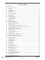
TABLE OF CONTENT
1. INTRODUCTION ............................................................................................................................................. 6
1.1 CONTENT, SCOPE, PURPOSE ................................................................................................................................ 6
1.2 APPLICABILITY .................................................................................................................................................. 6
1.3 ORGANIZATION ................................................................................................................................................. 6
1.4 DEFINITIONS/ABBREVIATIONS ............................................................................................................................. 7
1.5 UNITS OF MEASURE........................................................................................................................................... 7
1.6 PUBLICATIONS .................................................................................................................................................. 8
1.7 REVISION AND DISTRIBUTION .............................................................................................................................. 9
1.8 GARMIN TECHNICAL SUPPORT ............................................................................................................................. 9
2. SYSTEM DESCRIPTION ................................................................................................................................. 10
2.1 EQUIPMENT DESCRIPTIONS ............................................................................................................................... 10
2.2 SYSTEM INTERFACE SUMMARY ........................................................................................................................... 14
2.3 POWER REQUIREMENTS ................................................................................................................................... 15
2.4 ELECTRICAL BONDING ...................................................................................................................................... 15
3. CONTROL AND OPERATION ......................................................................................................................... 19
3.1 CONFIGURATION MODE OVERVIEW .................................................................................................................... 19
3.2 G1000 SYSTEM SOFTWARE INFORMATION .......................................................................................................... 25
3.3 CONFIGURATION MODE ................................................................................................................................... 26
3.4 G1000 HARDWARE/SOFTWARE COMPATIBILITY CHECK ......................................................................................... 26
3.5 EQUIPMENT VERIFICATION (THIRD PARTY/OPTIONAL EQUIPMENT DOCUMENTATION) ................................................. 27
3.6 CONFIGURATION CHECKLIST .............................................................................................................................. 31
3.7 G1000 SOFTWARE/CONFIGURATION PROCEDURE ................................................................................................ 32
3.8 SYSTEM SOFTWARE AND CONFIGURATION LOAD ................................................................................................... 33
3.9 FEATURE ENABLEMENT .................................................................................................................................... 50
3.10 CONFIGURATION MANAGER .............................................................................................................................. 54
3.11 CLEARING DEFAULT USER SETTINGS .................................................................................................................... 55
3.12 DATABASE LOADING ........................................................................................................................................ 55
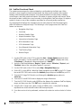
3.13 CONFIGURATION OF NAVIGATION MAP FOR TRAFFIC SYSTEM .................................................................................. 58
3.14 FLIGHT STREAM 510 FIRMWARE REVIEW ............................................................................................................ 58
4. INSTRUCTIONS FOR CONTINUED AIRWORTHINESS...................................................................................... 60
4.1 AIRWORTHINESS LIMITATIONS ........................................................................................................................... 60
4.2 SERVICING INFORMATION ................................................................................................................................. 60
4.3 MAINTENANCE INTERVALS ................................................................................................................................ 62
4.4 VISUAL INSPECTION ......................................................................................................................................... 64
4.5 ELECTRICAL BONDING TEST ............................................................................................................................... 65
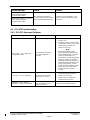
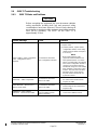
5. TROUBLESHOOTING .................................................................................................................................... 67
5.1 SYSTEM ANNUNCIATIONS ................................................................................................................................. 68
5.2 AURAL & AUDIO ALERTS .................................................................................................................................. 69
5.3 GDU 1250A TROUBLESHOOTING ...................................................................................................................... 69
5.4 GDU ALERTS ................................................................................................................................................. 70
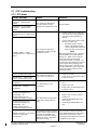
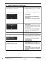
5.5 GMA 1360D TROUBLESHOOTING ..................................................................................................................... 71
5.6 GCU 475 TROUBLESHOOTING .......................................................................................................................... 72
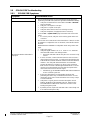
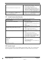
5.7 GTX TROUBLESHOOTING .................................................................................................................................. 73
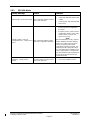
5.8 GDL69A SXM TROUBLESHOOTING ................................................................................................................... 74
5.9 GWX 75 TROUBLESHOOTING ........................................................................................................................... 76
5.10 SOFTWARE/CONFIGURATION TROUBLESHOOTING ................................................................................................. 77
5.11 SYSTEM COMMUNICATION HIERARCHY................................................................................................................ 78
5.12 CONNECTOR LAYOUT ....................................................................................................................................... 78
6. EQUIPMENT REMOVAL & INSTALLATION .................................................................................................... 79

Garmin G1000 NXi System Maintenance Manual 190-02545-02
Embraer Phenom P100 Revision 3
Page 4
6.1 GDU 1250A ................................................................................................................................................. 79
6.2 GMA 1360D AUDIO PANEL ............................................................................................................................. 79
6.3 GTX 345R / GTX 345DR TRANSPONDER........................................................................................................... 80
6.4 GCU 475 CONTROLLER ................................................................................................................................... 81
6.5 GWX 75 WEATHER RADAR .............................................................................................................................. 81
6.6 GDL 69A SXM RECEIVER ................................................................................................................................ 86
6.7 CONFIGURATION MODULES .............................................................................................................................. 87
7. GARMIN G1000 LRU REPLACEMENT/CONFIGURATION & TESTING .............................................................. 89
7.1 GIA BOOT BLOCK LOAD ................................................................................................................................... 89
7.2 .GDU 1250A DISPLAY .................................................................................................................................... 90
7.3 GMA 1360D AUDIO PANEL ............................................................................................................................. 93
7.4 GTX 345R / GTX 345DR TRANSPONDER........................................................................................................... 97
7.5 GCU 475 FMS CONTROLLER ......................................................................................................................... 100
7.6 GWX 75 WEATHER RADAR ............................................................................................................................ 103
8. SUBSYSTEM FUNCTIONAL CHECKS ............................................................................................................. 108
8.1 TAWS FUNCTIONAL CHECK ............................................................................................................................ 108
8.2 FLITECHARTS FUNCTIONAL CHECK .................................................................................................................... 110
8.3 CHARTVIEW FUNCTIONAL CHECK ..................................................................................................................... 111
8.4 SAFETAXI FUNCTIONAL CHECK ......................................................................................................................... 112
8.5 GTS 850 TRAFFIC SYSTEM FUNCTIONAL CHECK .................................................................................................. 113
8.6 TCAS 3000 TRAFFIC SYSTEM FUNCTIONAL CHECK .............................................................................................. 114
8.7 GWX 68 / 70 SYSTEM FUNCTIONAL CHECK ....................................................................................................... 115
8.8 DME FUNCTIONAL CHECK .............................................................................................................................. 116
8.9 ADF FUNCTIONAL CHECK ............................................................................................................................... 119
8.10 HF RADIO FUNCTION CHECK ........................................................................................................................... 119
8.11 RADIO ALTIMETER FUNCTION CHECK ................................................................................................................ 121
9. G1000 SYSTEM RETURN TO SERVICE PROCEDURE ..................................................................................... 122
9.1 DISPLAY TEST ............................................................................................................................................... 122
9.2 G1000 BACKUP PATH TEST ............................................................................................................................ 125
9.3 DISPLAY FAILURE TEST ................................................................................................................................... 125
9.4 REVERSION MODE CHECK ............................................................................................................................... 126
9.5 AIRCRAFT BASIC EMPTY WEIGHT INITIALIZATION ................................................................................................. 128
9.6 GPS SIGNAL ACQUISITION .............................................................................................................................. 129
9.7 FIELD ELEVATION INITIALIZATION ...................................................................................................................... 129
9.8 EICAS VERIFICATION ..................................................................................................................................... 130
9.9 TEST PANEL ................................................................................................................................................. 130
9.10 MAINTENANCE RECORDS ................................................................................................................................ 131
APPENDIX A - GARMIN UNIT PART AND SERIAL NUMBER CROSS REFERENCE .................................................... 132

Garmin G1000 NXi System Maintenance Manual 190-02545-02
Embraer Phenom P100 Revision 3
Page 5
TABLE OF FIGURES
FIGURE 2-1 – GCU 475 .................................................................................................................................................... 12
FIGURE 2-2 – GDU 1250A ............................................................................................................................................... 12
FIGURE 2-3 – GMA 1360D .............................................................................................................................................. 12
FIGURE 2-4 – GTX 345R .................................................................................................................................................. 12
FIGURE 2-5 – GTX 345DR ................................................................................................................................................ 12
FIGURE 2-6 – FS 510 ....................................................................................................................................................... 12
FIGURE 2-7 – GWX 75 ..................................................................................................................................................... 13
FIGURE 2-8 – GDL 69A SXM ............................................................................................................................................ 13
FIGURE 2-9 – G1000 NXI SYSTEM OVERVIEW ....................................................................................................................... 14
FIGURE 2-10 – ELECTRICAL BONDING PREPARATION – NUT PLATE ............................................................................................ 16
FIGURE 2-11 – ELECTRICAL BONDING PREPARATION – BOLT/NUT JOINT .................................................................................... 17
FIGURE 2-12 – ELECTRICAL BONDING PREPARATION – TERMINAL LUG ....................................................................................... 17
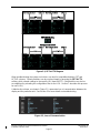
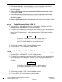
FIGURE 3-1, SET>ACTV DIAGRAM ..................................................................................................................................... 21
FIGURE 3-2, LOSS OF COMMUNICATION ............................................................................................................................... 21
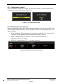
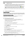
FIGURE 3-3, CONFIGURATION STATUS .................................................................................................................................. 22
FIGURE 3-4, DATA TRANSMISSION INDICATORS ...................................................................................................................... 22
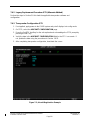
FIGURE 3-5, GARMIN UNIT S/N LOCATION ........................................................................................................................... 27
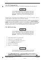
FIGURE 3-6, SOFTWARE/CONFIGURATION OVERVIEW ............................................................................................................. 32
FIGURE 3-7, MFD AUX – DATABASE PAGE DB TRANSFER (EXAMPLE) ........................................................................................ 57
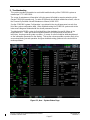
FIGURE 5-1, AUX – SYSTEM STATUS PAGE ............................................................................................................................ 67
FIGURE 5-2, SYSTEM ANNUNCIATIONS ................................................................................................................................. 68
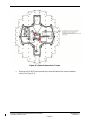
FIGURE 6-1, RADAR ANTENNA INNER SCREWS ....................................................................................................................... 82
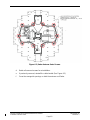
FIGURE 6-2, RADAR ANTENNA OUTER SCREWS. ..................................................................................................................... 83
FIGURE 6-3, CABLE BUNDLE POSITION ................................................................................................................................. 84
FIGURE 6-4, RADAR MOUNTING ADAPTERS .......................................................................................................................... 85
FIGURE 6-5, CONFIGURATION MODULE INSTALLATION ............................................................................................................ 87
FIGURE 7-1, G1000 NORMAL MODE CHECK ........................................................................................................................ 93
FIGURE 7-2, AIRCRAFT REGISTRATION EXAMPLE ..................................................................................................................... 98
FIGURE 9-1, MFD POWER UP PAGE .................................................................................................................................. 122
FIGURE 9-2, PFD POWER-UP SYSTEM ANNUNCIATIONS ........................................................................................................ 123
FIGURE 9-3, PFD NORMAL OPERATION ............................................................................................................................. 124
FIGURE 9-4, GDU REVERSIONARY MODE ........................................................................................................................... 127
FIGURE 9-5, BASIC EMPTY WEIGHT ENTRY .......................................................................................................................... 128
FIGURE 9-6, AUX-GPS STATUS PAGE ................................................................................................................................ 129

Garmin G1000 NXi System Maintenance Manual 190-02545-02
Embraer Phenom P100 Revision 3
Page 6
1. Introduction
1.1 Content, Scope, Purpose
This document provides maintenance instructions and Instructions for Continued Airworthiness
(ICA) for the changes to the G1000 Integrated Flight Deck as installed in the Embraer Model
EMB-500 Phenom P100. Throughout this document, this aircraft model will be referred to as
“Phenom 100”, unless otherwise specified. The change under STC SA01933WI upgrades the
system to the NXi configuration of the Garmin G1000 Integrated Flight Deck including the
GFC700 Automatic Flight Control System (AFCS). This document satisfies the requirements for
continued airworthiness as defined by 14 CFR Part 23.1529 and Appendix G. Information in
this document is required to maintain the continued airworthiness of the G1000 and GFC700.
Throughout this document, the GFC 700 autopilot system is included in the G1000NXi system
description and is identified separately only when needed.
1.2 Applicability
This document applies to Embraer Phenom 100 aircraft equipped with the G1000 NXi system.
All G1000NXi Phenom 100 aircraft are configured per General Arrangement drawing
005-01385-01, Rev 1 or subsequent approved revision.
Modification of an aircraft by Supplemental Type Certificate STC SA01933WI obligates the
aircraft operator to include the maintenance information provided by this document in the
operator’s Aircraft Maintenance Manual and the operator’s Aircraft Scheduled Maintenance
Program. The scope of maintenance information in this document is limited to aspects
pertaining to the Garmin G1000 NXi upgrade only. For other G1000 and aircraft level
maintenance items, refer to the Embraer Phenom 100 Maintenance Manual.
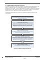
1.3 Organization
The following outline briefly describes the organization of this manual:
Section 2: System Description
Provides a complete description of the type design change associated with installing the G1000
NXi on Embraer Phenom 100 aircraft. Also provides an interface summary, power
requirements, and instructions on electrical bonding.
Section 3: Control and Operation
Provides brief instructions on controls and operation of the G1000 NXi system.
Section 4: Instructions for Continued Airworthiness
Provides maintenance procedures and instructions for continued airworthiness of the G1000
NXi system.
Section 5: Troubleshooting
Provides troubleshooting information to aid in diagnosing and resolving potential problems with
G1000 NXi system.
Section 6: Equipment Removal & Replacement
Gives instructions for the removal and replacement of G1000 NXi equipment.
Section 7: LRU Configuration & Testing
Gives instructions for loading software, configuring, and testing of the G1000 NXi system.
Section 8: Sub-System Functional Checks
Gives instructions for loading software and configuring the G1000 NXi system.

Garmin G1000 NXi System Maintenance Manual 190-02545-02
Embraer Phenom P100 Revision 3
Page 7
Section 9: G1000 System Return to Service Procedures
Specifies return-to-service procedures to be performed upon completion of maintenance of the
G1000 NXi system.
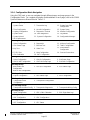
1.4 Definitions/Abbreviations
ADI: Attitude Director Indicator
AML: Approved Model List
ARP: Aerospace Recommended Practice
ASTM: American Society for Testing and Materials
CDI: Course Deviation Indicator
CFR: Code of Federal Regulations
CWS: Control Wheel Steering
DDM: Difference in Depth of Modulation
DTK: Desired Track
FAA: Federal Aviation Administration
GPS: Global Positioning System
ICA: Instructions for Continued Airworthiness
ILS: Instrument Landing System
LRU: Line Replaceable Unit
MFD: Multifunction Flight Display
n/a: Not Applicable
NXi: Next Generation Integrated
OBS: Omni-Bearing Selector
PED: Personal Electronic Device
PFD: Primary Flight Display
PFT: Pre-Flight Test
SAE: Society of Automotive Engineers
SD: Secure Digital
SXM: SiriusXM
STC: Supplemental Type Certificate
VOR: VHF Omnidirectional Radio
1.5 Units of Measure
Unless otherwise stated, all units of measure are English units.

Garmin G1000 NXi System Maintenance Manual 190-02545-02
Embraer Phenom P100 Revision 3
Page 8
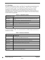
1.6 Publications
All Garmin documents listed in Table 1-1 and Table 1-2 are available for download through the
Dealer Resource Center section of the Garmin web site. Refer to Section 1.7 for details.
The documents listed in Table 1-1 are required by this maintenance manual to perform
maintenance on the G1000 NXi system on the Embraer Phenom 100 aircraft. It is the
responsibility of the owner/operator to ensure that the latest versions of these documents are
used during operation, servicing or maintenance of the airplane. Refer to the Master Drawing
List 005-01385-00 for applicability.
Table 1-1 – Required Documents
GARMIN PUBLICATIONS
Document Number
Document Title
005-01385-00
Master Drawing List Embraer Phenom Garmin G1000 Integrated Avionics System
Updates
005-01385-01
General Arrangement, G1000 NXi, Embraer Phenom P100
005-01385-19
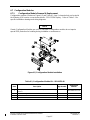
Equipment Installation, Phenom 100 NXi Upgrade
005-01385-18
Wire Harness Routing/Install Embraer Phenom P100
005-W0042-00
Wiring Diagram, G1000 NXi, Embraer Phenom P100
EMBRAER PUBLICATIONS
AMM-2432
Phenom By Embraer Aircraft Maintenance Manual
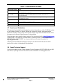
The documents listed in Table 1-2 are recommended to be available during the performance of
maintenance activities.
Table 1-2 –Reference Publications
GARMIN PUBLICATIONS
Document Number
Document Title
190-02545-01
Airplane Flight Manual Supplement, G1000 Integrated Avionics System and GFC 700
AFCS in Embraer Model EMB-500 (Phenom 100)
190-02547-00
Prodigy Nxi Flight Deck 100 Cockpit Reference Guide Embraer Phenom 100
190-02546-00
Prodigy Nxi Flight Deck 100 Pilot's Guide Embraer Phenom 100
190-00355-04
GDL 69 Series SiriusXM Satellite Radio Activation Instructions
190-00903-00
G1000 System Maintenance Manual (LJ/VLJ Aircraft)
190-00303-93
GDU 1250A Installation Manual
190-03813-00
GMA 1360 Installation Manual
190-01499-02
GTX 3X5 Transponder TSO Installation Manual
190-02009-00
GWX Processor Installation Manual.
190-00355-07
GDL 69 Series TSO Installation Manual

Garmin G1000 NXi System Maintenance Manual 190-02545-02
Embraer Phenom P100 Revision 3
Page 9
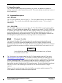
Table 1-3 – Other Reference Documents
Document Number
Title
AC 43.13-1B
FAA Advisory Circular, Acceptable Methods, Techniques, and Practices
– Aircraft Inspection and Repair
AC 43.13-2B
FAA Advisory Circular, Acceptable Methods, Techniques, and Practices
– Aircraft Alterations
SAE ARP1870
Aerospace Systems Electrical Bonding and Grounding for Electromagnetic
Compatibility and Safety
SAE AS4461
Assembly and Soldering Criteria for High Quality/High Reliability Soldered Wire and
Cable Termination in Aerospace Vehicles
SAE AS50881
Wiring, Aerospace Vehicle
ASTM F 2490-05
Standard Guide for Aircraft Electrical Load and Power Source Capacity Analysis
1.7 Revision and Distribution
This document is required for maintaining the continued airworthiness of the G1000 NXi system
on the Embraer Phenom 100 aircraft. When this document is revised, every page will be
updated to indicate current revision level. Garmin Dealers may obtain the latest revision of this
document on the Garmin Dealer Resource Center website.
Owner/operators may obtain the latest revision of this document from the https://fly.garmin.com
Support page, or by contacting a Garmin dealer, contacting Garmin Product Support at 913-
397-8200, toll free 866-739-5687, or using around the world contact information on
https://fly.garmin.com/.
A Garmin Service Bulletin describing the revision to this document will be sent to Garmin
dealers if the revision is determined to be significant.
1.8 Garmin Technical Support
For technical support contact, Garmin Aviation Product Support at 913-397-8200 (toll free 866-
739-5687) or by using the around-the-world contact information on www.flygarmin.com.

Garmin G1000 NXi System Maintenance Manual 190-02545-02
Embraer Phenom P100 Revision 3
Page 10
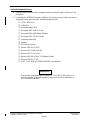
2. System Description
The G1000 NXi system components described in this section are additions or updates to
existing components on the Embraer Phenom 100. This section briefly describes the function of
these components.
2.1 Equipment Descriptions
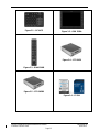
2.1.1 GCU 475
The GCU 475 controller is shown in Figure 2-1. This is an updated version of the existing GCU
475 controller. The controller is updated with improved joystick function. This is a drop-in
replacement.
2.1.2 GDU 1250A
The GDU 1250A display unit is shown in Figure 2-2. The GDU 1250A is used as primary flight
displays (PFDs) and multifunction display (MFD), mounted in the cockpit. The GDU 1250As are
an update to the existing GDU 1240As that were originally installed. The new displays have the
same overall dimensions as the previous generation hardware, with physical controls and
labeling being identical to the previous versions. The new GDU 1250A displays contain a new
LED backlight, and updated electronics, including a multi-core microprocessor.
Electronic Checklist
The Electronic Checklists (ECL) function allows the user to view and interact with aircraft
checklists. The Checklist contents are displayed on the GDUs and the checklist control is
performed using the GCU 475. The Garmin Checkset tool is provided by Garmin at no charge to
the aircraft operator to generate and edit the custom checklist files which are saved in the .gcl
format.
NOTE
For the G1000 NXi update, the checklist has to be saved as a “.gcl” file for
the checklist function to work.
The Checkset tool can be downloaded from the Fly.Garmin website under the Tools menu
(https://fly.garmin.com/fly-garmin/). The checklist is created or edited by the OEM/End user
without involvement from Garmin. Once the electronic checklist is created by the OEM/end user,
it is then downloaded onto an SD card and inserted into the top or bottom MFD card slot. Upon
power-up, the G1000 system checks the MFD SD cards for any checklist files and then
transfers the electronic checklist to the GDU internal memory. Once the Checklist is transferred
to the GDU, the SD card containing the checklist files can be removed and is no longer
required.
Please note that operational usage of the checklist file may require regulatory approval. The
OEM/Operator is expected to obtain the required approval.

Garmin G1000 NXi System Maintenance Manual 190-02545-02
Embraer Phenom P100 Revision 3
Page 11
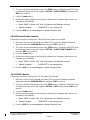
2.1.3 GMA 1360D (optional)
The GMA 1360D audio panel is shown in Figure 2-3. This unit replaces the GMA 1347D audio
panel and there are two per aircraft. The GMA 1360D brings 3D audio and Bluetooth
connectivity.
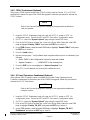
2.1.4 GTX 345R (optional)
The GTX 345R transponder is shown in Figure 2-4. The GTX 345R replaces the existing #1
GTX 33 w/ES Mode S transponder with a GTX 345R ADS-B transponder when there is only one
transponder on the aircraft, or when a GTX 33DR is in the #2 transponder position. The GTX
345R provides ADS-B Out. The GTX 345R also provides ADS-B In for TIS-B and air-to-air
traffic and FIS-B weather data to the G1000 NXi system for display to the flight crew.
2.1.5 GTX 345DR (optional)
The GTX 345DR transponder is shown in Figure 2-5. The GTX 345DR replaces the existing #2
GTX 33D w/ES Mode S transponder (if installed) with a GTX 345DR ADS-B transponder when
there is a GTX 33 in the #1 transponder position. The GTX 345DR is a dual-link diversity ADS-
B In receiver, capable of receiving 1090 MHz and 978 MHz Universal Access Transceiver (UAT)
data. The GTX 345DR’s datalink provides traffic (TIS-B and air-to-air) and weather (FIS-B) data
for display on the PFD’s and MFD.
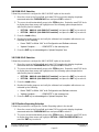
2.1.6 FS 510
The FS 510 (Flight Stream 510) wireless data card is shown in Figure 2-6. The FS 510 is an
SD card that installs into the MFD in the aircraft cockpit. The FS510 offers the addition of Wi-Fi
and Bluetooth connectivity for activities such as flight plan transfers and data output to carry-on
devices such as tablets and electronic flight bags. This data may be in the form of GPS
information, weather, aircraft traffic, or other items for flight crew use.
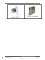
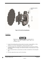
2.1.7 GWX 75 (Optional)
The optional GWX 75 weather radar is shown in Figure 2-7. The GWX 75 replaces the existing
weather radar and provides turbulence detection and ground clutter suppression, not available
with the GWX 68.
2.1.8 GDL 69A SXM (Optional)
The optional GDL 69A SXM receiver is shown in Figure 2-8. The GDL 69A SXM replaces the
existing GDL 69 XM receiver and is required if either optional GTX 345R or a GTX 345DR
transponder is installed in the aircraft. The GDL 69A SXM unit provides the same functions and
interfaces as the legacy GDL 69A it replaces and is designed to be compatible with the updated
SiriusXM G4 satellite network.

Garmin G1000 NXi System Maintenance Manual 190-02545-02
Embraer Phenom P100 Revision 3
Page 12
Figure 2-1 – GCU 475
Figure 2-2 – GDU 1250A
Figure 2-3 – GMA 1360D
Figure 2-4 – GTX 345R
Figure 2-5 – GTX 345DR
Figure 2-6 – FS 510

Garmin G1000 NXi System Maintenance Manual 190-02545-02
Embraer Phenom P100 Revision 3
Page 13
Figure 2-7 – GWX 75
Figure 2-8 – GDL 69A SXM

Garmin G1000 NXi System Maintenance Manual 190-02545-02
Embraer Phenom P100 Revision 3
Page 14
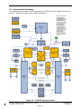
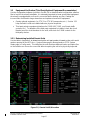
2.2 System Interface Summary
The following figure provides a high-level summary of G1000 NXi on the Embraer Phenom 100.
Aircraft. Yellow blocks signify new or updated equipment.
Figure 2-9 – G1000 Nxi System Overview

Garmin G1000 NXi System Maintenance Manual 190-02545-02
Embraer Phenom P100 Revision 3
Page 15
2.3 Electrical Load Requirements
Table 2-1 below summarizes the electrical load requirements for the LRUs installed by this STC.
Table 2-1 – Electrical Load Requirements
LRU
Characteristics
Specifications
Notes
GCU 475
Max Current Draw @ 28 VDC
0.05 A
GDU 1250A
Max Current Draw @ 28 VDC
0.9 A
At or below -15° = 1.9A
GMA 1360D
Max Current Draw @ 28 VDC
1.00 A
GTX 345R
Max Current Draw @ 28 VDC
0.65 A
GTX 345DR
Max Current Draw @ 28 VDC
0.65 A
FS 510
Max Current Draw @ 28 VDC
n/a
Powered by GDU 1250A
GWX 75
Max Current Draw @ 28 VDC
2.5 Amps
GDL 69A
Max Current Draw @ 28 VDC
0.35 Amps
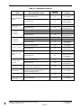
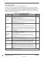
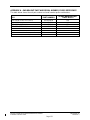
2.4 Electrical Bonding
For the purposes of this STC, aircraft ground reference definitions vary according to airframe
type, as defined in Table 2-2. Refer to the periodic test and reconditioned resistance values
corresponding to these ground reference definitions when performing the equipment bonding
tests in Section 4.5.
The periodic test value is the value allowed during the bonding checks specified in Section 4.5.
The reconditioned value is the value allowed on initial installation or if the bond must be
reworked if the periodic test value is exceeded.
Refer to SAE ARP 1870 Section 5 when surface preparation is required to achieve electrical
bond.
NOTE
Bonding checks are performed with harness connectors connected for all
equipment except for the GWX 75 (If installed). GWX 75 bonding checks
are to be accomplished with the harness connectors disconnected.

Garmin G1000 NXi System Maintenance Manual 190-02545-02
Embraer Phenom P100 Revision 3
Page 16
Table 2-2 – Electrical Bonding
Aircraft Type
Ground Reference
Maximum Resistance Between LRU
Equipment Chassis and Ground
Reference (mΩ)
Periodic Test
Reconditioned
Metallic Airframe
Nearby metal structure
or
Instrument panel for LRU
30.0 for PFD1,
MFD, PFD2, GCU,
or GMA 1360D (if
installed)
20.0 for PFD1,
MFD, PFD2, GCU,
or GMA 1360D (if
installed)
5.0 for GTX 345R
(if installed),
GDL69A SXM (if
installed), or GWX
75 (if installed)
2.5 for GTX 345R
(if installed),
GDL69A SXM (if
installed), or GWX
75 (if installed)
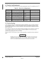
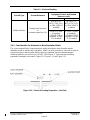
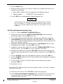
2.4.1 Consideration for Untreated or Bare Dissimilar Metals
The correct material finish is important when mating untreated or bare dissimilar metals.
Materials should be galvanically compatible. When corrosion protection is removed to make an
electrical bond any exposed area after the bond is completed should be protected again.
Additional guidance can be found in SAE ARP 1870 Section 5. Typical electrical bonding
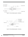
preparation examples are shown in Figure 2-10, Figure 2-11, and Figure 2-12.
Figure 2-10 – Electrical Bonding Preparation – Nut Plate

Garmin G1000 NXi System Maintenance Manual 190-02545-02
Embraer Phenom P100 Revision 3
Page 17
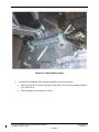
Figure 2-11 – Electrical Bonding Preparation – Bolt/Nut Joint
Figure 2-12 – Electrical Bonding Preparation – Terminal Lug

Garmin G1000 NXi System Maintenance Manual 190-02545-02
Embraer Phenom P100 Revision 3
Page 18
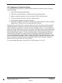
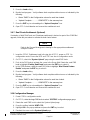
2.4.2 Preparation of Aluminum Surfaces
The following general procedure is recommended to prepare an aluminum surface for proper
electrical bonding.
1. Clean grounding location with solvent.
2. Remove non-conductive films or coatings from the grounding location.
3. Apply a chemical conversion coat such as Alodine 1200 to the bare metal.
4. Once the chemical conversion coat is dry, clean the area.
5. Install bonding equipment at grounding location.
6. After bond is complete, if any films or coatings were removed from the surface, reapply a
suitable film or coating to the surrounding area within 24 hours.
After satisfactory electrical bond is achieved, when it has been necessary to remove any high-
resistance protective coating, the area from which the coating has been removed should be
refinished with the same finish as is on the rest of the part within 24 hours. In cases where the
parts come in with certain areas spot-faced, or if there is no finish on the part (bare metal), apply
conformal coating over the bond joint and hardware per MIL-I-46058 or clear lacquer per TT-L-
20A to facilitate future inspection. Refer to the model specific Aircraft Maintenance Manual or
Standard Practices Manual for surface protection requirements applicable to affected areas.
The correct material finish is important when mating untreated or bare dissimilar metals. They
should be galvanically compatible. When corrosion protection is removed to make an electrical
bond, any exposed area after the bond is completed should be protected again. Additional
guidance can be found in SAE ARP 1870 Section 5.
For a more detailed procedure, refer to SAE ARP 1870 Sections 5.1 and 5.5.

Garmin G1000 NXi System Maintenance Manual 190-02545-02
Embraer Phenom P100 Revision 3
Page 19
3. Control and Operation
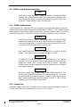
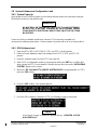
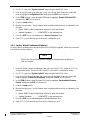
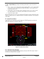
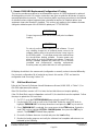
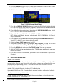
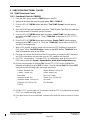
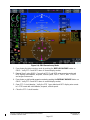
3.1 Configuration Mode Overview
Throughout this document, references are made to the PFD1, PFD2, and/or MFD being in
configuration mode. The configuration mode exists to provide the avionics technician with a
means of configuring, checking, and calibrating various G1000 Nxi sub-systems.
Troubleshooting and diagnostics information can be viewed in this mode.
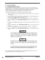
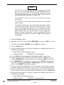
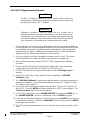
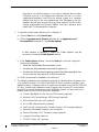
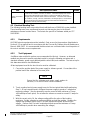
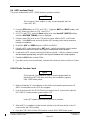
To start the G1000 Nxi system in configuration mode, follow these steps;
1. With the G1000 Nxi system off, open the MFD PWR 1, MFD PWR 2, PFD 1 and PFD 2
circuit breakers.
2. In accordance with AFM electrical system recommendation, connect external power to
the aircraft and energize the battery electrical busses.
3. Press and hold the ENT key on PFD 2 (copilot) and close the PFD 2 circuit breaker.
4. Release the ENT key after ‘INITIALIZING SYSTEM’ appears in the upper left corner of
PFD 2.
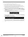
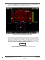
5. Press and hold the #12 (far right) softkey on the MFD and close the MFD PWR 1 circuit
breaker.
6. Release the #12 softkey after ‘INITIALIZING SYSTEM’ appears in the upper left corner
of MFD.
7. Press and hold the ENT key on PFD 1 (pilot) and close the PFD 1 circuit breaker.
8. Release the ENT key after ‘INITIALIZING SYSTEM’ appears in the upper left corner of
PFD 1.
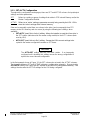
IMPORTANT
The Configuration Mode contains certain pages and settings that are
critical to aircraft operation and safety. These pages are protected and
cannot be modified unless the technician is properly authorized and
equipped. Most protected page content is viewable to allow system
awareness for troubleshooting.
NOTE
If the specific procedure requires an SD card to be in the top slot of the
PFD/MFD, this card must be inserted prior to applying power to the
PFD/MFD. Any time a card is inserted, the power to the PFD/MFD must
be cycled.
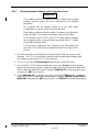
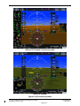
If a software loader card is inserted in the top slot of the display before it is
powered on, the display will automatically enter configuration mode and the
technician does not need to press and hold a softkey at power-on.
For a complete description and breakdown of each Configuration Mode page, refer to the
G1000 System Maintenance Manual listed in Table 1-2.
Page is loading ...
Page is loading ...
Page is loading ...
Page is loading ...
Page is loading ...
Page is loading ...
Page is loading ...
Page is loading ...
Page is loading ...
Page is loading ...
Page is loading ...
Page is loading ...
Page is loading ...
Page is loading ...
Page is loading ...
Page is loading ...
Page is loading ...
Page is loading ...
Page is loading ...
Page is loading ...
Page is loading ...
Page is loading ...
Page is loading ...
Page is loading ...
Page is loading ...
Page is loading ...
Page is loading ...
Page is loading ...
Page is loading ...
Page is loading ...
Page is loading ...
Page is loading ...
Page is loading ...
Page is loading ...
Page is loading ...
Page is loading ...
Page is loading ...
Page is loading ...
Page is loading ...
Page is loading ...
Page is loading ...
Page is loading ...
Page is loading ...
Page is loading ...
Page is loading ...
Page is loading ...
Page is loading ...
Page is loading ...
Page is loading ...
Page is loading ...
Page is loading ...
Page is loading ...
Page is loading ...
Page is loading ...
Page is loading ...
Page is loading ...
Page is loading ...
Page is loading ...
Page is loading ...
Page is loading ...
Page is loading ...
Page is loading ...
Page is loading ...
Page is loading ...
Page is loading ...
Page is loading ...
Page is loading ...
Page is loading ...
Page is loading ...
Page is loading ...
Page is loading ...
Page is loading ...
Page is loading ...
Page is loading ...
Page is loading ...
Page is loading ...
Page is loading ...
Page is loading ...
Page is loading ...
Page is loading ...
Page is loading ...
Page is loading ...
Page is loading ...
Page is loading ...
Page is loading ...
Page is loading ...
Page is loading ...
Page is loading ...
Page is loading ...
Page is loading ...
Page is loading ...
Page is loading ...
Page is loading ...
Page is loading ...
Page is loading ...
Page is loading ...
Page is loading ...
Page is loading ...
Page is loading ...
Page is loading ...
Page is loading ...
Page is loading ...
Page is loading ...
Page is loading ...
Page is loading ...
Page is loading ...
Page is loading ...
Page is loading ...
Page is loading ...
Page is loading ...
Page is loading ...
Page is loading ...
Page is loading ...
-
 1
1
-
 2
2
-
 3
3
-
 4
4
-
 5
5
-
 6
6
-
 7
7
-
 8
8
-
 9
9
-
 10
10
-
 11
11
-
 12
12
-
 13
13
-
 14
14
-
 15
15
-
 16
16
-
 17
17
-
 18
18
-
 19
19
-
 20
20
-
 21
21
-
 22
22
-
 23
23
-
 24
24
-
 25
25
-
 26
26
-
 27
27
-
 28
28
-
 29
29
-
 30
30
-
 31
31
-
 32
32
-
 33
33
-
 34
34
-
 35
35
-
 36
36
-
 37
37
-
 38
38
-
 39
39
-
 40
40
-
 41
41
-
 42
42
-
 43
43
-
 44
44
-
 45
45
-
 46
46
-
 47
47
-
 48
48
-
 49
49
-
 50
50
-
 51
51
-
 52
52
-
 53
53
-
 54
54
-
 55
55
-
 56
56
-
 57
57
-
 58
58
-
 59
59
-
 60
60
-
 61
61
-
 62
62
-
 63
63
-
 64
64
-
 65
65
-
 66
66
-
 67
67
-
 68
68
-
 69
69
-
 70
70
-
 71
71
-
 72
72
-
 73
73
-
 74
74
-
 75
75
-
 76
76
-
 77
77
-
 78
78
-
 79
79
-
 80
80
-
 81
81
-
 82
82
-
 83
83
-
 84
84
-
 85
85
-
 86
86
-
 87
87
-
 88
88
-
 89
89
-
 90
90
-
 91
91
-
 92
92
-
 93
93
-
 94
94
-
 95
95
-
 96
96
-
 97
97
-
 98
98
-
 99
99
-
 100
100
-
 101
101
-
 102
102
-
 103
103
-
 104
104
-
 105
105
-
 106
106
-
 107
107
-
 108
108
-
 109
109
-
 110
110
-
 111
111
-
 112
112
-
 113
113
-
 114
114
-
 115
115
-
 116
116
-
 117
117
-
 118
118
-
 119
119
-
 120
120
-
 121
121
-
 122
122
-
 123
123
-
 124
124
-
 125
125
-
 126
126
-
 127
127
-
 128
128
-
 129
129
-
 130
130
-
 131
131
-
 132
132
-
 133
133


Garmin Embraer Prodigy 100 NXI Owner's manual
- Type
- Owner's manual
Ask a question and I''ll find the answer in the document
Finding information in a document is now easier with AI
Related papers
-
Garmin Embraer Prodigy 100 NXI Owner's manual
-
-
-
-
-
-
Garmin GTX 345R Reference guide
-
-
-
Other documents
-
AG Neovo FMS-01 User manual
-
BOMBARDIER Challenger Global 300 User manual
-
Garmin International IPH-0060200 User manual
-
Virtual Fly VF-G1000 Desktop Trainer User manual
-
Pulse PFD-2000 Series User manual
-
GE 120V Installation guide
-
Sirius Satellite Radio SiriusXM Aviation Receiver Quick start guide
-
-
Viavi IFR 6000 Operating instructions
-
Control4 AN-X00-AP-X-AC Operating instructions