Page is loading ...


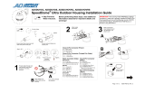
INSTALLATION:
To Open Housing:
• To open the housing, release the four tamper-resistance
screws located at the rear of the housing. (using supplied
4 mm allen wrench).
• Slide the outer housing forward until it reaches the fold-
down position (If you want to remove the outer housing
from the mount, rotate the outer housing 90 degrees to the
side).
To Mount the Housing:
• The 1335/1337 mounting hardware is shipped inside the
housing. To open the housing, see above.
• To mount the housing, slide the head of the two 6 mm bolts
(supplied) into the slide rail located on the bottom of the
housing.
• Position the holes in the slide rail to line-up holes in the
mounting surface.
• Secure housing with supplied washers and 6 mm nuts.
Camera Installation:
• Mount lens to camera body.
• Remove adjustable camera slide from housing (2 mm allen
wrench).
• Mount the camera assembly to the slide using 1/4"-20 bolt
and tighten.
• Install the camera into the housing selecting the proper
slide height in order to center the lens in housing window.
• Tighten the camera slide (2 mm allen wrench) to prevent
movement of the camera during operation.
Wiring Installation:
• Route cables through rear of housing using the two com-
pressing cable entries.
• Tighten compression fittings to insure proper weatherproof
condition.
HEATER ASSEMBLY:
Mounting Instructions:
• Wire thermostat to terminal block after removing jumper.
• Mount the heater element into the front channel on the
housing.
• Plug the heater assembly into the terminal block.
• Mount the terminal block to the rear of the housing (use the
screws supplied).
• The terminal block is designed to distribute main power to
camera and heater. CAUTION: Make sure supply voltage
and equipment voltages are compatible.
SUPPLY VOLTAGE:
20 VA- Heater Assembly
15 VA- Camera Assembly
* * * * * * * *
Thermostat
Camera
Main
Ground
Mounting Holes
Heater
HEATER
FRONT VIEW
HOUSING

Specifications
Mechanical Characteristics
Operating Environment: Indoor/Outdoor
Construction: Aluminum
Finish: 1315 - Light beige powder coat enamel
1317 - Natural aluminum finish
Model Standard w/ sunshield
Weight: 1335/14 7.55 lb (3.4 Kg) 10.5 lb (4.87 Kg)
1337/14
1335/18 _____ 12.0 lb (5.4 Kg)
1337/18
Cable Entry: Three, weatherproof glands
Window: Size - 3.5"W x 2.75"H (89 x 70 mm) Construction: 1/4" plate glass
Camera: Mounting - Non metallic mounting plate with four levels of height and full front to back adjustment
Heater: Type: PTC, automatic regulation
Voltage: 24VAC/VDC (12-30V)
Power Consumption: 1.0 A (maximum)
Weight: 0.15 lb (0.68 kg)
Environmental Characteristics
Weatherproof Standard: NEMA 4 (IP 65)
Other Models:
Deluxe:
1335/14 Weatherproof/dustproof housing with light beige powder coat enamel finish.
Supplied in 14 inch lengths.
1335/14S Same as above with sunshield
1335/14SH24 Same as above with sunshield and 24 volt heater installed
1335/18SH24 (120 V heaters can be substituted for 24V heater by specifying 120 in the housing model
number, i.e., 1335/14SH120.)
General Purpose:
1337/14 Weatherproof/dustproof housing with
natural aluminum finish. Supplied in
14 inch lengths
1337/14S Same as above with sunshield
1337/14SH24 Same as above with sunshield and 24 volt heater installed
1337/18SH24 (120 V heaters can be substituted for 24V heater by specifying 120 in the housing model
number, i.e., 1337/14SH120.)
An American Dynamics Product
Designed and built by
Sensormatic CCTV Systems Division
One Blue Hill Plaza
Pearl River, New York, 10965
(914) 624-7600
Technical Support Center: 1-800-442-2225
FAX: 914-624-7685
OP1335/ 1337A August 1993
/


