User’s Information Manual
15
Part Number 550-110-592/0709
• Donottrytolightanyappliance.
• Donottouchanyelectricswitch;donotuseanyphonein
your building.
• Immediatelycallyourgassupplierfromaneighbor’sphone.
Follow the gas supplier’s instructions.
• If you cannot reach your gas supplier, call the fire
department.
1. STOP! Read the safety information above on this label.
2. Set the thermostat to lowest setting.
3. Turn off all electrical power to the appliance.
4. Remove front panel.
5. Depress gas control knob slightly and turn clockwise
to “OFF”. Note:Gascontrolknobcannotbeturnedto
“OFF” unless knob is depressed slightly. Do not force.
1. Set the thermostat to lowest setting.
2. Turn off all electric power to the appliance if service is to
be performed.
3. Remove front panel.
4. Depress gas control knob slightly and turn clockwise
to “OFF”.
5. Replace front panel.
6. Wait five (5) minutes to clear out any gas. Then smell for
gas, including near the floor. If you smell gas,
STOP!
Follow “B” in the safety information above.
If you don’t smell gas, go to the next step.
7. Remove access panel located above burners.
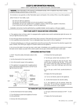
8. Findpilot—followmetaltubefromgascon-
trol. The pilot is between two burners behind
the access panel.
Lighting instructions
• Standing pilot
• Gas valve — Robertshaw 7000ERHC
A. This appliance has a pilot, which must be lighted
by hand. When lighting the pilot, follow these
instructions exactly.
B. BEFORE LIGHTING, smell all around the
appliance area for gas. Be sure to smell next to the
floor because some gas is heavier than air and will
settle on the floor. See below.
C. Useonlyyourhandtodepressorturnthegascontrolknob.Never
use tools. If the selector arm will not depress or move by hand, don’t
try to repair it, call a qualified service technician. Force or attempted
repair may result in a fire or explosion.
D. Do not use this appliance if any part has been under water.
Immediately call a qualified service technician to inspect the appliance
and to replace any part of the control system and any gas control,
which has been under water.
EG-75, EGH-85, EGH-95,
PFG-6, PFG-7
9. Turn gas control knob counterclockwise to “PILOT”.
10. Depress gas control knob and hold. Immediately light the
pilotwithamatch.Continuetoholdgascontrolknobin
for about one (1) minute after the pilot is lit.
• Ifpilotcanbelitwithoutdepressinggascontrolknob,
turn gas knob clockwise to “OFF” and call your
service technician or gas supplier.
11.Releasegascontrolknob.Pilotshouldremainlit.Ifpilot
goes out, repeat steps 5 through 11.
• Ifgascontrolknobstaysdepressedafterrelease,stop
and immediately call your service technician or gas
supplier.
• Ifthepilotwillnotstaylitafterseveraltries,turnthe
gas control knob clockwise to “OFF” and call
your service technician or gas supplier.
12. Replace access panel.
13. Turn gas control knob counterclockwise to “ON”.
14. Turn on all electric power to the appliance.
15. Set thermostat to desired setting.
16. Replace front panel.
550-223-081(0609)
FOR YOUR SAFETY READ BEFORE LIGHTING
LIGHTING INSTRUCTIONS
If you do not follow these instructions exactly, a fire or explosion may result
causing property damage, personal injury or loss of life.
WHAT TO DO IF YOU SMELL GAS
TO TURN OFF GAS TO THE APPLIANCE