Page is loading ...

Traceable
®
is a registered trademark of Control Company ©2009 Control Company. 92-4375-00 Rev. 2 060509
INFRARED THERMOMETER SPECIFICATION
Ranges: –4 to 752°F (–20 to 400°C)
Resolution: 0.1°C/0.1°F
Accuracy: ±3% of reading or ±3°C (5°F), whichever is greater.
Emissivity Setting:
* By push button. Setting range: 0.20 to 1.00.
* The default emissivity value is 0.95, which will cover 90% of a typical application.
Field of View: 7:1
TYPE K THERMOMETER SPECIFICATION
Ranges: –148.0 to 2372.0°F (–100.0 to 1300.0°C)
Resolution: 0.1°C/0.1°F
Accuracy: ±(1% + 2°F) or ± (1% + 1°C)
Sampling Time: Approx. 1 second.
Hold Function: To freeze the display reading value.
Memory Recall: Memorize the Maximum, Minimum reading with recall.
Offset Adjustment: Available for thermocouple thermometer offset adjustment by pushing button
on front panel.
Over Indication: Show “— — — —”.
Data Output: RS232 PC serial interlace.
Power Supply: Alkaline or heavy duty type, DC 9V battery, 006P, MN1604 ( PP3) or
equivalent.
Power
Consumption: Approx. DC 12 mA (w/o laser target light on). Approx. DC 18 mA (with laser
target light on). *Above consumption value is calculated under the function of
IR thermometer.
Size: 7¾ x 4¾ x 2¼ inches
Weight: 9 ounces
FEATURES
●
2 in 1, Infrared thermometer + Type K thermometer.
●
Microcomputer circuit with high performance.
●
Wide temperature measuring range.
●
Build in °C & °F select button on the front panel.
●
Data hold function for stored the desired value on display.
●
Memory function to record the maximum & minimum reading with recall.
●
Build the REL button, useful for relative measurement.
●
Sensor select button on the front panel, easy to change different type probe.
●
Infrared thermometer, non-contact temperature measurement, –20°C to 400°C
( –4 to 752°F).
●
0.1°C display resolution both for the measurement of IR thermometer and Type K
thermometer.
●
Emissivity adjustment for IR thermometer.
●
Laser target guide for IR thermometer.
●
Computer output, easy cooperate with computer.
●
Optional data acquisition software for data record.
●
Auto power shut off saves battery life.
●
Built—in low battery indicator.
●
Heavy duty & compact housing case with stand.
●
Operates from 006P DC 9V battery.
Front Panel Description
3-1. Display
3-2 °C/°F Button (Up Button)
3-3 Emissivity Button
3-4 Rel. Button
3-5 Rec. Button
3-6 Hold Button
3-7 Sensor Button
3-8 RS232 Output Socket
3-9 IR Sensing Head
3-10 Laser target Light Guide
3-11 Type K Input Socket
3-12 Laser Switch
3-13 Battery Compartment
3-14 Power Button
OPERATION
1. Power on the meter by pressing the “Power Button” (3-14, Fig. 1) once then release. The
display will show the internal testing no. (8L-03 ) then 99999, 88888, 77777....00000.
LCD will display the approximate room temperature value & the emissivity value on the right
bottom corner LCD.
Push the “Power Button” again to power off the meter.
Within approx. 10 minutes, the meter will a auto power off.
During measurement, push the “Rec. Button” (3-5, Fig. 1), the LCD will show the “REC” marker.
The meter will make the measurement continuously and not auto power off.
The right lower LCD shows the Emissivity value, for example: 0.95
2. Select the “°C” “°F” display unit by pressing the °C/°F Button (3-2, Fig. 1).
3. Point the “IR Sensing Head” (3-9, Fig. 1) to the measuring object. The meter will display the
spot’s temperature values.
Note:
a. The displayed value may fluctuate lithe meter Is shaken or suddenly moved etc.
during measurement.
b. The meter automatically compensates for influences by the ambient temperature of
the sensor The thermometer can measure accurately and quickly when measuring at
the normal environment temperature of 23 ±5°C. For a more accurate measurement
at other ambient temperatures, allow the unit to stabilize for approx. 30 mins in the
new ambient.
c. When low temperature objects are measured directly after high temperature objects,
some time is required for the display to stabilize.
Target Light Guide
During the IR measurement, push the “Laser Switch” (3-12, Fig. 1) continuously will turn on the
“Laser Target Light Guide” (3-10, Fig. 1). The Laser target light guide is a useful tool to
approximately locate the measured target of the IR thermometer. Release the Laser Switch (3-12,
Fig. 1) will power off the “Laser Target Light”.
LASER SAFETY!!
●
Laser should not be aimed at personnel at head height.
●
Do not stare into the laser light.
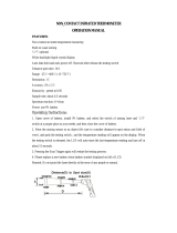
Field of View (Distance/Spot (D/S) value)
The object should be larger than the spot size calculated by the measurement Distance/Spot ratio
(Field of View, refer to INFRARED THERMOMETER SPECS). For accurate measurements, it is
recommended that the area to be measured is 1.5 times larger than the spot size calculated.
Careful collimating is required when the object is not large enough. If the temperature of the object
or a part of it is higher (or lower) than the ambient temperature. After aiming the probe, move the
probe slightly away. Ideal collimating is obtained when the display shows a maximum (or minimum)
reading. However the emissivity of the object and its ambient temperature must be roughly the
same.
Disturbance
●
Objects having low emissivity or objects having a low temperature yet high emissivity emit
little infrared energy.
●
For this reason, measurement of these objects are adversely effected by powerful infrared
energy radiated from nearby objects having high emissivity or high temperature.
●
For example, when such objects are measured in sunlight, erratic measurements can result
due to powerful radiated energy from the sun reflecting on the surface of the object and
entering the sensor.
TRACEABLE
®
NONCONTACT TEMPERATURE INDICATOR INSTRUCTIONS

Traceable
®
is a registered trademark of Control Company ©2009 Control Company. 92-4375-00 Rev. 2 060509
Emissivity Adjustment
The factory set emissivity value is 0.95. This will cover 90% of most measurement applications.
However to match the correct emissivity with the specific value of the object is important in order to
obtain the true temperature. When the emissivity of the object is known and its value is not 0.95, it
is recommended to adjust the emissivity value to obtain the best accuracy. Adjustment procedures
are as following:
a. Hold the “Emissivity Button” (3-3, Fig. 1) for at least 2 seconds continuously. The emissivity
value will flash, release the button.
b. Use the “Down (Rel.) Button” (3-4, Fig. 1), “Up (°C/°F) Button” ( 3-2, Fig. 1) to adjust the
desired emissivity value.
Hold the “Emissivity Button” at least 2 seconds continuously again. The emissivity value will stop
flashing. Release the button, the adjustment procedure is complete.
Special Surfaces
1. If the meter seems to be giving incorrect readings, then. the emissivity value for the object
may be incorrect. It may be necessary to change the emissivity value. (refer to Emissivity
Adjustment).
2. If the surface to be measured is covered by frost or other material, clean it to expose the
surface.
3. If the surface to be measured is highly reflective, apply masking tape or apply the known
“black body paint” (with an emissivity of 0.95).
Type K THERMOMETER MEASURING PROCEDURE
1. During the IR measurement, push “Sensor Button” (3-7, Fig. 1), the display will show the
symbol of K.
2. Insert the temperature probe plug into the “Thermocouple Input Socket” (3-11, Fig. 1).
3. Select the “°C“ “°F” display unit by pushing “°C/°F Button” (3-2, Fig. 1).
4. Display will show the temperature reading that was measured by the probe.
Note:
* When inserting the probe plug into the temperature input socket, please take care to observe the
correct polarity.
* For greater accuracy, when the probe plug is first inserted into the thermometer socket, or if the
probe is changed, the plug must be allowed to stabilize at the temperature of the socket, which is in
thermal contact with the cold junction compensation device. This will take a couple of minutes and
only applies if the probe plug has previously been exposed to an ambient temperature that is
different than the thermometer.
Offset Value adjustment:
Caused by the environment temperature change or other reasons. Then the measuring value may
drift few degrees (1, 2 or 3 degrees).
If found that the measuring values exist, little deviation especially when measuring the low
temperature. Adjusting the offset value will make the compensation and let the measured value be
precise.
Insert the temperature probe plug into the “Thermocouple Input Socket” (3-11, Fig. 1). The meter
will read the approximate room temperature.
The offset value adjustment procedures are as following:
a) Use two fingers to press the “Hold Button” (3-6, Fig. 1) AND “REC Button” (3-5, Fig. 1) together
and not release. The small digit (right bottom corner of LCD) will show the same value of main LCD
(big digit).
Hold down the “HOLD Button” and the “REC Button” together. Use the “Down Button” (3-4, Fig. 1),
“Up Button” (3-2, Fig 1) until
Then release all buttons, the small digit display (right bottom corner of the LCD) will disappear, the
offset adjustment procedures are completely finished.
Data Hold
1. During the measurement, pressing the “Hold Button” (3-6, Fig. 1) will freeze the measured
value and the LCD will show “HOLD” symbol.
2. Push the “Hold Button” again to cancel the data hold function
Data Record (Maximum, Minimum reading)
1. The DATA RECORD function displays the maximum and minimum readings. To start the
DATA RECORD function, press the “Rec Button” (3-5, Fig. 1) once. “Rec” symbol will
appear on the LCD.
2. With the “REC” symbol on the display:
(a) Push the “Rec Button” (3-5, Fig. 1) once, the “Max” symbol along with the
maximum value will appear on the display.
(b) Push the “Rec Button” again, the “Min” symbol along with the minimum value
will appear on the display.
(c) To exit the memory record function, push the “Rec Button” continuously at least
2 seconds. The display will revert to the current reading.
Relative measurement
1. During a measurement, the circuit will memorize the last measured values. When the “REL
Button” is pressed (3-4, Fig. 1) once the display will show zero value and a “REL” symbol
will appear on the LCD.
2. The new measured temperature values will be deducted from the above “Last measured
values” automatically.
3. To cancel the, relative measurement function push the “REL Button” once again. The “REL”
marker will disappear.
Note: When using the “Data Hold” and “Data Record” feature the relative function is prohibited.
Auto power off and the continue power on
1) For the function of Thermocouple Thermometer, the instrument has built—in “Auto Power
Shut—off” in order to prolong battery life. The meter will switch off within approx. 10 minutes
automatically.
2) To de-activate this feature and execute continuous power on, select the memory record function
during measurement, by pressing the “Rec Button” (3-5,Fig. 1).
BATTERY REPLACEMENT
1. When the left top corner of LCD display shows “ ” it is necessary to replace the battery.
However within specifications, measurement may still he made for several hours after the
low battery indicator appears before the instrument becomes inaccurate.
2. Open the “Battery Cover” (3-13, Fig. 1) away from the instrument and remove the battery.
3. Install a 9V battery (Alkaline or Heavy duty type) and replace the cover.
RS 232 PC SERIAL INTERFACE
The instrument features a computer output via 3.5 mm Terminal (3-8, Fig. 1).
The connector output is a 16 digit data stream which can he utilized to the user’s specific
application. An RS232 lead with the following connection will be required to link the instrument with
the PC serial input.
WARRANTY, SERVICE, OR RECALIBRATION
For warranty, service, or recalibration, contact:
CONTROL COMPANY
4455 Rex Road
Friendswood, Texas 77546 USA
Ph. 281-482-1714 Fax 281-482-9448
E-mail [email protected]
www.control3.com
Control Company is ISO 9001 Quality-
Certified by DNV and ISO 17025 accredited
as a Calibration Laboratory by A2LA.
/