Rev03 29-10-2019
Victron Energy B.V. / De Paal 35 / 1351 JG ALMERE / Nederland
Telefoon: (+31) (0)36 535 97 00 / www.victronenergy.com / e-mail: sales@victronenergy.com
BatteryProtect 48|100
ENGLISH
Installation
1. The BatteryProtect (BP) must be installed in a well-ventilated area and preferably close (max 50
cm) to the battery (but, due to possible corrosive gasses, not above the battery!). Voltage drop
over a long or undersized cable between the battery plus and the BP may result in unexpected
shutdown of the BP.
2. A properly sized fuse must be inserted according to local regulations in the cable between the
battery and the BP.
3. The BP is designed to allow current to flow from IN (battery) to
OUT (load) terminals only.
Reverse currents from OUT to IN terminals are strictly forbidden,
and will damage the device. If you wish to use the BP as a
disconnection for a charge source, you must orient the unit in the
system so that the current is flowing in the intended direction, IN
to OUT.
4. The short circuit protection of the BP will be activated if you try
to directly connect loads with capacitors on their input (eg
inverters). For that use case, please use the BP to control the
remote on/off switch on the inverter, instead of disconnecting the
higher power DC line.
5. Use a 1,5mm² wire (included) for the minus connection, which should be connected directly to
the battery minus. No other equipment should be connected to this wire.
6. The BP will automatically detect the system voltage after connection of plus and minus to the
battery. During voltage detection the 7 segment display shows a series of flashes between the top
and lower part.
7. Do not connect the load output until the BP has been fully programmed.
8. A remote on-off switch can be connected to the two pole connector (see figure 1) or between
pin 2-1 of the two pole connector and the battery plus.
9. A buzzer, LED or relay can be connected between the alarm output and the battery plus (see
figure 1). Maximum load on the alarm output: 50 mA (short circuit proof).
Load disconnect events and alarm output options
Buzzer or LED mode (buzzer or LED connected to the alarm output):
• In case of under voltage, a continuous alarm will start after 12 seconds. The BP will
disconnect the load after 90 seconds and the alarm will stop.
• In case of over voltage, the load will be disconnected immediately and an intermittent alarm
will remain on until the overvoltage problem has been corrected.
Relay mode (relay connected to the alarm output):
• In case of under voltage, the relay will engage after 12 seconds. The BP will disconnect the
load after 90 seconds and the relay will disengage.
• In case of over voltage, the load will be disconnected immediately and the alarm output will
remain inactive.
Li-ion mode:
• Connect the load disconnect output of the VE.Bus BMS to pin 2-1.
The load is disconnected immediately when the load disconnect output of the VE.Bus BMS
switches from ‘high’ to ‘free floating’ (due to battery cell under voltage, over voltage or over
temperature). The under voltage thresholds and alarm output of the BP are inactive in this
mode.
Programming
When switched off (remote open), the BP can be programmed for the desired voltages and modes
by connecting the PROG pin to the ground. Please see the programming table.
The display will first step through the shutdown and restart voltages. Disconnect the PROG pin
when the desired voltage is displayed.
The display will confirm the chosen voltage and default mode () twice.
Reconnect the PROG to ground if another mode is ( or ) is required. Disconnect when the
required mode is displayed.
The display will confirm the chosen voltage and mode twice.
Operation
There are 4 possible error modes, indicated by the 7 segment display:
• Short circuit detected
• Over load or over temperature
• Under voltage
• Over voltage
After 5 minutes the error is no longer displayed to reduce current consumption.
The decimal point of the 7 segment display is used for status indication:
• On solid: the BP attempts to activate the output
• Flash every 5s: output is active
• Flashing every 2s in Li-ion mode: output ‘connecting’
Remote control and short circuit
• The BP will connect the load 1 second after closing the remote contact.
• The BP will disconnect the load immediately when the remote contact is opened.
• When in Li-ion mode the BP will connect the load 30 seconds after the remote input of the BP
has been pulled high by the VE.Bus BMS. This delay increases to 3 minutes in case of
frequent switching.
• In case of a short circuit, the BP will attempt to connect the load every 5 seconds. After two
attempts the display will show (short circuit detected).
Programming table
7 segment display
Under voltage shut down
48V system
Under voltage restart
48V system
42V
48V
40V
46V
38V
46V
45V
53V
46V
55,2V
42V
51,2V
46V
51,2V
47,2V
51,2V
48V
52V
40V
52,8V
Buzzer or LED mode
Relay mode
Li-ion mode
Specifications
BatteryProtect
BP48|100
Maximum cont. load current
100A
Peak current
250
Operating voltage range
32–60
Current consumption
When on: 2mA When off or low voltage shutdown: 1,5mA
Alarm output delay
12 seconds
Max. load on alarm output
50mA (short circuit proof)
Load disconnect delay
90 seconds (immediate if triggered by the VE.Bus BMS)
Default thresholds
Disengage: 42V Engage: 48V
Operating temperature range
Full load: -40°C to +40°C (up to 60% of nominal load at 50°C)
Weight
0,2kg 0.5 lbs
0,5kg 0.6 lbs
0,8kg 1.8 lbs
Dimensions (hxwxd)
40 x 48 x 106m m
1.6 x 1.9 x 4.2 inch
59 x 42 x 115mm
2.4 x 1.7 x 4.6 inch
62 x 123 x 120mm
2.5 x 4.9 x 4.8 inch
Example Wiring Diagrams
OUT
OUT
IN
IN
OUT
IN
IN
OUT

Rev03 29-10-2019
Victron Energy B.V. / De Paal 35 / 1351 JG ALMERE / Nederland
Telefoon: (+31) (0)36 535 97 00 / www.victronenergy.com / e-mail: sales@victronenergy.com
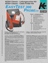
Connection diagram of the BP 48| 100
Connector pin numbering
Figure 1: Connection diagrams and pin numbering
Figure 2: System with 48V Li-ion battery set
(with 10kΩ series resistor)
Page is loading ...

Version 03 29-10-2019
Victron Energy B.V. / De Paal 35 / 1351 JG ALMERE / Pays-Bas
Téléphone : (+31) (0)36 535 97 00 / www.victronenergy.com / e-mail : [email protected]
Aansluitschema van de BP 48|100
Connectorpinnummering
Afbeelding 1: Verbindingsdiagrammen en pinnummering
Figuur 2: Systeem met 48V Li-ion-accuset
(met 10kΩ serie weerstand)
Page is loading ...
Page is loading ...
Page is loading ...

Rev03 29-10-2019
Victron Energy B.V. | De Paal 35 | 1351 JG ALMERE | Niederlande
Tel.: (+31) (0)36 535 97 00 / www.victronenergy.com / E-Mail: sa[email protected]
Kopplingsschema för BP 48|100
Numrering av anslutningsstift
Bild 1: Kopplingsscheman och stiftnumrering
Bild 2: System med 48 V-litiumjonbatteriset
(med10kΩ serieresistor)
Page is loading ...

Rev03 29-10-2019
Victron Energy B.V. | De Paal 35 | 1351 JG ALMERE | Países Baixos
Telefone: (+31) (0)36 535 97 00 / www.victronenergy.com / e-mail: sales@victronenergy.com
Anschlussplan des BP 48|100
Nummerierung der Anschlusspins
Abbildung 1: Anschlusspläne und Pin-Nummerierung
Abbildung 2: System mit 48V Li-Ionen-Batteriesatz
(mit 10kΩ Widerstand)
Page is loading ...

Rev03 29-10-2019
Victron Energy B.V. / De Paal 35 / 1351 JG ALMERE / Hollanda
Telefon: (+31) (0)36 535 97 00 / www.victronenergy.com / e-posta: sales@victronenergy.com
Esquema de ligações de BP 48| 100
Numeração de pinos e conectores
Figura 1: Esquema de ligações e numeração de pinos
Figura 2: Sistema com conjunto de bateria de Li-ion
de 48 V
(com resistência de série 10 kΩ)
Page is loading ...

Rev03 29-10-2019
Victron Energy B.V. / De Paal 35 / 1351 JG ALMERE / Hollanda
Telefon: (+31) (0)36 535 97 00 / www.victronenergy.com / e-posta: sales@victronenergy.com
Diagrama de conexión del SBP 48|100
Numeración de conectores pin
Figura 1: Diagramas de conexión y numeración de
pines
Figura 2: Sistema con juego de baterías de Li-ion de
48V
(Con resistencia de serie de 10kΩ)
Page is loading ...

Rev03 29-10-2019
Victron Energy B.V. / De Paal 35 / 1351 JG ALMERE / Hollanda
Telefon: (+31) (0)36 535 97 00 / www.victronenergy.com / e-posta: sales@victronenergy.com
Schema di connessione del BP 48| 100
Numerazione dei pin del connettore
Figura 1: Schemi di connessione e numerazione dei pin
Figura 2: Sistema con batteria agli ioni di litio da 48V
(con resistore da 10kΩ)
Page is loading ...

Rev03 29-10-2019
Victron Energy B.V. / De Paal 35 / 1351 JG ALMERE / The Netherlands
Phone: (+31) (0)36 535 97 00 / www.victronenergy.com / e-mail: [email protected]
BP 48| 100 Bağlantı şeması
Konnektör pimi numaraları
Şekil 1: Bağlantı şemaları ve pim numaraları
Şekil 2: 48V Li-ion akü seti içeren sistem
(10 kΩ serisi resistör ile)
/