Page is loading ...

Installation and Instruction Manual For:
CFS01 Series, CFS02 Series,
CFS11 Series, and CFS12 Series Housings
3M
™
Water Filtration Products
Installer: Please leave this manual with owner/operator.
Owner/Operator: Please retain for operation and future maintenance instructions.


WARNING
To reduce the risk associated with choking:
• Do not allow children under 3 years of age to have access to small parts during the installation of this product.
To reduce the risk associated with the ingestion of contaminants:
• Do not use with water that is microbiologically unsafe or of unknown quality without adequate disinfection before or after the system.
To reduce the risk associated with hazardous voltage due to an installer drilling through existing electric wiring or water
pipes in the area of installation:
• Do not install near electric wiring or piping which may be in path of a drilling tool when selecting the position to mount the
filter bracket.
To reduce the risk of physical injury:
• Depressurize system as shown in manual prior to cartridge removal.
EXPLANATION OF SIGNAL WORD CONSEQUENCES
WARNING
Indicates a potentially hazardous situation, which, if not avoided, could result in death or serious injury and/or
property damage.
CAUTION
Indicates a potentially hazardous situation which, if not avoided, may result in minor or moderate injury and/or
property damage.
CAUTION
Indicates a potentially hazardous situation, which, if not avoided, may result in property damage.
Read, understand, and follow all safety information contained in these instructions prior to installation and use
of the CFS Series Housings. Retain these instructions for future reference.
Intended Use:
The CFS Series Housings are intended for use in filtering potable water in the foodservice industry and have not been
evaluated for other uses. These systems are typically installed at the point-of-entry, and must be installed as specified in
the installation instructions.
IMPORTANT NOTES
• Failure to follow instructions may void warranty.
• Allow a minimum of 2” (5 cm) clear space under filter to facilitate cartridge change.
• Install with the inlet and outlet ports as labeled. Make sure not to reverse connections.
• The filter system may be used with metallic or non-metallic piping systems. Any non-metallic fittings used for the installation must be
of adequate rating for the line pressure.
CAUTION
To reduce the risk associated with property damage due to water leakage:
• Read and follow Use Instructions before installation and use of this system.
• Installation and Use MUST comply with all state and local plumbing codes.
• Protect from freezing, remove filter cartridge when temperatures are expected to drop below 40°F (4.4°C);
• Do not install on hot water supply lines. The maximum operating water temperature of this filter system is 100°F (37.8°C).
• Do not install if water pressure exceeds 125 psi (862 kPa). If your water pressure exceeds 80 psi (552 kPa), you must install a pressure
limiting valve. Contact a plumbing professional if you are uncertain how to check your water pressure.
• Do not install where water hammer conditions may occur. If water hammer conditions exist, you must install a water hammer arrester.
Contact a plumbing professional if you are uncertain how to check for this condition.
• Do not use a torch or other high temperature sources near filter system, cartridges, plastic fittings or plastic plumbing.
• On plastic fittings, never use pipe sealant or pipe dope. Use PTFE thread tape only, pipe dope properties may deteriorate plastic.
• Take care when using pliers or pipe wrenches to tighten plastic fittings, as damage may occur if overtightening occurs.
• Do not install in direct sunlight or outdoors.
• Do not install near water pipes which will be in path of a drilling tool when selecting the position to mount the bracket.
• Mount filter in such a position as to prevent it from being struck by other items used in the area of installation.
• Ensure that the location and fasteners will support the weight of the system when installed.
• Ensure all tubing and fittings are secure and free of leaks.
• The disposable filter cartridge MUST be replaced every 6 months or at the rated capacity or if a noticeable reduction in flow
rate occurs.
2
SAFETY INFORMATION

Your new CFS Series Housing is designed to reduce particulate matter and/or chlorine taste and odor, depending
upon the cartridge used.
The CFS01 and CFS02 Series filter systems come with internal shut-off valves in the filter head, eliminating the need
for external valves. The CFS11 and CFS12 Series filter systems require an external shut-off valve installed before the
system. All housings have either a transparent (T) housing or an opaque (S) sump. Both housing styles come with
3/4” NPT ports. Part number 6873231 is a mounting bracket and 3/4 x 1/2 reducing bushings, which are not sup-
plied with models CFS11 and CFS12 Series. It must be ordered separately.
Filter System Assembly:
1. Turn off incoming water supply.
IMPORTANT NOTES
• If bracket is provided, mount bracket onto filter head. Use mounting holes provided to mount system to a wall or support
structure.
• For those systems with internal shut-off valves, turn the valve on the filter head to “OFF” position.
2. Connect the incoming cold water supply to the filter system’s inlet water connection.
3. Connect the outlet port of the system to the outlet water line.
4. After all connections are complete, install cartridge, referring to the cartridge replacement instructions, if neces-
sary.
5. Turn on incoming water to the system.
IMPORTANT NOTES
• For those systems with internal shut-off valves, turn the valve on the filter head to the “ON” position. Pressurize system.
Check for leaks. Retighten connections if necessary. It is recommended that the unit be flushed for a maximum of 5
minutes in order to remove entrapped air and carbon fines (if activated carbon cartridges are used).
6. System is now ready for service.
3
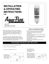
Procedure for Installing Filter:

4
CAUTION
To reduce the risk associated with property damage due to water leakage:
• The disposable filter cartridge MUST be replaced every 6 months or at the rated capacity or if a noticeable reduction in flow
rate occurs.
1. Turn off incoming water supply.
IMPORTANT NOTES
• For those systems with internal shut-off valves, turn the valve on the filter head to “OFF” position.
• For those systems with external shut-off valves, depress the pressure relief button on top of filter head to relieve pres-
sure in filter.
2. Unscrew sump from filter head. Empty water from sump and dispose of spent cartridge.
3. Clean and inspect all components, including the o-ring seal. Lubricate o-ring seals with a light coating of food grade
lubricant. Replace o-ring if there is visible damage.
4. Install new cartridge(s) into sump (over center post in a two high unit).
5. Screw sump into head until sump becomes snug and cartridge is sealed. HAND TIGHT IS SUFFICIENT. The use of a
wrench for tightening is not recommended and may result in damage.
6. Turn on incoming water supply.
IMPORTANT NOTES
• For those systems with internal shut-off valves, turn handle to “ON” position. Wait until the filter is filled with water and
check for leaks. Open and close the valve once to release trapped air.
• For those systems with external shut-off valves, depress pressure relief button on filter head until air is purged from
system.
• Flush new cartridge for 5 minutes prior to service.
• Replace cartridge when there is a decided drop in water flow at faucet or tap or line pressure downstream of filter
system drops below 20 psi (138 kPa). Do not leave valve in the “OFF” position for an extended period of time or use as a
substitute for main water line valve.
Cartridge Replacement Instructions

5
Cartridge Selection Guide
The CFS01/CFS11 Series and the CFS02/CFS12 Series are designed to use only 3M Water Filtration Products
replacement cartridges. Use of replacement cartridges other than those specified below may seriously compromise
water quality and/or cartridge life.
Replacement Cartridges for CFS01 and CFS11 Series Housings
Sediment
Model No. Part No. Micron Description Capacity
CFS8504-A 55847-03 10 Uniform density sediment reduction N/A
CFS124 56212-05 25 Graded density N/A
CFS110 56121-11 5 Sediment reduction N/A
Chlorine Taste and Odor
Model No. Part No. Micron Description Capacity
CFS117 55593-04 5 Granular activated carbon
10,000 gal. @ 2 gpm
(37,854 lit. @ 7.6 lpm)
CFS117-S 55594-12 5
Granular activated carbon
built-in scale inhibition
10,000 gal. @ 2 gpm
(37,854 lit. @ 7.6 lpm)
CFS186-A FSCTOB10N 5 Ultra carbon block
10,000 gal. @ 1.67 gpm
(37,854 lit. @ 6.3 lpm)
Sediment/Scale
Model No. Part No. Micron Description Capacity
CFS420IMF 55609-04 5
Graded density design
built-in scale inhibition
N/A
Replacement Cartridges for CFS02 and CFS12 Series Housings
Sediment
Model No. Part No. Micron Description Capacity
(2)
CFS8504-B
55847-05 10 Uniform density sediment reduction N/A
(2)
CFS124
56212-05 25 Graded density N/A
(2)
CFS110
56121-11 5 Sediment reduction N/A
Fine Silt Reduction
Model No. Part No. Micron Description Capacity
CFSFSR-5 55603-20 5 Absolute Fine silt reduction cartridge N/A
CFSFSR-10 55603-21 10 Absolute Fine silt reduction cartridge N/A
Chlorine Taste and Odor
Model No. Part No. Micron Description Capacity
(2)
CFS117
55593-04 5 Granular activated carbon
20,000 gal. @ 4 gpm
(75,708 lit. @ 15.1 lpm)
(2)
CFS117-S
55594-12 5
Granular activated carbon
built-in scale inhibition
20,000 gal. @ 4 gpm
(75,708 lit. @ 15.1 lpm)
(2)
CFS186-A
FSCTOB10N 5 Ultra carbon block
20,000 gal. @ 3.34 gpm
(75,708 lit. @ 12.6 lpm)
See PDS sheets for stated NSF claims.

CFS01 & CFS02 Head Assembly:
6981502
O-ring: 63597210C
Housing, 1-high, opaque (S): 6981131C
Housing, 1-high, transparent (T): 6981142
Housing, 2-high, opaque (S): 6981133
Housing, 2-high, transparent (T): 6981141C
Center Post: 6981731 (2 high only)
Wrench: 68434-32
CFS11 & CFS12 Head Assembly:
6981401C
O-ring: 63597210C
Housing, 1-high, opaque (S): 6981131C
Housing, 1-high, transparent (T): 6981142
Housing, 2-high, opaque (S): 6981133
Housing, 2-high, transparent (T): 6981141C
Center Post: 6981731 (2 high only)
Wrench: 68434-32
Mounting Bracket: 6873231
6

© 2008 3M Company. All rights reserved.
3M is a trademark of 3M Company.
CUNO are trademarks of 3M Company used under license.
Isoplast is a trademark of the Dow Chemical Company.
INSTR4075 0608
CUNO Incorporated,
a 3M Company
400 Research Parkway
Meriden, CT 06450, USA
Toll Free: 1.888.218.CUNO
Worldwide: 203.237.5541
Fax: 203.238.8701
www.cunofoodservice.com
CUNO Incorporated warrants this Product (excluding disposable filter cartridge(s)) to be free from defects in material and
workmanship for ten (10) years from the date of purchase. The disposable filter cartridge is warranted from defects in
material and workmanship for a period of one (1) year from the date of purchase. This warranty does not cover failures
resulting from abuse, misuse, alteration or damage not caused by CUNO or failure to follow installation and use instruc-
tions. If the Product is defective CUNO will replace the Product or refund your Product purchase price. CUNO will not be
liable for any indirect, special, incidental, or consequential damages arising from the use of this Product. Some states do
not allow the exclusion or limitation of incidental or consequential damages, so the above limitation may not apply to you.
To obtain warranty service, mail your request to Warranty Claims, CUNO Incorporated, 400 Research Parkway, Meriden, CT
06450. Proof of purchase (original sales receipt) must accompany the warranty claim, along with a complete description
of the Product, model number and alleged defect. This warranty gives you specific legal rights and you may have other
rights which vary from state to state, or country to country.
a 3M company
Limited Warranty
/