Page is loading ...

W164 N9221 Water Street • P.O. Box 450 • Menomonee Falls, Wisconsin 53052-0450 USA
PHONE: 262.251.3800 • 800.558.8744
USA/CANADA FAX: 262.251.7067 • 800.329.8744 U.S.A. ONLY
www.alto-shaam.com
Model:
ASC-4G
Manual
Control
C o n v e c t i o n O v e n
G a s
• I N STALLAT ION
• OP ERATIO N
• MAI NT ENAN CE
MN-28664 • 12/09
P R I N T E D I N U .S .A .

i
Delivery. . . . . . . . . . . . . . . . . . . . . . . . . . . . . . . . . . 1
Unpacking . . . . . . . . . . . . . . . . . . . . . . . . . . . . . . . . 1
Safety Procedures and Precautions . . . . . . . . . . . . 2
Installation
Site Installation. . . . . . . . . . . . . . . . . . . . . . . . . . 3
Clearance Requirements . . . . . . . . . . . . . . . . . . 3
Installation Requirements . . . . . . . . . . . . . . . . . . 4
Leveling . . . . . . . . . . . . . . . . . . . . . . . . . . . . . . . 4
Dimension Drawing . . . . . . . . . . . . . . . . . . . . . . 4
Gas Specifications. . . . . . . . . . . . . . . . . . . . . . 5-7
Electrical Connection . . . . . . . . . . . . . . . . . . . . . 8
Ventilation . . . . . . . . . . . . . . . . . . . . . . . . . . . . . 9
Stacking Instructions . . . . . . . . . . . . . . . . . . 10-11
Oven Stand Assembly Option . . . . . . . . . . . . . . 12
Operating Instructions
User Safety Information . . . . . . . . . . . . . . . . . . 13
Capacity . . . . . . . . . . . . . . . . . . . . . . . . . . . . . . 13
Options & Accessories . . . . . . . . . . . . . . . . . . . 13
Start-Up Operation . . . . . . . . . . . . . . . . . . . . . . 14
Manual Control Operation. . . . . . . . . . . . . . . . . 15
Chef Operating Tips . . . . . . . . . . . . . . . . . . . . . 16
Cooking Guidelines . . . . . . . . . . . . . . . . . . . . . 16
Care and Cleaning
Cleaning and Preventive Maintenance . . . . . . . 17
Protecting Stainless Steel Surfaces . . . . . . . . . 17
Cleaning Agents . . . . . . . . . . . . . . . . . . . . . . . . 17
Cleaning Materials . . . . . . . . . . . . . . . . . . . . . . 17
Equipment Care . . . . . . . . . . . . . . . . . . . . . . . . 18
Clean Daily. . . . . . . . . . . . . . . . . . . . . . . . . . . . 18
Exterior. . . . . . . . . . . . . . . . . . . . . . . . . . . . . . . 19
Motor Care . . . . . . . . . . . . . . . . . . . . . . . . . . . . 19
Service
Troubleshooting Guide . . . . . . . . . . . . . . . . . . . 19
Full Assembly View. . . . . . . . . . . . . . . . . . . . . . 20
Interior Oven Compartment View . . . . . . . . . . . 21
Electrical Side Panel View . . . . . . . . . . . . . . . . 22
Leg Assembly . . . . . . . . . . . . . . . . . . . . . . . . . . 23
Service Parts List . . . . . . . . . . . . . . . . . . . . . . . 24
Wire Diagrams
ASC-4G, Manual, 120V . . . . . . . . . . . . . . . . . . 28
Warranty
Transportation Damage and Claims . . Back Cover
Limited Warranty . . . . . . . . . . . . . . . . Back Cover

AS C- 4G Ga s C on ve ct io n O ve n - Ma nu al Co nt ro l • 1
D E L I V E R Y
T
his Alto-Shaam appliance has been
thoroughly tested and inspected to ensure only the
highest quality unit is provided. Upon receipt,
check for any possible shipping damage and report
it at once to the delivering carrier. See
Transportation Damage and Claims section
located in this manual.
This appliance, complete with unattached
items and accessories, may have been delivered in
one or more packages. Check to ensure that all
standard items and options have been received
with each model as ordered.
Save all the information and instructions
packed with the appliance. Complete and return
the warranty card to the factory as soon as
possible to ensure prompt service in the event of a
warranty parts and labor claim.
This manual must be read and understood by
all people using or installing the equipment
model. Contact the Alto-Shaam service
department if you have any questions concerning
installation, operation, or maintenance.
NOTE: All claims for warranty must include the
full model number and serial number of
the unit.
U N P A C K I N G
1. Carefully remove the
appliance from the
carton or crate.
NOTE: Do not discard the
carton and other
packaging material
until you have
inspected the unit
for hidden damage
and tested it for
proper operation.
2. Read all instructions in this manual carefully
before initiating the installation of this appliance.
DO NOT DISCARD THIS MANUAL.
This manual is considered to be part of the
appliance and is to be provided to the owner or
manager of the business or to the person
responsible for training operators. Additional
manuals are available from the Alto-Shaam
service department.
3. Remove all protective plastic film, packaging
materials, and accessories from the appliance
before connecting electrical power. Store any
accessories in a convenient place for future use.
®
®

AS C- 4G Ga s C on ve ct io n O ve n - Ma nu al Co nt ro l • 2
1. This appliance is intended to cook, hold or
process foods for the purpose of human
consumption. No other use for this appliance is
authorized or recommended.
2. This appliance is intended for use in commercial
establishments where all operators are familiar
with the purpose, limitations, and associated
hazards of this appliance. Operating
instructions and warnings must be read and
understood by all operators and users.
3. Any troubleshooting guides, component views,
and parts lists included in this manual are for
general reference only and are intended for use
by qualified technical personnel.
4. This manual should be considered a permanent
part of this appliance. This manual and all
supplied instructions, diagrams, schematics,
parts lists, notices, and labels must remain with
the appliance if the item is sold or moved to
another location.
N O T E : Used to notify personnel of
installation, operation, or
maintenance information that is
important but not hazard related.
C A U T I O N
Used to indicate the presence of a hazard that can
or will cause minor personal injury, property
damage, or a potential unsafe practice if the
warning included with this symbol is ignored.
C A U T I O N
Used to indicate the presence of a
hazard that can or will cause minor or
moderate personal injury or property
damage if the warning included with
this symbol is ignored.
D A N G E R
Used to indicate the presence of a
hazard that WILL cause severe
personal injury, death, or substantial
property damage if the warning
included with this symbol is ignored.
W A R N I N G
Used to indicate the presence of a
hazard that CAN cause personal injury,
possible death, or major property
damage if the warning included with
this symbol is ignored.
SAFETY PROCEDURES
AND PRECAUTIONS
Knowledge of proper procedures is essential to the
safe operation of electrically and/or gas energized
equipment. In accordance with generally accepted
product safety labeling guidelines for potential
hazards, the following signal words and symbols
may be used throughout this manual.
N O T E
For equipment delivered for use
in any location regulated by the
following directive:
DO NOT DISPOSE OF ELECTRICAL
OR ELECTRONIC EQUIPMENT WITH
OTHER MUNICIPAL WASTE.

AS C- 4G Ga s C on ve ct io n O ve n - Ma nu al Co nt ro l • 3
I N S T A L L A T I O N
The Alto-Shaam convection
oven must be installed in a
location that will permit the
oven to function for its
intended purpose and to
allow adequate clearance for
ventilation, proper cleaning,
and maintenance.
1. Hood installation is
required. (CHECK
LOCAL CODES
.)
2. The oven must be installed on a stable and
level surface. A non-combustible, heat
resistant, and fireproof surface is highly
recommended. If the oven is to be installed
on a combustible surface, factory supplied legs
or oven stand MUST
be used.
3. DO NOT install this oven in any area where it
may be affected by any adverse conditions such
as steam, grease, dripping water, high
temperatures, etc.
4. This appliance must be kept free and clear of
any combustible materials.
5. This appliance must be kept free and clear of
any obstructions blocking access for
maintenance or service.
W E I G H T
NET 393 lb (178 kg)
SHIPPING 438 lb (199 kg)
CRATE
40" H X 44" W X 53" D
D I M E N SI O N S: (1016mm x 1118mm x 1346mm)
MINIMUM ENTRY CLEARANCE 31-1/2" (800mm) UNCRATED
®
D I M E N S I O N S H x W x D:
EXTERIOR: 58-1/2" x 38" x 44-1/2"
(1486mm x 964mm x 1130mm)
INTERIOR: 24" x 29-1/8" x 25"
(610mm x 740mm x 635mm)
MINIMUM CLEARANCE REQUIREMENTS
COMBUSTIBLE NON-COMBUSTIBLE
SURFACES SURFACES
BACK 0" (0mm) 0" ( 0mm)
LEFT SIDE 2" (51mm) 0" ( 0mm)
RIGHT SIDE 2" (51mm) 2" (51mm)
FROM GREASE PRODUCING EQUIPMENT 6" (152mm) 6" (152mm)
ENTRY C LE ARANCE: 31-1/2" (800mm) UNCRATED
REC OMMENDE D S ERVICE ACC ESS
: 20" (508mm) RIGHT
CONTROL SIDE
D A N G E R
IMPROPER INSTALLATION,
A
LTERATION, ADJUSTMENT,
SERVICE, OR MAINTENANCE COULD
RESULT IN SEVERE INJURY, DEATH,
OR CAUSE PROPERTY DAMAGE.
READ THE INSTALLATION,
OPERATING AND MAINTENANCE
INSTRUCTIONS THOROUGHLY
BEFORE INSTALLING OR SERVICING
THIS EQUIPMENT.
C A U T I O N
DO NOT LIFT OR MOVE THE
OVEN BY USING THE DOORS
OR THE DOOR HANDLES.
C A U T I O N
M
ETAL PARTS OF THIS EQUIPMENT
BECOME EXTREMELY HOT WHEN IN
OPERATION. TO AVOID BURNS,
ALWAYS USE HAND PROTECTION
WHEN OPERATING THIS APPLIANCE.
D A N G E R
DO NOT store or use gasoline or other
flammable vapors or liquids in the
vicinity of this or any other appliance.
S I T E I N S T A L L A T I O N

AS C- 4G Ga s C on ve ct io n O ve n - Ma nu al Co nt ro l • 4
I N S T A L L A T I O N
The oven must be mounted on the factory equipped
oven legs or on an optional oven stand. Installation
on a solid or concrete base that in any way restricts
air flow may void the warranty.
All clearances for a proper ventilation air supply
must be maintained to minimize fire hazard. Do
not locate the oven immediately adjacent to any
other heat-generating appliance.
A number of adjustments are associated with initial
installation and start-up. Adjustments must be
conducted by a qualified service technician.
Installation and start-up adjustments are the
responsibility of the dealer or user. These
adjustments include but are not limited to
thermostat calibration, door adjustment, leveling,
and gas pressure verification. The Platinum series
oven burners are factory-adjusted with fixed air
openings and require no field adjustment.
LEVELING
The oven should
be leveled
before the gas supply is
connected. Level the oven from side-to-side and
front-to-back with the use of a spirit level. For
ovens installed on a mobile stand, it is important
that the floor surface be level due to the probability
of frequent oven repositioning.
We recommend checking the level of the oven
periodically to make certain the floor has not
shifted nor the oven moved.
NOTE: Failure to properly level this oven can
cause improper function as a result of
erratic burner combustion and will result
in the uneven baking of products
consisting of semi-liquid batter.
I N S T A L L A T I O N R E Q U I R E M E N T S
30-5/8" (778mm)
44-1/2" (1130mm)
58-1/2" (1486mm)
31-15/16" (810mm)
38" (965mm)
25-11/16" (652mm)
3-5/16" (84,4mm)
29-1/8" (740mm)
1/2"
GAS INLET
3-5/32"
(80,1mm)
6-15/16" (176mm)
9-15/16" (252mm)
LINE CORD ENTRANCE
3-11/16" (93mm)
6' (1828mm)
LINE CORD ENTRANCE
31-1/16" (789mm)
4" (102mm)
1/2" GAS INLET
12-15/16"
(329mm)
EXHAUST
VENT
CAVITY WIDTH
123°
129°
26-1/2" (673mm)
54-5/8" (1387mm)
MODEL ASC-4G
W A R N I N G
Inadequate ventilation, or failure to
ensure an adequate supply of fresh
air will result in a high ambient
temperature at the rear of the
appliance. An excessive ambient
temperature can cause the thermal-
overload protection device on the
blower motor to trip resulting in severe
damage to the blower motor.
C A U T I O N
TO PREVENT PERSONAL INJURY,
USE CAUTION WHEN MOVING OR
LEVELING THIS APPLIANCE.

AS C- 4G Ga s C on ve ct io n O ve n - Ma nu al Co nt ro l • 5
G A S S U P P LY & I N S T A L L A T I O N
INSTALLATION REQUIREMENTS
GAS CONNECTION: 3/ 4" NPT
C
HECK PLUMBING CODES FOR PROPER SUPPLY LINE SIZING TO
A
TTAIN BURNER MANIFOLD
NOTE: If a flexible gas line is used, it must be AGA
approved, commercial type and at least 1" I.D.
GAS P R ESSUR E CHART
The gas valve and burner have been fitted
according to the gas type specified on the
identification name plate.
TECHNICAL SPECIFICATIONS
N a t u r a l G a s
Min. connected pressure 7.0" W.C. 1.74 kPa
Max. connected pressure 14.0" W.C. 3.48 kPa
Orifice Size 1/8
Manifold pressure 5.0" W.C. 1.25 kPa
Gross thermal output
50,000 Btu/hr
Propane Gas
Min. connected pressure 11.0" W.C. 2.74 kPa
Max. connected pressure 14.0" W.C. 3.48 kPa
Orifice Size #43
Manifold pressure 10.0" W.C. 2.49 kPa
Gross thermal output
50,000 Btu/hr
D A N G E R
CONNECTING TO THE WRONG GAS
SUPPLY COULD RESULT IN FIRE OR
AN EXPLOSION CAUSING SEVERE
INJURY AND PROPERTY DAMAGE.
W A R N I N G
TO AVOID SERIOUS PERSONAL
INJURY, installation of this appliance
must conform to local, state, and
national codes; the current edition of
the American National Standard
Z223.1, National Fuel Gas Code, and
all local municipal building codes. In
Canada, installation must be in
accordance with Standard CAN/CSA
B 149.1 and Installation Codes - Gas
Burning Appliances, and local codes.
G A S S P E C I F I C A T I O N S
FIELD CONVERSION OF FUEL TYPE
To convert from either fuel type, replace the orifice
located at the burner inlet with the desired orifice.
Replace the spring kit located on the front left side of
the valve. Remove the cap and nylon screw, replace
spring and nylon screw with desired kit. Set the
manifold pressure to the corresponding values located
under technical specifications.
F U E L T Y P E O R I F I C E S I Z E O R I F I C E P / N M A N I F O L D P R E S S U R E
Natural 1/8 OR-29172 5.0 IN/WC
Propane # 43 OR-29054 10.0 IN/WC
C O N V E R S I O N S P R I N G K I T S
Natural VA-28821 Propane VA-28444

AS C- 4G Ga s C on ve ct io n O ve n - Ma nu al Co nt ro l • 6
G A S S U P P LY & I N S T A L L A T I O N
GAS REQUIREMENTS
The gas inlet is located at the back of the oven.
Code requires the installation of a manual gas
shutoff valve to be installed in the gas line ahead
of the oven. This oven is also equipped with fixed
burner orifices determined by the elevation
specified as the initial installation location.
The oven is furnished with a regulator integral to
the operation of the gas solenoid valve and may
not require an additional external regulator. To
ensure safe and proper operation, the gas
pressure regulator installed in the oven is
required for use with both natural gas and
propane. If the connected pressure exceeds 14.0"
W.C. (3.48 kPa), a step-down regulator is
required. A step-down regulator is not the
responsibility of the manufacturer.
Use an approved pipe sealant at all connections.
Do not use Teflon® tape. Gas supply connections
and pipe joint compound must be resistant to the
action of propane gases. Pipes must be clean, free
of obstructions and pipe joint compound.
GAS CONNECTION
In the U.S.A., installation must conform to local
codes or, in the absence of local codes, with the
current edition of the N ational Fuel Gas Code,
NFPA-54 and ANSI Z223.1-1980 (latest edition).
In Canada, installation must be in accordance
with local codes, CAN/CGA-B149.1, Installation
for N atural Gas Bu rning A pp liances and
Equipm ent (latest edition) or CAN/CGA-B149.2
Installation for Propane Burning A pp liances and
Equipm ent (latest edition).
The inlet supply line must be properly sized
to accommodate all individual appliances
simultaneously used on the same line but
must never be smaller than 3/4" NPT.
INCORRECT CORRECT
A
B
C
D
E
F
G
H
GAS INTAKE
A-G Installation elbow
B Wall Valve
C-D Three-piece union fitting
(minimum 1 per installation)
E-F End connector for the flexible tube
H Marking line
D A N G E R
Installation, air adjustment and/or
s
ervice work must be in accordance
with all local codes and must be
performed by a certified service
technician qualified to work on
gas appliances.

AS C- 4G Ga s C on ve ct io n O ve n - Ma nu al Co nt ro l • 7
G A S S U P P LY & I N S T A L L A T I O N
GAS CONNECTION
➥ FOR OVENS ON CASTERS
The oven must be supplied with a flexible
connector that complies with The Standard for
Connectors for Movable Gas Appliances, ANSI
Z21.69, CGA 6.16 and addenda Z21.69a (latest
editions). A quick disconnect device must be
installed to comply with The Standard for Quick
Disconnect Devices for Use with Gas Fuel, ANSI
Z21.41 and CAN1-6.9 (latest editions). A flexible
connector is not supplied by the factory.
Adequate means must be
provided to limit the
movement of the
appliance. Limitation of
movement must be made
without depending on the
connector, the quick
disconnect device, or the
associated piping designed
to limit oven movement.
Mounting holes for a
restraining device are
located on the lower back
flange of the oven chassis.
Sh ut t he g as s up pl y O F F if i t becomes
ne ce ss ar y to disconnect the restraint.
Re co nn ec t th e res tr ai nt i mm ed ia te ly
fo ll ow in g th e ret ur n o f th e ov en t o its
or ig in al p os it io n. Turn the gas supply ON
after the restraint has been reconnected.
LEAK TESTING
Use a soap and water solution on all gas supply
line connections.
CORRECT
RESTRAINT
D A N G E R
NEVER USE AN OPEN
FLAME TO LEAK TEST.

AS C- 4G G a s Con ve ct io n Ove n - M an ua l C on tr ol • 8
I N S T A L L A T I O N
This appliance is equipped with a three-prong
grounding plug. For your protection against shock
hazard this appliance should be plugged directly into
a properly grounded three-prong receptacle. Do not
cut or remove the grounding prong from this plug.
Plug the unit into a properly grounded receptacle
ONLY, positioning the unit so that the plug is easily
accessible in case of an emergency. Arcing will occur
when connecting or disconnecting the unit unless all
controls are in the “O
FF
” position.
Proper receptacle or outlet configuration or
permanent wiring for this unit must be installed by a
licensed electrician in accordance with applicable
local electrical codes.
E L E C T R I C A L C O N N E C T I O N
E L E C T R I CA L
VOLTAGE PHASE CYCLE/ HZ AMPS
120 1 60 12.5
6' (1828mm) cord with plug included: NEMA 5-15P
D A N G E R
ENSURE POWER SOURCE
MATCHES VOLTAGE STAMPED
ON APPLIANCE NAMEPLATE.
D A N G E R
To avoid electrical shock, this
appliance MUST be adequately
grounded in accordance with local
electrical codes or, in the absence of
local codes, with the current edition
of the National Electrical Code
ANSI/NFPA No. 70. In Canada, all
electrical connections are to be
made in accordance with CSA C22.1,
Canadian Electrical Code Part 1 or
local codes.

AS C- 4G G a s Con ve ct io n Ove n - M an ua l C on tr ol • 9
I N S T A L L A T I O N
V E N T I L A T I O N
VENTILATION HOODS
Proper venting along with a sufficient quantity of
make-up air is essential for proper oven operation.
A mechanically driven, canopy exhaust hood is
the preferred method of ventilation and must
conform to local codes along with the current
version of NFPA-96 Vapor Removal from Cooking
Equipment (latest edition). The oven hood must
extend 6" (152mm) beyond all sides of the oven.
The distance from the floor to the bottom edge of
the hood should be between 6'6" (1981mm) and
7' (2134mm).
A ventilation hood that supplies make-up air
down the back vertical wall should be avoided
since air currents can interfere with the oven flue
exits. If such installation is unavoidable, an
additional draft hood, specifically designed to
deflect downdrafts, must be installed.
DIRECT VENTING
When necessary, direct venting can be used in
situations where space is limited or to help
offset the high cost of ventilation hoods.
Direct venting should be installed in compliance
with local codes by a certified professional.
In the absence of local codes, refer to National
Fuel Code NFPA 54, ANSI Z223.1 (latest revision).
D A N G E R
FAILURE TO VENT THIS APPLIANCE
PROPERLY MAY BE HAZARDOUS TO
THE HEALTH OF THE OPERATOR.
Equipment damage, operational
problems and unsatisfactory baking
performance may also be the
consequence of improper venting.
Any damage sustained by a failure to
properly vent this oven are not
covered under warranty.
D A N G E R
Installation, air adjustment and/or
service work must be in accordance
with all local codes and must be
performed by a certified service
technician qualified to work on
gas appliances.
Ventilating hoods and exhaust systems shall
be permitted to be used to vent appliances
i
nstalled in commercial applications.
Where automatically operated appliances are
vented through a ventilating hood or exhaust
system equipped with a damper or with a
power means of exhaust, provisions shall be
made to allow the flow of gas to the main
burners only when the damper is open to a
position to properly vent the appliance and
when the power means of exhaust is in
operation.
I
N ACCORDANCE WITH
NFPA 54
C
OMMONWEALTH OF MASSACHUSETTS ONLY
.

AS C- 4G G a s Con ve ct io n Ove n - M an ua l C on tr ol • 10
I N S T A L L A T I O N
S T A C K I N G K I T ( 5 0 0 5 7 8 3 )
3
4
5
1
2
Rev 04/09
C A U T I O N
TO PREVENT PERSONAL INJURY,
USE CAUTION WHEN MOVING OR
LEVELING THIS APPLIANCE.
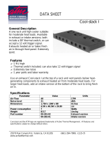
STACKING INSTRUCTIONS
A) Remove side panels.
B) Knock out the mounting holes on top of
the intended bottom oven.
C) After legs or casters have been installed
on the bottom oven, place the upper
oven on top of lower unit. Align.
D) Bolt at 1 and 2.
E) Using mounting holes on bottom oven,
bolt at 4.
I T E M D E S C R I P T I O N PA R T N O . Q T Y
1 BRACKET, ATTACHMENT, FSCO 1004369 2
2 SCREW, #10 SMS .5LG SC-26520 20
3 SCREW, HEX HEAD, 5/16-18X 1”LG SC-2191 2
4 5/16 FLAT WASHER WS-23725 2
5 WASHER, LOCK, 5/16 DIA. WS-2867 2
M O U N T I N G
H O L E S
S I D E
PA N E L

AS C- 4G G a s Con ve ct io n Ove n - M an ua l C on tr ol • 11
I N S T A L L A T I O N
S TA C K I N G , G A S P L U M B I N G & F L U E I N T E R C O N N E C T ( 5 0 0 3 7 8 8 )
7
8
1
2
3
4
5
6
Rev 04/09
ASSEMBLY INSTRUCTIONS
FIRST: Assemble plumbing items 2 thru 6 as shown
NEXT: Assemble items 7, 8, & 1 as shown
I T E M D E S C R I P T I O N PA R T N O . Q T Y
1 SCREW, #10 SMS .5LG SC-26520 24
2 ELBOW 90 DEG STREET 1/2" NPT EB-26489 1
3 FITTING, UNION 1/2" NPT FT-26488 1
4 1/2" MANIFOLD PIPE PP-26529 1
5 FITTING, TEE 1/2" NPT FT-26487 1
6 1/2" MANIFOLD PIPE PP-26528 1
7 OUTER FLUE BOX, DBL STACK 1004372 2
8 CAP, FLUE BOX, DBL STACK 1004373 2

AS C- 4G G a s Con ve ct io n Ove n - M an ua l C on tr ol • 12
I N S T A L L A T I O N
O V E N S T A N D A S S E M B LY
8
1
1
7
3
4
2
9
1
2
34-5/16" (876mm)
5
6
2
38" (956mm)
O
VEN STAND
5003489 S
HOWN
I T E M D E S C R I P T I O N PAR T N O . Q T Y
1 LEG SUPPORT ASSEMBLY 5003488 2
2 CHANNEL, SUPPORT 1004459 2
3 LEG LG-22185 4
*CASTERS, RIGID CS-25674 2
*CASTERS, SWIVEL W/BRAKE CS-25675 2
4 BRACKET, STAND 1004461 1
5 BRACKET, ATTACHMENT 1004369 2
6 CHANNEL, BACK 1004460 1
7 SHELF, STAND 1004466 1
8 RACK, OVEN SUPPORT SR-26551 2
9 OVEN RACK SH-26395 6
10 SCREWS, 1/4-20 X 1/2 HEX HEAD SC-22729 27
11 NUT, 1/4-20 NYLON INSERT, 18-8 S/S NU-23984 27
12 LOCK WASHER, 1/4" STAINLESS STEEL WS-2294 27
*NOT SHOWN

O P E R A T I N G I N S T R U C T I O N S
AS C- 4G G a s Con ve ct io n Ove n - M an ua l C on tr ol • 13
U S E R S A F E T Y I N F O R M A T I O N
The Platinum Series gas convection oven is intended
for use in commercial establishments by qualified
operating personnel where all operators are familiar
with the purpose, limitations, and associated
hazards of this appliance. Operating instructions
and warnings must be read and understood by all
operators and users.
Instructions to be followed in the event the odor of
gas is detected should be posted in a prominent
location. Specific instructions are available from
your local gas supplier.
O P T I O N S & A C C E S S O R IE S
■■
CASTER SET, 6" (152mm)
FOR MOBILE STACK APPLICATIONS 5003790
■■
COOLING RACK (ONLY) FOR OVEN STAND 5003791
LEG SET (4)
■■
6" (152mm), with Bullet Feet 5003794
■■
6" (152mm), with Seismic Feet 5003795
■■
25" (635mm), with Seismic Feet 5003785
■■
PANEL FOR BACK, Stainless Steel 5005876
SHELF, OVEN RACK
■■
INTERCHANGEABLE WITH COOLING RACK SH-26795
STACKING HARDWARE
S EE IND I V I D U AL S TA CKI N G C O M B I N ATI O N S P E CIF I C ATIO N S H E E T S .
STAND, STAINLESS STEEL
■■
Mobile with Cooling Racks & Casters 5003786
■■
Stationary with Cooling Racks & Bullet Feet 5003489
■■
Stationary with Cooling Racks & Seismic Feet 5003787
■■
VENTING KIT (TO VENT DIRECTLY TO OUTSIDE) 5003797
P R O D U C T \PA N C A PA C I T Y
72 lb (33 kg)
MAXIMUM
45 qts (43 liters)
12 (twelve): 18" x 26" x 1"
FULL-SIZE SHEET PANS
C A U T I O N
M
ETAL PARTS OF THIS EQUIPMENT
BECOME EXTREMELY HOT WHEN IN
OPERATION. TO AVOID BURNS,
ALWAYS USE HAND PROTECTION
WHEN OPERATING THIS APPLIANCE.
D A N G E R
BEFORE STARTING THE
APPLIANCE, MAKE CERTAIN
YOU DO NOT DETECT THE
ODOR OF GAS.
IF THE ODOR OF GAS IS DETECTED:
• DO NOT attempt to light any appliance.
• DO NOT touch any electrical switches.
• Extinguish any open flame.
• Use a telephone OUTSIDE THE
PROPERTY & IMMEDIATELY
contact your gas supplier.
• If unable to contact your gas supplier,
contact the fire department.
IN THE EVENT OF A POWER FAILURE:
• TURN ALL SWITCHES OFF.
• WAIT UNTIL POWER IS RESTORED BEFORE
ATTEMPTING TO OPERATE THE OVEN.
NOTE: If su ch an event has occu rred, it is
strongly recommended that you ensure the food in
the oven is safe for consumption according to local
health regulations.

O P E R A T I N G I N S T R U C T I O N S
AS C- 4G G a s Con ve ct io n Ove n - M an ua l C on tr ol • 14
S T A R T- U P O P E R A T I O N
BEFORE INITIAL USE:
Interior oven surfaces must be heated to remove
s
urface oils and the accompanying odors produced
during the first use of the oven.
1. Wipe all wire shelves, side racks and the full
oven interior with a clean, damp cloth.
2. Close the oven doors, press the power switch
to the “
ON” position, and set the thermostat to
300°F (149°C).
3. Allow the oven to cycle for approximately 2
hours or until no odor is detected.
PAN/SHELF POSITIONS:
The oven includes 6 chrome plated wire shelves
with two removable side racks and 12 shelf
positions spaced at 1-3/4" (43mm).
1. The best arrangement for broiling, baking
cookies and for other baked goods under
2-1/2" (65mm) in height. This
arrangement can also be used as the
maximum capacity for reconstituting
frozen entrées.
2. General baking with the use of sheet
pans for products under 3-1/2" (89mm)
in height. Products include cakes, pies,
muffins, or extended dishes in
12" x 20" x 2-1/2" deep pans
(530mm x 325mm x 65mm GN 1/1).
3. Ideal positions for baking bread,
meringue, or extended dishes and roasts
in pans not to exceed 5-1/2" (140mm)
in height.
4. Arrangement necessary for roasting
whole turkey or roasts up to 7" (178mm)
in height.
PREHEATING:
Always preheat the oven for a minimum of 20 minutes before cooking product. Follow the operating
instructions indicated on the next page of this manual.
POSITION
2
4
6
8
12
POSITION
1
4
7
10
POSITION
1
5
9
POSITION
1
6
C A U T I O N
METAL PARTS OF THIS EQUIPMENT
BECOME EXTREMELY HOT WHEN IN
OPERATION. TO AVOID BURNS,
ALWAYS USE HAND PROTECTION
WHEN OPERATING THIS APPLIANCE.

O P E R A T I N G I N S T R U C T I O N S
AS C- 4G G a s Con ve ct io n Ove n - M an ua l C on tr ol • 15
햲
햴
햳
햶
햷
햵
NOTE: Under normal operating conditions, the burner will ignite within four
(4) seconds. If the burner does not ignite within fifteen (15) seconds,
usually as a result of insufficient gas flow or air trapped in the gas
l
ine, the ignition system will lock out and must be reset.
1. Press POWER SWITCH 쐃 to the ON position.
2. Press FAN SWITCH 쐋 to high or low fan speed.
3. Set THERMOSTAT 쐄 to the temperature desired.
The LIGHT OFF\OVEN READY indicator light will illuminate and the
oven will begin to heat to the set temperature. When the set temperature is
reached, LIGHT OFF\OVEN READY indicator light will go out.
4. When the oven is preheated, load product into the oven. For best results,
always load the oven from the bottom to the top position and load as
quickly as possible to retain maximum oven compartment heat.
5. Set TIMER 쐂 by rotating the knob clockwise. The timer will begin to
count down. When the timer reaches zero, the oven will produce an
audible alert signal that will continue for three (3) minutes or until the
timer knob is turned counterclockwise to the OFF position.
SHUTDOWN PROCEDURE
1. Rotate THERMOSTAT 쐄 to the OFF position.
2. Set the FAN SWITCH 쐋 to FULL SPEED.
3. Open the oven doors.
4. Press POWER SWITCH to the COOL DOWN 쐇 position. To help protect
the motor, allow the fan to operate until the oven is cool.
5. When the oven is cool, press the POWER SWITCH 쐃 to the OFF position.
GAS IGNITION LOCKOUT RESET
1. Rotate THERMOSTAT 쐄 to the OFF position.
2. Set the FAN SWITCH 쐋 to FULL SPEED to exhaust any residual gas.
3. Wait for a period of five (5) minutes before attempting a restart.
ALLOW A MINIMUM OF 20 MINUTES TO PREHEAT THE OVEN.
NOTE: Turn the main circuit breaker for this appliance OFF if the oven will
not be in operation for an extended period of time.

AS C- 4G G a s Con ve ct io n Ove n - M an ua l C on tr ol • 16
C H E F O P E R AT I N G T I P S
The Alto-Shaam convection oven will provide the best results and longest possible
service with the utilization of the following suggestions and guidelines.
NOTE: Moisture will escape around the doors when baking products with a heavy
moisture content such as chicken, potatoes, etc. This is a normal operating condition.
Do not place anything directly
on the bottom of the oven cavity.
A T T H E E N D O F T H E D A Y ,
U T I L I Z E T H E C O O L - D O W N M O D E
A N D O P E N T H E O V E N D O O R S .
1. Thoroughly preheat the oven for approximately
20 minutes before use.
2. As a general rule, the cooking temperature can
be set lower than the temperature used in a
conventional oven. Cooking time may also be
shorter. It is suggested the first batch of each
product prepared be monitored closely to check
for variances.
3. Maintain a record of the temperatures, times, and
load capacities established for products cooked on
a regular basis since they will be the same or
similar for succeeding loads.
4. When practical, start cooking the lowest
temperature products first and gradually work up
to products with a higher cooking temperature.
5. If the cooking temperature setting for the previous
product is more than 10°F (5°C to 6°C) higher
than the temperature needed for the next load,
use the FAN COOL-DOWN feature to decrease
the oven temperature before setting the oven to a
lower temperature.
6. Work as quickly as possible when loading the
oven to prevent heat loss.
7. When the audible signal indicates the time has
expired, remove the food product from the oven
as quickly as possible to avoid overcooking.
8. Pans should be centered between side racks and
each shelf should be loaded evenly to allow proper
air circulation within the oven compartment.
9. To assure even cooking when baking, weigh or
measure the product in each pan.
10. When cooking six pans of product, start from the
top of the oven and use side rack positions 2, 4, 6,
8, 10, and 12.
11. Do not overload the oven. A maximum 6 sheet
pan capacity is suggested for most items such as
cakes, cookies, rolls, etc. A maximum of 12 sheet
pans may be used for items such as fish sticks,
chicken nuggets, and hamburgers. It will be
necessary to adjust cooking times accordingly.
Refer to product/pan capacities indicated in
this manual.
12. To obtain an evenly baked product, muffin pans
should be placed in the oven with the short side
of each pan facing the front of the oven.
13. When rethermalizing frozen casseroles, preheat the
oven 100°F (38°C) over the suggested temperature
to compensate for the introduction of a large
quantity of frozen product into the oven
compartment. Reset the thermostat to the correct
cooking temperature after the oven is loaded.
14. Use a pan extender or two inch (51mm) deep,
18” x 26” pans for batter-type products that weigh
more than 8 pounds (3 to 4 kg), i.e.; pineapple
upside-down cake.
15. To avoid obstructing airflow that would result
in uneven cooking results, never place anything
directly on the bottom of the oven cavity.
Cooking Guidelines
Food Temperature
Time
(Minutes)
Food Temperature
Time
(Minutes)
Cakes, Sheet 325°F 163°C 25
Macaroni & Cheese
(frozen, full oven)
350°F 177°C 90
Chicken pieces (30 breasts &
thighs, 25 legs & wings)
400°F 204°C 25
Macaroni & Cheese
(refrigerated)
350°F 177°C 30
Chicken halves 400°F 204°C 40 Muffins 325°F 163°C 13-15
Beef patties 400°F 204°C 8 Pies, Frozen 325°F 163°C 40
Bacon 350°F 177°C 16 Pizzas, Individual 325°F 163°C 15
Fish, frozen (5 oz.) 350°F 177°C 15 Potatoes, Baked 350°F 177°C 50
Macaroni & Cheese
(frozen, 1 pan)
350°F 177°C 50
Sandwiches, Grilled Cheese 400°F 204°C 4-6
Tater tots 450°F 232°C 10

C A R E A N D C L E A N I N G
AS C- 4G G a s Con ve ct io n Ove n - M an ua l C on tr ol • 17
PROTECTING STAINLESS STEEL SURFACES
It is important to guard against
corrosion in the care of
stainless steel surfaces.
Harsh, corrosive, or
inappropriate chemicals can
completely destroy the
protective surface layer of stainless steel.
Abrasive pads, steel wool, or metal implements
will abrade surfaces causing damage to this
protective coating and will eventually result in
areas of corrosion. Even water, particularly hard
water that contains high to moderate
concentrations of chloride, will cause oxidation
and pitting that result in rust and corrosion. In
addition, many acidic foods spilled and left to
remain on metal surfaces are contributing factors
that will corrode surfaces.
Proper cleaning agents, materials, and
methods are vital to maintaining the appearance
and life of this appliance. Spilled foods should be
removed and the area wiped as soon as possible
but at the very least, a minimum of once a day.
Always thoroughly rinse surfaces after using a
cleaning agent and wipe standing water as quickly
as possible after rinsing.
CLEANING AGENTS
Use non-abrasive cleaning products designed for
use on stainless steel surfaces. Cleaning agents
must be chloride-free compounds and must not
contain quaternary salts. Never use hydrochloric
acid (muriatic acid) on stainless steel surfaces.
Always use the proper cleaning agent at the
manufacturer's recommended strength.
Contact your local cleaning supplier for
product recommendations.
CLEANING MATERIALS
The cleaning function can usually be accomplished
with the proper cleaning agent and a soft, clean
cloth. When more aggressive methods must be
employed, use a non-abrasive scouring pad on
difficult areas and make certain to scrub with the
visible grain of surface metal to avoid surface
scratches. Never use wire brushes, metal scouring
pads, or scrapers to remove food residue.
C L E A N I N G A N D P R E V E N T I V E M A I N T E N A N C E
C A U T I O N
TO PROTECT STAINLESS STEEL
SURFACES, COMPLETELY AVOID
THE USE OF ABRASIVE CLEANING
COMPOUNDS, CHLORIDE BASED
CLEANERS, OR CLEANERS
CONTAINING QUATERNARY SALTS.
NEVER USE HYDROCHLORIC ACID
(MURIATIC ACID) ON STAINLESS
STEEL. NEVER USE WIRE
BRUSHES, METAL SCOURING
PADS OR SCRAPERS.
N
O
S
C
R
A
P
E
R
S
N
O
W
I
R
E
B
R
U
S
H
E
S
N
O
S
T
E
E
L
P
A
D
S

C A R E A N D C L E A N I N G
AS C- 4G G a s Con ve ct io n Ove n - M an ua l C on tr ol • 18
C L E A N T H E O V E N O N A D A I LY B A S I S
1. After the oven has cooled, remove all detachable
items such as wire shelves, side racks, and drip
pan. Clean these items separately.
2. Remove any food scraps from shelves, shelf
supports, and blower fan wheel. Convection
baffle openings must be kept clear of food
scraps and grease.
3. Wipe the interior metal surfaces of the oven
with a paper towel to remove any remaining
food debris.
4. Clean interior with a damp cloth or sponge
and any good commercial detergent at the
recommended strength.
5. For baked-on food deposits, use a non-caustic
and non-toxic commercial oven cleaner
appropriate for the interior oven surface of
your oven. Follow the product manufacturer's
instructions carefully for the use of this
product. Any commercial oven cleaner
must be approved for use on food contact
areas. Remove soil with the use of a plastic
scouring pad.
6. Wipe door gaskets
thoroughly since these areas
harbor food debris and grease.
7. Rinse surfaces by wiping with a
clean cloth or sponge and clean
warm water.
8. Remove excess water with a sponge and wipe
dry with a clean cloth or air dry. Leave doors
open until interior is completely dry. Replace
side racks and shelves.
Always follow appropriate state or local health
(hygiene) regulations regarding all applicable
cleaning and sanitation requirements for food
service equipment.
T
he oven is fabricated with an easy to clean porcelain
enamel interior or an optional stainless steel interior.
NOTE: Always allow the oven to cool before
cleaning. If the oven is hot, allow the
interior surfaces to become cool to the
touch by opening the oven doors and
engaging the cool-down function.
DO NOT USE ABRASIVE CLEANING COMPOUNDS.
Completely avoid the use of abrasive cleaning
compounds, chloride-based cleaners, or cleaners
containing quaternary salts. To protect metal
finish on stainless steel, never use hydrochloric
acid (muriatic acid).
A T T H E E N D O F T H E D A Y ,
U T I L I Z E T H E C O O L - D O W N M O D E
A N D O P E N T H E O V E N D O O R S .
D A N G E R
DISCONNECT UNIT FROM
POWER SOURCE BEFORE
CLEANING OR SERVICING.
D A N G E R
AT NO TIME SHOULD THE INTERIOR
OR EXTERIOR BE STEAM CLEANED,
HOSED DOWN, OR FLOODED WITH
WATER OR LIQUID SOLUTION OF
ANY KIND. DO NOT USE WATER JET
TO CLEAN.
SEVERE DAMAGE OR
ELECTRICAL HAZARD
COULD RESULT.
WARRANTY BECOMES VOID IF
APPLIANCE IS FLOODED
/