Zebra 170PAX4 Quick start guide

Category
Label printers
Type
Quick start guide

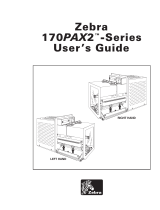
The Zebra 170PAX4 is a versatile printing solution capable of handling various media types, including non-continuous roll, continuous roll, and fanfold media. It supports both direct thermal and thermal transfer printing, making it suitable for a wide range of applications. The print engine can operate in either a right-hand or left-hand configuration, allowing for flexible integration into different setups.

The Zebra 170PAX4 is a versatile printing solution capable of handling various media types, including non-continuous roll, continuous roll, and fanfold media. It supports both direct thermal and thermal transfer printing, making it suitable for a wide range of applications. The print engine can operate in either a right-hand or left-hand configuration, allowing for flexible integration into different setups.

© 2004 ZIH Corp. All product names and numbers are Zebra
trademarks, and Zebra and the Zebra logo are registered
trademarks of ZIH Corp. All rights reserved.
57517L-002 Rev. A
6/28/07
170PAX4 Quick Reference Guide
This guide provides basic instructions to load and operate your print engine. For additional
information, refer to the User Guide.
Contents
Print Engine Exterior View . . . . . . . . . . . . . . . . . . . . . . . . . . . . . . . . . . . . . . . . . . . . . . . . . 2
Control Panel . . . . . . . . . . . . . . . . . . . . . . . . . . . . . . . . . . . . . . . . . . . . . . . . . . . . . . . . . . . 3
Control Panel Buttons . . . . . . . . . . . . . . . . . . . . . . . . . . . . . . . . . . . . . . . . . . . . . . . . . . 3
Control Panel Indicator Lights (LEDs) . . . . . . . . . . . . . . . . . . . . . . . . . . . . . . . . . . . . . . 4
Media . . . . . . . . . . . . . . . . . . . . . . . . . . . . . . . . . . . . . . . . . . . . . . . . . . . . . . . . . . . . . . . . . 5
Ribbon . . . . . . . . . . . . . . . . . . . . . . . . . . . . . . . . . . . . . . . . . . . . . . . . . . . . . . . . . . . . . . . . 6
Load Media . . . . . . . . . . . . . . . . . . . . . . . . . . . . . . . . . . . . . . . . . . . . . . . . . . . . . . . . . . . . 8
Load Ribbon. . . . . . . . . . . . . . . . . . . . . . . . . . . . . . . . . . . . . . . . . . . . . . . . . . . . . . . . . . . 16
Remove Used Ribbon . . . . . . . . . . . . . . . . . . . . . . . . . . . . . . . . . . . . . . . . . . . . . . . . . . . 22
Configure the Print Engine. . . . . . . . . . . . . . . . . . . . . . . . . . . . . . . . . . . . . . . . . . . . . . . . 23
Print a Configuration Label . . . . . . . . . . . . . . . . . . . . . . . . . . . . . . . . . . . . . . . . . . . . . 24
Print a Network Configuration Label . . . . . . . . . . . . . . . . . . . . . . . . . . . . . . . . . . . . . . 25
View or Change Parameters . . . . . . . . . . . . . . . . . . . . . . . . . . . . . . . . . . . . . . . . . . . . 26
Cleaning Schedule. . . . . . . . . . . . . . . . . . . . . . . . . . . . . . . . . . . . . . . . . . . . . . . . . . . . . . 30
Clean the Printhead and Platen Roller. . . . . . . . . . . . . . . . . . . . . . . . . . . . . . . . . . . . . 30
170PAX4 Quick Reference Guide
Print Engine Exterior View
2
57517L-002 Rev. A 170PAX4 Quick Reference Guide 6/28/07
Print Engine Exterior View
Print engines are available in a right-hand configuration (media moves from left to right,
Figure 27) and a left-hand configuration (media moves from right to left, Figure 28).
Figure 27 • Right-Hand (RH) Print Engine
Figure 28 • Left-Hand (LH) Print Engine
1
Media door
2
Control panel
3
Electronics cover
1
2
3
1
2
3
3
170PAX4 Quick Reference Guide
Control Panel
6/28/07 170PAX4 Quick Reference Guide 57517L-002 Rev. A
Control Panel
All controls and indicators for the print engine are located on the control panel (Figure 29).
The power switch is located to the side of the control panel.
Figure 29 • Control Panel (Right Hand)
Control Panel Buttons
The control panel buttons are described in Table 7.
1
Power switch
2
Buttons
3
Liquid Crystal Display (LCD)
4
Lights/LEDs
3 242
1
Table 7 • Control Panel Buttons
Button Description/Function
BLACK
OVALS
The two black ovals are used to change parameter values for a parameter being displayed
on the LCD. Common uses include increasing or decreasing a value, answering yes or no,
indicating ON or OFF, and scrolling through choices.
PREVIOUS Scrolls the LCD to the previous parameter.
NEXT Scrolls the LCD to the next parameter.
SETUP/EXIT Enters and exits configuration mode.
PAUSE Stops and restarts the printing process or removes error messages and clears the LCD. If a
label is printing, it is completed before the printing process stops. When the print engine is
paused, the PAUSE light is ON.
CANCEL
CANCEL functions only in Pause mode. Pressing CANCEL has these effects:
Cancels the label format that is currently printing.
If no label format is printing, the next one to be printed is canceled.
If no label formats are waiting to be printed,
CANCEL is ignored.
To clear the print engine’s entire label format memory, press and hold
CANCEL until the
DATA light turns off.
170PAX4 Quick Reference Guide
Control Panel
4
57517L-002 Rev. A 170PAX4 Quick Reference Guide 6/28/07
Control Panel Indicator Lights (LEDs)
The control panel lights are described in Table 8.
FEED Feeds a blank label.
If the print engine is idle or paused, the label is fed immediately.
If the print engine is printing, the label is fed after the current batch prints.
CALIBRATE
CALIBRATE functions only in Pause mode. Press CALIBRATE to recalibrate for proper
media length, to set media type (continuous/non-continuous), and to set print method
(direct thermal/thermal transfer).
Table 7 • Control Panel Buttons (Continued)
Button Description/Function
Table 8 • Control Panel Lights
LED
OFF Indicates ON Indicates FLASHING Indicates
POWER
(Green)
Print engine is
OFF, or no power
to print engine.
Power switch is ON, and power is being
supplied to print engine.
PAUSE
(Yellow)
Normal operation. One of the following:
Print engine is paused because of an
error condition (printhead, ribbon, or
paper error). Usually occurs in
conjunction with another LED.
PAUSE was pressed.
A pause was requested from the
Applicator Port.
A pause was received as part of the
label format.
DATA
(Green)
No data being
received or
processed.
Data is processing or printing is taking
place. No data is being received.
Print engine is receiving data
from or sending status
information to the host
computer.
MEDIA
(Yellow)
Normal operation.
Media properly
loaded.
Out of media. (Print engine is paused,
LCD displays error message, and
PAUSE light is ON).
RIBBON
(Yellow)
Normal operation.
Ribbon properly
loaded.
Ribbon in when print engine is in direct
thermal mode, or no ribbon in when print
engine is in thermal transfer mode. Print
engine is paused, LCD displays error
message, and PAUSE light is ON.
ERROR
(Orange)
No print engine
errors.
Print engine error exists.
Check the LCD for status.
5
170PAX4 Quick Reference Guide
Media
6/28/07 170PAX4 Quick Reference Guide 57517L-002 Rev. A
Media
The print engine can use various types of media (Table 9).
Table 9 • Types of Media
Media Type How It Looks Description
Non-Continuous Roll
Media
The media is wound on a core. Individual
labels are separated by a gap, notch, hole,
or black mark, which enables you to see
where one label ends and the next one
begins. When using media that has holes or
notches, position the media sensor directly
over a hole or notch.
Continuous
Roll Media
The media is wound on a core and is
without gaps, holes, notches, or black
marks. This allows the image to be printed
anywhere on the label.
Fanfold Media The media is folded in a zigzag pattern.
170PAX4 Quick Reference Guide
Ribbon
6
57517L-002 Rev. A 170PAX4 Quick Reference Guide 6/28/07
Ribbon
Ribbon is a thin film that is coated on one side with wax or wax resin, which is transferred to
the media during the thermal transfer process.
When To Use Ribbon
Thermal transfer media requires ribbon for printing while direct thermal media does not.
To determine if ribbon must be used with a particular media, perform a media scratch test.
To perform a media scratch test, complete these steps:
1. Scratch the print surface of the media with your fingernail.
2. Did a black mark appear on the media?
Coated Side of Ribbon
Ribbon can be wound with the coated side on the inside or outside (Figure 30). This print
engine can only use ribbon that is coated on the outside.
Figure 30 • Ribbon Coated on Outside or Inside
To determine which side of a ribbon is coated, complete these steps:
1. Peel a label from its liner.
2. Press a corner of the sticky side of the label to the outer surface of the roll of ribbon.
3. Peel the label off of the ribbon.
If a black mark... Then the media is...
Does not appear on the media Thermal transfer. A ribbon is required.
Appears on the media Direct thermal. No ribbon is required, though ribbon
may be used to help protect the printhead from
abrasion with the media.
Outside Inside
7
170PAX4 Quick Reference Guide
Ribbon
6/28/07 170PAX4 Quick Reference Guide 57517L-002 Rev. A
4. Observe the results. Did flakes or particles of ink from the ribbon adhere to the label?
If ink from the ribbon... Then...
Adhered to the label The ribbon is coated on the outer surface.
Did not adhere to the label The ribbon is coated on the inner surface. To verify this,
repeat the test on the inner surface of the roll of ribbon.
170PAX4 Quick Reference Guide
Load Media
8
57517L-002 Rev. A 170PAX4 Quick Reference Guide 6/28/07
Load Media
Figure 31 identifies the media-handling components of a right-hand print engine. A left-hand
unit contains a mirror image of these components. Figure 32 on page 9 shows both print
engines with media loaded.
Figure 31 • Components for Media Loading (Right-Hand)
1
Printhead latch
8
Media guide
2
Printhead assembly
9
Pinch roller assembly
3
Peel bar
10
Label guide shelf assembly
4
Platen roller
11
Lower guide post
5
Printhead locking pin
12
Upper guide post
6
Peel roller assembly
13
Top media sensor track assembly
7
Peel roller latch
1
2
589 6
3
4
12
11
710
13
9
170PAX4 Quick Reference Guide
Load Media
6/28/07 170PAX4 Quick Reference Guide 57517L-002 Rev. A
Figure 32 • Loaded Media
Left-Hand
Right-Hand
170PAX4 Quick Reference Guide
Load Media
10
57517L-002 Rev. A 170PAX4 Quick Reference Guide 6/28/07
To load media, complete these steps:
1. Load media on the media supply reel of the applicator (refer to the applicators user
guide).
2. Open the media door.
3. See Figure 33. Press down on the pinch roller release latch.
The pinch roller assembly springs up (Figure 34).
Figure 33 • Pressing the Pinch Roller Release Latch
Figure 34 • Opened Pinch Roller Assembly
Caution • When you are loading media or ribbon, remove all jewelry that could come into
contact with the printhead or other printer parts.
1
Pinch roller release latch
1
Pinch roller assembly
1
1
11
170PAX4 Quick Reference Guide
Load Media
6/28/07 170PAX4 Quick Reference Guide 57517L-002 Rev. A
4. See Figure 35. Under the print engine, grasp the brass thumb nut of the outer media guide,
and slide the outer media guide all the way out.
Figure 35 • Sliding the Outer Media Guide
1
Brass thumb nut
2
Outer media guide
1
2
170PAX4 Quick Reference Guide
Load Media
12
57517L-002 Rev. A 170PAX4 Quick Reference Guide 6/28/07
5. See Figure 36. Open the printhead assembly by unlatching the printhead latch from the
locking pin.
Figure 36 • Opening the Printhead Assembly
Caution • The printhead may be hot and could cause severe burns. Allow the printhead
to cool.
1
Printhead latch
2
Locking pin
1
2
13
170PAX4 Quick Reference Guide
Load Media
6/28/07 170PAX4 Quick Reference Guide 57517L-002 Rev. A
6. See Figure 37. Thread the media through the upper media path as follows:
a. Under the upper guide post
b. Between the top media sensor track assembly and the label guide shelf assembly
c. Below the pinch roller assembly
d. Under the printhead assembly
7. See Figure 37. Extend approximately 30 in. (75 cm) of media past the peel bar. Remove
and discard the labels from this exposed media.
Figure 37 • Threading the Media
1
Upper guide post
2
Top media sensor track assembly
3
Label guide shelf assembly
4
Pinch roller assembly
5
Printhead assembly
6
Peel bar
7
Liner
8
Label
1 4
5
7
2 3
6
8
170PAX4 Quick Reference Guide
Load Media
14
57517L-002 Rev. A 170PAX4 Quick Reference Guide 6/28/07
8. See Figure 38. Position the media so that it is aligned with and just touching the inner
media guide.
9. See Figure 38. Under the print engine, grasp the brass thumb nut of the outer media guide,
and position the outer media guide so that it just touches the outer edge of the media.
Figure 38 • Adjusting the Outer Media Guide
10. See Figure 33 on page 10. Press down on the pinch roller assembly until it locks closed.
11. See Figure 36 on page 12. Close the printhead assembly by rotating the printhead latch
until it latches onto the locking pin.
12. See Figure 39. Raise the peel roller latch so that the peel roller assembly pivots downward.
Figure 39 • Releasing the Peel Roller Assembly
1
Outer media guide
2
Media
1
Peel roller latch
2
Peel roller assembly
2
1
1
2
15
170PAX4 Quick Reference Guide
Load Media
6/28/07 170PAX4 Quick Reference Guide 57517L-002 Rev. A
13. See Figure 40. Thread the media liner around the peel bar, under the platen roller, and
through the peel roller assembly.
Figure 40 • Threading the Liner
14. See Figure 41. Rotate the peel roller assembly up until it locks into the closed position.
Figure 41 • Closed Peel Roller Assembly
15. See Figure 40. Thread the media liner under the lower guide post and around the take-up
spindle of the applicator (refer to the applicators user guide).
16. Close the media door.
Note • If the applicator has an air tube, route the media liner between the air tube and the
peel bar. Do not thread the media liner over the air tube.
1
Peel bar
2
Platen roller
3
Peel roller assembly
4
Lower guide post
1
2
3
4
170PAX4 Quick Reference Guide
Load Ribbon
16
57517L-002 Rev. A 170PAX4 Quick Reference Guide 6/28/07
Load Ribbon
Use ribbon with thermal transfer media (see Ribbon on page 6). The ribbon must be coated on
the outside and wider than the media. If the ribbon is narrower than the media, areas of the
printhead are unprotected and subject to premature wear.
Figure 42 identifies the ribbon system components inside the media compartment of a
right-hand print engine. A left-hand unit contains a mirror image of these components.
Figure 43 on page 17 shows the print engine with ribbon loaded.
Figure 42 • Components for Ribbon Loading
1
Ribbon supply spindle
5
Printhead assembly
2
Ribbon take-up spindle
6
Locking pin
3
Upper ribbon guide roller
7
Lower ribbon guide roller
4
Printhead latch
1 2
4
5
3
7
6
17
170PAX4 Quick Reference Guide
Load Ribbon
6/28/07 170PAX4 Quick Reference Guide 57517L-002 Rev. A
Figure 43 • Loaded Ribbon
Left-Hand
Right-Hand
170PAX4 Quick Reference Guide
Load Ribbon
18
57517L-002 Rev. A 170PAX4 Quick Reference Guide 6/28/07
To load ribbon, complete these steps:
1. See Figure 44. Place a full ribbon roll onto the ribbon supply spindle so the ribbon rotates
as shown, and then push the roll toward the print engine frame until it is fully seated.
Figure 44 • Placing Ribbon on the Ribbon Supply Spindle
Caution • When you are loading media or ribbon, remove all jewelry that could come into
contact with the printhead or other printer parts.
Left-Hand Right-Hand
1
Ribbon supply spindle with ribbon
1
1
19
170PAX4 Quick Reference Guide
Load Ribbon
6/28/07 170PAX4 Quick Reference Guide 57517L-002 Rev. A
2. See Figure 45. Open the printhead assembly by unlatching the printhead latch from the
locking pin.
Figure 45 • Opening the Printhead Assembly
3. See Figure 46. Thread the ribbon under the lower ribbon guide roller.
4. See Figure 46. Make sure that the ribbon passes directly below the ribbon sensor, which is
located near the back wall of the print engine.
Figure 46 • Threading Ribbon under the Ribbon Sensor
1
Printhead latch
2
Locking pin
1
Lower ribbon guide roller
2
Ribbon sensor
1
2
21
170PAX4 Quick Reference Guide
Load Ribbon
20
57517L-002 Rev. A 170PAX4 Quick Reference Guide 6/28/07
5. See Figure 47. Thread the ribbon under the printhead assembly and then around the upper
ribbon guide roller.
Figure 47 • Threading Ribbon under the Printhead Assembly
Caution • The printhead may be hot and could cause severe burns. Allow the printhead
to cool.
1
Upper ribbon guide roller
2
Printhead assembly
2
1
  • Page 1 1
  • Page 2 2
  • Page 3 3
  • Page 4 4
  • Page 5 5
  • Page 6 6
  • Page 7 7
  • Page 8 8
  • Page 9 9
  • Page 10 10
  • Page 11 11
  • Page 12 12
  • Page 13 13
  • Page 14 14
  • Page 15 15
  • Page 16 16
  • Page 17 17
  • Page 18 18
  • Page 19 19
  • Page 20 20
  • Page 21 21
  • Page 22 22
  • Page 23 23
  • Page 24 24
  • Page 25 25
  • Page 26 26
  • Page 27 27
  • Page 28 28
  • Page 29 29
  • Page 30 30
  • Page 31 31
  • Page 32 32

Zebra 170PAX4 Quick start guide

Category
Label printers
Type
Quick start guide

The Zebra 170PAX4 is a versatile printing solution capable of handling various media types, including non-continuous roll, continuous roll, and fanfold media. It supports both direct thermal and thermal transfer printing, making it suitable for a wide range of applications. The print engine can operate in either a right-hand or left-hand configuration, allowing for flexible integration into different setups.

Ask a question and I''ll find the answer in the document

Finding information in a document is now easier with AI