Page is loading ...

EV450RT
EV SERIES ERV
Installation, Operation and Maintenance Manual
Model: EV450RT shown

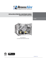
1.800.627.44992
EV-Series Outdoor
ERV
Three phase motors are NOT suitable for use with solid
state speed control.
Single phase EC motors are NOT suitable for use with solid
state speed control. They already have speed control built
into the motor electronics.
WARNING
Moteurs de trois phase ne convient pas pour utilisation avec
regulateur de vitesse electronique.
Moteurs d’une phase de l’EC ne conviennent pas pour une
utilisation avec regulateur de vitesse electronique. Ils ont
déjà le contrôle de vitesse intégré dans le moteur électro-
nique.
AVERTISSEMENT
RISK OF INJURY OR DAMAGE.
Motor may have a manual reset thermal protector. Dis-
connect power before servicing or resetting motor thermal
protector. Use caution, motor may be hot. Allow the motor
to cool before resetting the thermal protector.
If the motor thermal protector tripped, correct the issue that
caused the motor to overheat (e.g. over motor rated amper-
age or locked rotor).
If the motor has a manual reset thermal protector, the red
thermal protector reset button is located on the motor body,
on or near the lead end of the motor. If the button does not
reset, the motor may still be too hot. Allow the motor to fully
cool to reset the thermal protector, you should feel or hear
a click when the thermal protector resets while pushing the
reset button.
WARNING
ARC FLASH AND ELECTRIC SHOCK HAZARD
Arc flash and electric shock hazard. Disconnect all electric
power supplies, verify with a voltmeter that electric power
is off and wear protective equipment per NFPA 70E before
working within electric control enclosure. Failure to comply can
cause serious injury or death.
Customer must provide earth ground to unit, per NEC, CEC and
local codes, as applicable.
Before proceeding with installation, read all instructions,
verifying that all the parts are included and check the
nameplate to be sure the voltage matches available utility
power.
The line side of the disconnect switch contains live high-
voltage.
The only way to ensure that there is NO voltage inside the unit
is to install and open a remote disconnect switch and verify
that power is off with a volt meter. Refer to unit electrical
schematic.Follow all local codes.
WARNING
RISK OF ELECTRIC SHOCK OR EQUIPMENT DAMAGE
Whenever electrical wiring is connected, disconnected or
changed, the power supply to the ERV and its controls must
be disconnected. Lock and tag the disconnect switch or circuit
breaker to prevent accidental reconnection of electric power.
CAUTION
RISK OF CONTACT WITH HIGH SPEED MOVING PARTS
Disconnect all local and remote power supplies, verify with
a voltmeter that electric power is off and all fan blades have
stopped rotating before working on the unit.
Do not operate this unit with any cabinet panels removed.
CAUTION
This equipment is to be installed by following industry best
practices and all applicable codes. Any damage to compo-
nents, assemblies, subassemblies or the cabinet which is
caused by improper installation practices will void the
warranty.
IMPORTANT
This unit is for ventilating finished structures only. It is not to
be used until after all construction has been completed and
construction debris and dust are cleaned from the Occupied
Space.
IMPORTANT
This unit is intended for general ventilating and heating only.
Do not use to exhaust hazardous or explosive materials and
vapors. Do not connect this equipment to range hoods, fume
hoods or collection systems for toxics.
IMPORTANT

31.800.627.4499
EV-Series Outdoor ERV
OWNER INFORMATION
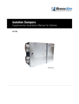
UNIT INFORMATION
Record information as shown below.
In the unlikely event that factory assistance is ever required, information located on the unit
label will be needed.
Locate the RenewAire unit label found on the outside of the unit.
NOTE: This information is for purposes of identifying the unit-specific option data from the
Option Code.
E-
04 RV -
J5 T -
Option Code:
Serial Number:
SO #:
NOTE: This page
is to be completed
by the installing
contractor. The completed
document is to be turned
over to the owner after
start up.
SO#: 074704
JO#: 43848-0000
208-230V
Option Code: EV450JRT--D15E----GNT---L
Serial Number:
MODEL/MODELE:
1
[email protected] 4.8 6.0
Energy Recovery Ventilator
Label No:
130137_000_D03
15
EV450RT
A20 7889C
UNIT INFORMATION
UNIT LABEL (TYPICAL)
This manual contains space for maintaining written records of unit maintenance and/
or repairs. See Section 7.7 Maintenance Records. At the time the ERV is commissioned, a
maintenance schedule should be developed by the user to incorporate monthly and seasonal
maintenance and include start-up maintenance tasks as described in this manual.
NOTICE
READ AND SAVE THIS MANUAL/LIRE ET CONSERVER CE MANUEL

1.800.627.44994
Subject to change without notice: RENEWAIRE.COM | 1.800.627.4499 98 Subject to change without notice: RENEWAIRE.COM | 1.800.627.4499
SPECIFICATIONS & DIMENSIONS
HP Volts HZ Phase FLA
Min.
Cir.
Amps
Max.
Overcurrent
Protection
Device
0.6 120 60 Single 7.2 9.0 15
0.6 208-230 60 Single 3.9-3.6 4.9 15
0.6 277 60 Single 3.5 4.4 15
0.5 208-230 60 Three 1.7-1.5 2.1 15
0.5 460 60 Three 0.8 1.0 15
ELECTRICAL DATA UNIT PERFORMANCE
Airflow CFM ESP in H20Watts
1P 3P
240 1.00 425 243
375 0.75 493 341
450 0.50 534 412
500 0.25 563 461
550 0.00 593 516
Note: Watts is for the entire unit.
Note: Airflow performance includes effect of clean, standard filter supplied with unit.
450RTEV Energy Recovery Ventilator
Standard
ROOFTOP UNIT SPECIFICATIONS
Ventilation Type:
Static plate, heat and humidity transfer
Typical Airflow Range: 240-500 CFM
AHRI 1060 Certified Core: One L85-G5
Standard Features:
Non-fused disconnect
24 VAC transformer/relay package
Filters:
Total qty. 2, MERV 8: 14" x 20" x 2"
Unit Weight:
184-243 lbs., varies by option(s)
Max. Shipping Dimensions & Weight (on pallet):
96" L x 47" W x 25" H
350 lbs.
Motor(s), choice of:
Qty. 1, 0.6 HP (standard single phase)
Qty. 1, 0.5 HP (standard three phase)
Options:
Qty. 1, Variable Speed/ECM - Direct Drive Motors
(see EV450IN EC Motor submittal) -
0.5 HP, 120V/1Ph/60HZ,
0.5 HP, 208-230V/1Ph/60HZ
Fused disconnect
Integrated programmable controls -
enhanced, premium
Qty. 2, Factory mounted filter alarms -
both airstreams
Double wall construction
Exterior paint - white, custom colors
Accessories:
Filters - MERV 13, 2" (shipped loose)
Automatic balancing damper - 4", 5", 6"
Solid state speed control kit - 115V, qty. 1,
208-230V, qty. 1
RA/FA Horizontal plenum box - RTC/RTH configuration
RA/FA Vertical and horizontal plenum box
- RTR/RTF configuration
Rooftop adapter transition paint - white, custom colors
Roof curb - standard 14"
Curb wind clip
Engineered combo curb for Carrier RTU
Engineered combo curb for Trane RTU
Digital time clock - wall mount (TC7D-W),
in exterior enclosure (TC7D-E)
Carbon dioxide sensor/control -
wall mount (CO2-W), duct mount (CO2-D)
IAQ sensor - wall mount (IAQ-W),
duct mount (IAQ-D)
Motion occupancy sensor/control -
ceiling mount (MC-C), wall mount (MC-W)
Smoke detector - duct mount (SD-D)
Electric duct heater - EK series (1–175 kW);
designed for indoor ductwork installation only
Note: Indirect Gas-Fired Duct Furnace is not available on the EV450RT.
Energy Recovery Core is AHRI Certified®
Specifications may be subject
to change without notice.

51.800.627.4499
Subject to change without notice: RENEWAIRE.COM | 1.800.627.4499 98 Subject to change without notice: RENEWAIRE.COM | 1.800.627.4499
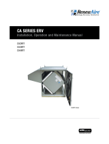
SPECIFICATIONS & DIMENSIONS
EA OA
FA
14 1/4" Minimum
Service Area
(Door can be
Removed from
Hinges)
48 3/8" Minimum
Service Area
46"
12 1/4"
22 3/4"
31 3/8"
3"
Version: JUL17
Drawing Type: Unit Dimension
Model: EV450RT
ABBREVIATION
EA: Exhaust Air to outside
OA: Outside Air intake
RA: Room Air to be exhausted
FA: Fresh Air to inside
INSTALLATION ORIENTATION
Unit must be installed in orientation
shown.
NOTE:
1. UNLESS OTHERWISE SPECIFIED,
DIMENSIONS ARE ROUNDED TO THE
NEAREST EIGHTH OF AN INCH.
2. SPECIFICATIONS MAY BE SUBJECT
TO CHANGE WITHOUT NOTICE.
Bottom of Unit
FRONT VIEW
Disconnect
Switch
Swing
Door
(2) 7/8" Holes
for Wiring in
RA
C
L
44 5/8" Lifting Lugs
4 1/8" Control In
C
L5 1/4" Power In
5 1/2" X 6 1/4"
FA Opening
TOP VIEW
RA Opening
11 3/4" X 13"
(Triangular)
74 3/4" Overall
48 7/8" Case 11 3/4"
RIGHT VIEW
C
L
34 1/4" Case
36 1/2" Overall
4 7/8" Control In
C
L4 1/4" Power In
LEFT VIEW
Overall
Lifting Lugs
19 1/4" Case
30 5/8"
19 1/4"
1 5/8"
Typ.
CURB CROSS-SECTION A-A (TYP.)
SECTION
1 1/2" X 1/4"
Neoprene Gasket
A-A
3/4" X 3 1/2"
Wooden Nailer
3"
1 7/8"
14"
FA
TOP VIEW
CURB EV450
RA
41 5/8" I.D.
45 3/8" O.D.
13"
27 1/2" I.D.
12 5/8" 16 1/2" 12 5/8"
31 1/4" O.D.
A
A
AIRFLOW CONFIGURATION
Available as shown in dimension drawing.
UNIT MOUNTING & APPLICATION
Must be mounted as shown. Airstreams can not
be switched. Rooftop adapter accessories can be
used to provide RTR and RTF (45RTRF) or RTH and
RTC (45RTCH) airflow.
EV450RT Energy Recovery Ventilator Standard or EC Motor OptionEV450RT Energy Recovery Ventilator Standard or EC Motor Option
Standard
Specifications may be subject
to change without notice.

1.800.627.44996
EV-Series Outdoor
ERV
TABLE OF CONTENTS
5.5 EXTERNAL CONTROL CONNECTIONS .....................17
5.5.1 Single 2-Wire Control, Unpowered ..................................... 17
5.5.2 Control Sending 24 VAC “On” Signal ................................. 17
5.5.3 Control Operating on Unit's 24 VAC Power Supply ..............17
5.6 QUICK START FOR TESTING CORRECT 3 PH WIRING
..................................................................................18
6.0 OPERATION 18
6.1 PRINCIPLE OF OPERATION ....................................18
6.2 PRE-START-UP .....................................................18
6.2.1 Verify Voltages .................................................................. 18
6.2.2 Verify Transformer Wiring ................................................. 18
6.2.3 Inspect Filters ..................................................................18
6.2.4 Inspect Foam Gasketing .................................................... 18
6.2.5 Inspect Fans ..................................................................... 18
6.2.6 Inspect and Clean the Cabinet Interior ...............................18
6.2.7 Inspect Ductwork Connections ..........................................18
6.3 UNIT START-UP ....................................................19
6.3.1 Fixed Speed Units ............................................................. 19
6.4 FILTER PRESSURE DROP .......................................19
6.5 NORMAL OPERATION ............................................20
6.6 EXTREME COLD OPERATION .................................20
7.0 MAINTENANCE 20
7.1 MAINTENANCE 24 HRS. AFTER START-UP .............20
7.2 MAINTENANCE 30 DAYS AFTER START-UP .............20
7.3 MAINTENANCE SCHEDULE .................................... 20
7.4 FILTERS ...............................................................21
7.5 FAN MOTOR ..........................................................21
7.6 ENTHALPIC CORE .................................................21
7.6.1 Enthalpic Core Maintenance ..............................................21
7.6.2 Enthalpic Core Removal ....................................................21
7.6.3 Enthalpic Core Rempacement ............................................21
7.7 MAINTENANCE RECORDS .....................................22
7.8 SERVICE PARTS .................................................... 23
8.0 TROUBLESHOOTING 23
9.0 FACTORY ASSISTANCE 23
1.0 OVERVIEW 8
1.1 DESCRIPTION .........................................................8
2.0 COMPNENT DESCRIPTIONS 8
2.1 CABINET ................................................................8
2.2 ENTHALPIC CORES .................................................8
2.3 FAN/MOTOR ASSEMBLIY ......................................... 9
2.4 E-BOX ....................................................................9
2.5 FILTERS .................................................................9
2.6 FACTORY INSTALLED OPTIONS ................................9
3.0 SHIPPING/RECEIVING/HANDLING 9
3.1 UNIT WEIGHTS AND DIMENSIONS ...........................9
3.1.1 Unit Dimensions and Weight ................................................9
3.1.2 Maximum Shipping Dimensions and Weight (on pallet) .........9
3.2 RIGGING AND CENTER OF GRAVITY .......................10
3.2.1 EV450RT Hoisting Weights and COG .................................. 10
3.3 RECIEVING ...........................................................10
3.4 HANDLING AND STORAGE .....................................10
4.0 UNIT PLACEMENT 10
4.1 BEFORE YOU BEGIN ..............................................10
4.2 SERVICE CLEARANCES .........................................11
4.3 SOUND ATTENUATION ...........................................11
4.3.1 Outside the Building .......................................................... 11
4.3.2 At the Curb ....................................................................... 11
4.3.3 Ducts ............................................................................... 11
4.3.4 Radiated Noise ................................................................. 12
4.3.5 Aerodynamic (Velocity) Noise ............................................ 12
5.0 INSTALLATION 12
5.1 CURB SPECIFICATIONS .........................................12
5.2 DUCTWORK ..........................................................13
5.2.1 Connecting Ducts to Unit ...................................................13
5.2.2 Duct Layout Options ......................................................... 13
5.3 ELECTRICAL REQUIREMENTS ................................ 14
5.3.1 Electronically Commutated Motors .................................... 14
5.3.2 Power Supply ...................................................................14
5.3.3 Low Voltage Control System ............................................. 14
5.3.4 How to Reset the 24 VAC Circuit Breaker ........................... 15
5.3.5 Limits of Power Output ..................................................... 15
5.4 WIRING SCHEMATICS............................................16

71.800.627.4499
EV-Series Outdoor ERV
TABLE OF CONTENTS
TABLE OF ILLUSTRATIONS
MODEL NUMBER
1 2 3 4 5 6 7 8 9 10 11 12 13 14 15 16 17 18 19 20 21 22 23 24 25
J - - -
DIGIT NUMBER
Wall Type
Digit 11:
"S" = Single
"D" = Double
Phase
Digit 12:
"1" = Single Phase
"3" = Three Phase
Voltage
Digit 13:
"1" = 115V
"4" = 460V
"5" = 208-230V
"9" = 277V
FA/EA Horsepower
Digit 14:
"-" = Standard EV450 Motors
"E" = EC Direct Drive Motors
*NOTES:
Digit 6 "J" = G5 Core Type Digits 9,10, 15, 16, 17 & 18 are not used in these models.
Restrictions:
1: Voltage Codes "1" & "9" only available with Phase Code "1" (Single-Phase).
2: Voltage Codes "4" & "8" only available with Phase Code "3" (Three-Phase).
3: Motor Code "E-" (EC Motors) only available with Phase Code "1" (Single Phase)
4: Unit Control Code "G" (Terminal Strip) only available with Motor Code "E-".
5: Some units with Customization Code "X" are not safety listed.
Unit Control
Digit 19:
"A" = Standard Unit Control Wiring
"G" = Terminal Strip for EC Motors
Disconnect
Digit 20:
"N" = Non-Fused (STANDARD)
"F" = Fused
Unit Control Enhancements
Digit 21:
"T" = Transformer with Isolation Relay (STANDARD)
"1" = Enhanced Controls
"2" = Premium Controls
"3" = Enhanced Controls with BACNET License
"4" = Premium Controls with BACNET License
Filter Options
Digit 22:
"-" = None
"F" = Filter Monitor Both Airstreams
Other Options
Digit 23:
"-" = None (Reserved)
Paint and Customization
Digit 24:
"-" = None
"W" = White Paint
"C" = Custom Paint
"X" = Custom Unit
Safety Listing
Digit 25:
"L" = Listed
"N" = Non-Listed
-EV450 RT - - -
EV450RT MODEL
PRODUCT CODE CHART
CONFIGURATION CODE
Figure 3.2.0 EV450RT Weights and COG ...........................................................................................10
Figure 4.2.0 Service Clearances, Top View ........................................................................................ 11
Figure 5.1.0 RTR/RTF Configuration, RTR Shown ...............................................................................12
Figure 5.1.1 RTC/RTH Configuration ..................................................................................................13
Figure 5.4.0 EV450 Single Pase Unit Power Wiring Schematic ...........................................................16
Figure 5.4.1 EV450 Three Pase Unit Power Wiring Schematic ............................................................16
Figure 5.5.0 A Switch or Non-Powered Control Using Unit's 24 VAC Power Supply.............................. 17
Figure 5.5.1 24 VAC from an External Source .................................................................................... 17
Figure 5.5.2 An External Control Device using Unit's 24 VAC Power Supply ........................................ 17
Figure 6.4.0 Initial Pressure Drop of MERV 8 Filters, Supplied with this Unit .......................................19
Figure 6.4.1 Initial Pressure Drop of MERV 13 Filters, Available as an Accessory ................................19
Figure 7.8.0 Service Parts.................................................................................................................23

1.800.627.44998
EV-Series Outdoor
ERV
1.0 OVERVIEW
OVERVIEW
NOTE: This unit is
an Energy Recovery
Ventilator, or ERV.
It is commonly referred to
throughout this manual as
an ERV.
1.1 DESCRIPTION
2.0 COMPONENT DESCRIPTIONS
2.2 ENTHALPIC CORES
2.1 CABINET
All EV450RT ERVs use a static-plate enthalpic core. The enthalpic cores transfer both latent and
sensible energies between the airstreams. Cores are bi-directional and may be rotated in their
mounting hardware, but care must be taken to install the correct side of the core toward the
unit door. Gasketing is pre-installed on the cores and must be positioned to provide a proper air
The cabinet for the EV450RT is made of 20 gauge galvanized steel and has 1" thick high-
density, foil-backed insulation on the inside. Units are available in either single-wall or double-
wall construction. Doors are hinged and are fitted with stainless steel machine screws through
the faces to prevent accidental opening of the doors when the unit is in operation. Doors may be
completely removed by removing the hinge pins. All units are equipped with adjustable-height
leveling legs for purposes of leveling the unit. Duct flanges are provided at all four airstream
openings for connection of field-supplied ductwork.
The EV450RT Energy Recovery Ventilator is a device for recovering both sensible energy (heat) and
latent energy (moisture) from the Exhaust Air from an Occupied Space and injecting those energies
into an incoming Outside Air stream. It accomplishes this task by forcing the two airstreams through
enthalpic cores, where the energy exchange takes place. The two airstreams pass through the
enthalpic cores at right angles and the airstreams never mix together. See Section 2.2 Enthalpic
Cores in this manual.
Each ERV has two electric blowers, one for each airstream. Fan speeds can be either single speed,
using adjustable sheaves to change fan speed, or they can have electronically commutated motors
There are a number of different control devices available to control the operation or speed of the unit
fans.
There are two types of EV450 units, one for indoor installations and one for rooftop, or outdoor,
installation. This manual is for the EV450RT, which is the outdoor unit. For information on the indoor
version of this product, see the EV450IN Installation and Operation Manual.
EV450RT units are designed to be installed outdoors, mounted on either a factory-supplied curb or
on owner-supplied rails.
These ERVs are commonly installed as part of an air handling system that provides heating and
cooling of Supply Air. They can also be installed to operate as stand-alone devices when ducted
directly to and from the Occupied Space.
Each unit has an integral 24 VAC power supply that is used internally and can also be used as a
power source for other optional control devices.
The EV450RT units are low-maintenance, requiring periodic replacement of the air filters and
annual vacuuming of the enthalpic cores. See Section 7.0 Unit Maintenance in this manual.
IMPORTANT
It is important to understand and use the equipment airstream terminology as it is used in this
manual. The airstreams are defined as:
u OUTSIDE AIR (OA): Air taken from the external atmosphere and, therefore, not previously
circulated through the system.
u FRESH AIR (FA): Air that is downstream of the enthalpic cores and is ready for conditioning or
for return to the Occupied Space.
u RETURN AIR (RA): Air that is returned to the ERV from a conditioned space.
u EXHAUST AIR (EA): Air that is removed from a heating or cooling appliance or from the Occu-
pied Space and discharged.

91.800.627.4499
EV-Series Outdoor ERV
SHIPPING/RECEIVING
2.3 FAN/MOTOR ASSEMBLY
2.4 E-BOX
Every EV450RT is equipped with what is known as an “E-Box.” High-voltage supply wiring and
low-voltage control wiring is all terminated here. If optional integrated programmable controls
are installed, an additional 24 VAC transformer is installed here to power both the controller and
its dedicated sensors.
2.5 FILTERS
All EV450RT units come equipped with two MERV 8 14" x 20" x 2" (nominal) pleated filters.
MERV 13 filters can be ordered as an accessory and are shipped loose.
u (2) 14" x 20" x 2" (nominal) pleated filters. Actual size: 13.5" x 19.5" x 1.75"
u Minimum recommended effectiveness: MERV 6.
2.6 FACTORY INSTALLED OPTIONS
All EV450RT units can be ordered with factory installed options. See Unit Configuration Code on
page 7.
Options will have supplemental manuals shipped with the unit.
For EC Motor option, see EC Motor Supplemental Manual.
For Commercial Controls, see Commercial Controls Supplemental Manual.
For Filter Alarm, see Filter Alarm Supplemental Manual.
A single motor with manual reset thermal protection directly drives two fans for quiet operation.
3.0 SHIPPING/RECEIVING/HANDLING
EV450RT units are palletized at the factory and then shipped by common carrier. Upon receipt
by the installer, the shipment should be inspected for shipping damage, prior to unloading. Any
discovered shipping damage should be immediately reported to the RenewAire sales rep and the
damage must be recorded on the Bill Of Lading, prior to signing for acceptance of the shipment.
The unit can be handled with a forklift or a crane. Prior to moving the unit, verify that all latches
and securing bolt on the cabinet door are tightly fastened.
If a crane is used for moving the EV450RT unit, use slings or shackles at all four corners
to hoist the unit; spreader bars are recommended in order to avoid damage to the unit. The
hoisting slings must be positioned around the ends of the unit so they do not touch the unit
door. Unit hoisting weights and Center of Gravity are detailed in Section 3.1 Unit Weights and
Dimensions in this manual.
Perform a test lift to make sure the unit is being hoisted level and is secure.
Place the EV450RT unit on a flat surface where it will be protected from the weather and
incidental damage. Do not remove protective coverings from any duct openings and keep the
door secured and tightly closed.
3.1 UNIT WEIGHTS AND DIMENSIONS
3.1.1 Unit Dimensions and Weight:
75" L x 36 1/2" W x 19 1/4" H
184-243 lbs., varies by option(s)
3.1.2 Maximum Shipping Dimensions and Weight (on pallet):
96" L x 47" W x 25" H
350 lbs.
seal. For information on annual maintenance of the cores, see Section 7.0 Maintenance in this
manual.

1.800.627.449910
EV-Series Outdoor
ERV
UNIT PLACEMENT
12/8/06 MF
SPECIFICATIONS SUBJECT
TO CHANGE WITHOUT NOTICE.
RenewAire LLC
Scale: 1" = 24"
Do not scale drawing
EV450RT_CORNER_WEIGHTS_MAR20.dwg
EV450RT Corner Weights
12/30/15 KMC; uppdated corner labels
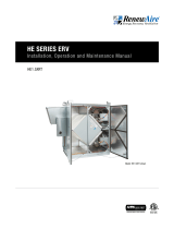
BASIC UNIT WEIGHTS (lbs.)
Motors UNIT LF LR RR RF
1-PHASE (.6 HP) 184 53 48 39 44
3-PHASE (.5 HP) 188 54 50 50 44
ADDITIONAL WEIGHTS FOR OPTIONS (lbs.)
Options UNIT LF LR RR RF
Double Wall 55 14 15 14 12
Total Selected Weights
INDICATES LOCATIONS AT WHICH CORNER WEIGHTS ARE
CALCULATED: ALONG CENTERS OF CURB RAILS.
Center of gravity: From Left (A) = 20", From Front (B) = 15" (+/- 2")
JUN18 MHK
LF RF
LR RR
43.500"
A
29.375"
B
UNIT COG
RANGE
MAR20 KMC
FIGURE 3.2.0 EV450RT WEIGHTS AND COG
3.2 RIGGING AND CENTER OF GRAVITY
3.3 RECEIVING
Upon receipt of the EV450RT, inspect the unit for obvious external damage. If damage is
observed, take digital pictures and report the damage to your RenewAire rep. Note the damage
on the carrier’s Bill of Lading. Depending on expected transport and storage conditions, the
unit may have only the duct openings covered, it may be stretch-wrapped or it may be crated.
Do not unwrap the unit at this time. The unit will normally be moved to its final location while
still wrapped and attached to its pallet. The preferred method of hoisting the EV450RT from the
carrier truck is by using a construction forklift.
Once the unit is unwrapped, prevent dirt and debris from entering the cabinet by covering any
duct openings. Keep the duct openings covered until it is time to connect ductwork.
3.4 STORAGE
Units that must be stored prior to installation should be left on their pallets and protected from
weather and physical damage. Units must be placed on a level surface to prevent wracking of
the pallet and the EV450RT. The access door must be secured with all available hardware (door
latches and securing bolt) and all openings into the cabinet must be sealed to prevent entry of
dust, dirt and debris.
4.0 UNIT PLACEMENT
4.1 BEFORE YOU BEGIN
The EV450RT is designed for installation outdoors, typically on a roof top. The preferred
mounting method is to place the ERV on an optional manufactured curb, designed for the
specific unit. RenewAire recommends the use of optional curb clips to provide substantial
resistance to wind damage.
For all installations, maintain needed service clearances as shown on the dimensioned drawings
located in Section 4.2 of this manual. The curb should be placed on the completed roof decking
and located so that the entire perimeter of the curb rests directly on or above structural steel
roof supports.
3.2.1 EV450RT Hoisting Weights and COG

111.800.627.4499
EV-Series Outdoor ERV
UNIT PLACEMENT
4.2 SERVICE CLEARANCES
FIGURE 4.2.0 SERVICE CLEARANCES, TOP VIEW
EA OA
FA
14 1/4" Minimum
Service Area
(Door can be
Removed from
Hinges)
48 3/8" Minimum
Service Area
46"
12 1/4"
22 3/4"
31 3/8"
3"
Version: JUL17
Drawing Type: Unit Dimension
Model: EV450RT
ABBREVIATION
EA: Exhaust Air to outside
OA: Outside Air intake
RA: Room Air to be exhausted
FA: Fresh Air to inside
INSTALLATION ORIENTATION
Unit must be installed in orientation
shown.
NOTE:
1. UNLESS OTHERWISE SPECIFIED,
DIMENSIONS ARE ROUNDED TO THE
NEAREST EIGHTH OF AN INCH.
2. SPECIFICATIONS MAY BE SUBJECT
TO CHANGE WITHOUT NOTICE.
Bottom of Unit
FRONT VIEW
Disconnect
Switch
Swing
Door
(2) 7/8" Holes
for Wiring in
RA
C
L
44 5/8" Lifting Lugs
4 1/8" Control In
C
L5 1/4" Power In
5 1/2" X 6 1/4"
FA Opening
TOP VIEW
RA Opening
11 3/4" X 13"
(Triangular)
74 3/4" Overall
48 7/8" Case 11 3/4"
RIGHT VIEW
C
L
34 1/4" Case
36 1/2" Overall
4 7/8" Control In
C
L4 1/4" Power In
LEFT VIEW
Overall
Lifting Lugs
19 1/4" Case
30 5/8"
19 1/4"
1 5/8"
Typ.
CURB CROSS-SECTION A-A (TYP.)
SECTION
1 1/2" X 1/4"
Neoprene Gasket
A-A
3/4" X 3 1/2"
Wooden Nailer
3"
1 7/8"
14"
FA
TOP VIEW
CURB EV450
RA
41 5/8" I.D.
45 3/8" O.D.
13"
27 1/2" I.D.
12 5/8" 16 1/2" 12 5/8"
31 1/4" O.D.
A
A
The EV450RT weighs approximately 243 lbs. It is the installer’s responsibility to make sure
that the screws or bolts used for securing the units are properly selected for the loads and
substrates involved. Secure the EV450RT so that it cannot fall or tip in the event of accident,
structural failure or earthquake.
RenewAire strongly recommends that you secure rooftop units properly to the building
structure. Strong winds, tornados, and hurricanes can and do displace or remove rooftop
equipment from rails or curbs. When this happens, the equipment, adjacent roof structure,
and even vehicles parked near the building can be damaged, and rain typically enters
the building. The equipment is put out of service and the collateral damage can be very
expensive.
CAUTION
4.3 SOUND ATTENUATION
Take these simple steps to attenuate noise from the unit.
4.3.1 Outside the Building
The exhaust hood is the primary source of noise outside the building. When practical, orient the
exhaust air hood to point away from houses or public areas.
Cut the holes in the roof deck to fit closely around the duct(s) passing through the roof deck. Seal all gaps
around the duct(s) at the roof deck.
4.3.2 At the Curb
Cut the holes in the roof deck to fit closely around the duct(s) passing through the roof deck.
Seal all gaps around the duct(s) at the roof deck.
4.3.3 Ducts
Make sure the ductwork at the unit outlets is stiff enough to resist the flexure and resulting
booming associated with system start-up and shut-off, as well as the turbulent flow conditions
at the blower outlets.
In general, provide smooth transitions from the ERV’s outlets to the duct. The ducts connecting
to the outlets should be straight for a sufficient distance, with gradual transitions to the final
duct size.
These guidelines are consistent with SMACNA recommended duct layout practices for efficient
and quiet air movement. Follow SMACNA guidelines.

1.800.627.449912
EV-Series Outdoor
ERV
INSTALLATION
4.3.4 Radiated Noise
The EV450RT is insulated with high-density fiberglass. This provides significant attenuation of
radiated sound from the unit itself.
The outlet ducts can be significant sources of radiated sound as well. The FA duct should be
insulated for sound control. This insulation should start at the unit. At a minimum the first ten
feet of duct should be insulated. All parts of the FA and RA ducts located in a mechanical space
with noise-generating equipment also should be insulated for sound control, both to minimize
sound radiation out of the FA duct, and also to control sound radiation into both ducts.
4.3.5 Aerodynamic (Velocity) Noise
When sound attenuation is a design concern, the primary consideration is velocity noise at the
unit’s FA blower outlet. The average velocity at the blower outlet is 2800 FPM when the unit is
operating at 450 CFM. The average velocity at the Exhaust Hood outlet is 1370 FPM when the
unit is operating at 450 CFM.
5.0 INSTALLATION
5.1 CURB SPECIFICATIONS
For all rooftop curbs, the curb is to be placed in a location specified by the Architect/Engineer
as being capable of supporting all known loads. Curbs are to be installed using Industry Best
Practices. For installation guidelines, see the current National Roofing Contractors Association
(NRCA) manuals.
For metal roofs that are supported by structural steel, the supporting structural steel must
be located so that it supports the entire perimeter of the curb. Ideally, the curb will be placed
directly on the structural steel and the metal roof decking is to be fitted around the curb. It
is acceptable to place the metal roof decking on the structural steel and then place the curb
on top of the metal roof decking. When this is done, wood fillers must be installed in the
decking corrugations to provide complete support for the curb bottom flanges. In all cases, all
four bottom flanges of the curb must bear directly on or over the structural steel roof
supports.
For pre-stressed concrete roofs, the location of the curb must be approved by an engineer as
being capable of supporting all known loads.
Curbs are shipped knocked-down and include all necessary assembly hardware, to include
foam gasketing tape. To assemble the curb, assemble the four sides of the curb with the
provided hardware, but leave the hardware loose. When the four curb sides are assembled,
install the provided mid-rails within the curb walls and then tighten all fasteners. See Dimension
Drawings on page 5 for curb dimensions.
Curb clips are available as an optional accessory and can be installed as needed. Install foam
gasketing (provided) on all bearing surfaces on the curb.
The RTF/RTR Adapter Accessory allows horizontal connection of either the Fresh Air duct or
the Return Air duct, stack the RTF/RTR Adapter Accessory on the Standard Roof Curb. Duct
openings to be field cut into adapter. Opening location and size is flexible.
28"
FA
28" RA
EV450RT WITH RTF/RTR ADAPTER
(45RTRF) AND CURB (45CURB)
IN RTF CONFIGURATION
EV450RT WITH RTF/RTR ADAPTER
(45RTRF) AND CURB (45CURB)
IN RTR CONFIGURATION
FA
ROOF CURB
ADAPTER (FULLY
INSULATED)
EV450RT
OA
EA
EA OA
RTR/RTF
14"
RA
MATERIAL:
FINISH:
LINEAR ±
HOLE SIZE ±
< ±
SURFACE FINISH
UNLESS OTHERWISE SPECIFIED, DIMENSIONS
AND TOLERANCES ARE IN INCHES.
4510 Helgesen Dr.
Madison, WI 53718 USA
FAX: (608) 221-2824
TEL: (608) 221-4499
SIZE:
TOLL FREE: (800) 627-4499
CHECKED BY: DATE:
DRAWN BY: DATE:
RenewAire
DO NOT SCALE DRAWING. REMOVE
ALL BURRS. BREAK SHARP EDGES.
APPLICABLE STANDARDS: DIM. AND
TOL. ANSI Y14.5
TITLE:
DRAWING NO.
SCALE:
REVISION
SHEET:
LEVEL DESCRIPTION DATE BY
KWE 4-16-02
--
450RT_adaptcurb_DIMS_MAY1
6
1/42 A 2 OF 3
SEE BILL OF MATERIALS
_
MAY16 REFORMAT 5/20/16 KMC
63
.015
.005
450RT ADAPTER CURB DIMENSIONS
3 DEG
FIGURE 5.1.0 RTR/RTF CONFIGURATION, RTR SHOWN

131.800.627.4499
EV-Series Outdoor ERV
INSTALLATION
17 1/2" 46"
15 1/2"
FA RA
38"
EV450RT WITH ADAPTER (45RTCH)
EA OA
ADAPTER (FULLY
INSULATED)
RTC/RTH
OA
RA
FA
MATERIAL:
FINISH:
LINEAR ±
HOLE SIZE ±
< ±
SURFACE FINISH
UNLESS OTHERWISE SPECIFIED, DIMENSIONS
AND TOLERANCES ARE IN INCHES.
4510 Helgesen Dr.
Madison, WI 53718 USA
FAX: (608) 221-2824
TEL: (608) 221-4499
SIZE:
TOLL FREE: (800) 627-4499
CHECKED BY: DATE:
DRAWN BY: DATE:
RenewAire
DO NOT SCALE DRAWING. REMOVE
ALL BURRS. BREAK SHARP EDGES.
APPLICABLE STANDARDS: DIM. AND
TOL. ANSI Y14.5
TITLE:
DRAWING NO.
SCALE:
REVISION
SHEET:
LEVEL DESCRIPTION DATE BY
KWE 4-16-02
--
450RT_adaptcurb_DIMS_JUN16
1/42 A3 OF 3
SEE BILL OF MATERIALS
_
JUN16 REFORMAT 6/21/16 KMC
63
.015
.005
450RT ADAPTER CURB DIMENSIONS
3 DEG
FIGURE 5.1.1 RTC/RTH CONFIGURATION
The RTH/RTC Adapter Accessory allows horizontal connection of both the Fresh Air and the
Return Air ducts. It is also possible to connect the adapter directly to the return plenum of
most Rooftop Units (openings must be cut into RTU). Duct openings to be field cut into adapter.
Opening location and size is flexible.
Basic Requirements:
u Always connect an Room Air (RA) and a Fresh Air (FA) duct to each Rooftop unit.
u With Rooftop units, the RA and FA ducts cannot be interchanged.
u With RTV units, both ducts are inside the building. In other units, such as the RTR/RTF and
RTC/RTH, that utilize the optional roof adapter, at least one of the ducts is outside and must
be weatherized.
u Any weatherized duct must be thermally insulated to prevent condensation on the inside or
outside of the duct. The duct lining must be vapor-sealed, and the duct exterior must be rain
tight.
5.2.1 Connecting Ducts to Unit
The basic unit has a RA inlet and FA outlet on the underside of the unit. The nominal duct size
for connection to the underside of the unit is 10" x 10".
See Section 3.2 for ducting options. It is important to connect the ducts to the correct Curb
and/or Adapter compartment.
5.2.2 Duct Layout Options
The duct system for the ERV can be either:
u Wholly separate from the building’s ductwork (stand-alone);
u Wholly dependent on the building’s ducts; or
u A hybrid of the two.
Stand-alone systems do not rely on the operation of the building’s heating and air conditioning
system to distribute the fresh air. Because ventilation delivery is the system’s only requirement,
it can be designed for maximum ventilation effectiveness.
Systems that rely on the existing air distribution system are less expensive to install. In
addition, the fresh air is always passed through the heating or cooling equipment for further
tempering to room conditions.
5.2 DUCTWORK
Tape both inner and outer
vapor barriers of insulated
duct to collars on duct
adapters. This is critical to
prevent migration of mois-
ture into insulation. Build-up
of moisture can result in
failure of the duct system
and/or frost in the insula-
tion. Make sure any tears
in the inner and outer vapor
barriers are sealed.
CAUTION

1.800.627.449914
EV-Series Outdoor
ERV
INSTALLATION
5.3 ELECTRICAL REQUIREMENTS
5.3.2 Power Supply
Remove both access panels to the electrical box.
u Two 7/8" holes or knock-outs are provided in the bottom of the unit. These may be used to
bring power into the unit through a curb, where allowed.
u It is also possible to bring wiring into the unit through the sides of the unit. This is allowed
only in the area below the electrical box's inner wall, and above the bottom panel. This area
is marked on the unit. (See below).
u Use conduit, strain reliefs, etc. as required by code to secure the field wiring.
5.3.3 Low Voltage Control System
This ERV is provided with a Class II 24 VAC power supply system that operates the unit’s
contactor for EV450. The ERV’s 24 VAC Power Supply can also be used to power the externally-
installed controls system: up to 8 VA of power is available.
The unit’s power supply system includes an isolation relay so you can use external controls
whose contact ratings are as low as 50 mA (1.2 VA). Also, it is possible to operate the isolation
relay with 24 VAC power from an external source (with proper wiring connections).
A built-in circuit-breaker prevents damage to the transformer and other low-voltage
components in the event of a short-circuit or overload. In extreme cases, the transformer itself
is designed to fail safely.
NOTE: Standard
EV450RT with sin-
gle phase original
equipment motors are
suitable for use with solid
state speed control.
NOTE: Le EV450RT
avec moteurs
d’équipement
d’origine monophasés sont
adaptés pour une utilisa-
tion avec regulateur de
vitesse electronique.
NOTE: If your unit
is equipped with
EC Motors, please
refer to “EC Motor Supple-
mental Manual” for more
detail.
Use conduit, strain reliefs,
etc. as required by code to
secure the field wiring.
Before bringing power to the unit check unit nameplate to confirm it matches the voltage and
phase of the power you are supplying.
Remember that your field connections need to be accessible for inspection.
You must make sure to provide the correct voltage and phase power supply. Installing the
incorrect voltage and phase will destroy the motor and possibly lead to injury!
CAUTION
5.3.1 Electronically Commutated Motors
These ERVs may be ordered with factory-installed features including Electronically Commutated
(EC) Motors. Consult the supplemental Installation and Operation Manual(s) for these features
if supplied.
Electrical Options are identified on the Unit Label located near electrical box on the outside of
the unit. Find the complete Unit Model Number in the lower left corner of the Unit Label. Use the
configuration chart to determine motor power and voltage installed in your EV450RT.
Follow these steps:
1. Confirm the voltage of the power supply matches the unit.
2. Remove both unit access panels, i.e., the larger motor door and small filter door.
3. Remove electrical box cover by removing two or three screws. Connect the units power field
wiring to the terminals of the disconnect switch
4. Connect service ground to ground wire pigtail.
5. Connect the control system to the pigtails in the control voltage compartment of the units
electrical box. Make sure you are connecting the correct voltage, 24 VAC, to the control
pigtails. See Wiring Schematics.

151.800.627.4499
EV-Series Outdoor ERV
INSTALLATION
5.3.4 How to Reset the 24 VAC Circuit Breaker
If the transformer is subjected to an excessive load or a short circuit, the circuit breaker will trip
to prevent the failure of the transformer. When it trips the circuit breaker’s button pops up. Shut
off the primary-side power to the unit, and remove the excessive load or the short. The circuit
breaker can be reset about fifteen seconds after it trips by pressing in the button.
Be careful if the external control system provides 24 VAC power at its control output: make
sure blue and red leads are separately capped and not connected to any other wires.
CAUTION
5.3.5 Limits of Power Output
If limits on wire gauge and length are observed, you may connect control devices that draw
up to 8 VA to the blue and red wires. More than one device can be connected as long as total
steady-state load does not exceed 8 VA.
1. Connect only to components intended for use with 24 VAC power.
2. Do not undersize the low-voltage wires connected to this device. Observe the wire length
and gauge limits indicated in this manual.
3. Do not overload this unit’s 24 VAC power supply system. Confirm that the power require-
ments of devices you connect to this power supply system do not exceed 8VA in total.
4. If an external source of 24 VAC power is used to control the unit, consult the wiring
schematics and connect the external power only to the specified terminals in order to
avoid damaging the unit or external controls. Connect only CLASS II power to the control
terminals of this unit.
5. Unit is not equipped to receive analog signals (such as 1–10 vdc or 4–20 mA).
CAUTION
Wire Gauge #22 #20 #18 #16 #14 #12
Circuit Length 100' 150' 250' 400' 700' 1000'
“Circuit Length” is distance from ERV to Control Device.
Observe these limits to wire length and gauge in order to ensure reliable operation of the
control system.
Specifications:
u Nominal Output Voltage under load: 24 VAC
u Typical Output Voltage at no load: 29–31 V
u Minimum contact rating for connected control device: 50 mA (1.2 VA)
u Circuit Breaker Trip Point: 3 A
If primary-side voltage
is 230 VAC, move black
primary-side lead from
transformer’s “208 V”
terminal to the transform-
er’s terminal marked “240
V” (“230 V” in some units).
Do not move the black
primary-side lead that is
connected to the trans-
former’s “COM” terminal.
NOTICE

1.800.627.449916
EV-Series Outdoor
ERV
INSTALLATION
CHANGESNAMEREV. DATE
Description
Family
Config
No Dampers
RenewAire
1
ABCDE
New0 11/1/2017 austine
15/16/2018 austine Updated Wire Colors
28/1/2018 austine Added Wire Color Labels
31/27/2020 austine Revised Disconnect Nomenclature
41/21/2021 NealW Changed Transformer to 75 VA
EV450Jxx--x11,15,19-----AxTx-xx
2
3
4
5
6
7
8
9
10
11
12
13
EV450Jxx--x11,15,19-----AxTx-xx_004
Input Power
115 VAC, 1 Phase
208-230 VAC, 1 Phase
277 VAC, 1 Phase
M1
F1
N/L3
L1 GND
Contactor
24 VAC
A1 A2
1L1
3L2
2T1
4T2
M
M1
Transformer
COM 24V
Relay
24 VAC
13 14
8
12
4
BK
BK
RD BU
BK BK
RD
BU
BU
YL
YL
RD
OR
FIGURE 5.4.0 EV450 SINGLE PHASE UNIT POWER WIRING SCHEMATIC
CHANGESNAMEREV. DATE
Description
Family
Config
No Dampers
RenewAire
1
ABCDE
New0 11/2/2017 austine
15/16/2018 austine Updated Wire Colors
28/1/2018 austine Added Wire Color Labels
31/21/2021 NealW Changed transformer to 75 VA
EV450Jxx--x34,35-----AxTx-xx
2
3
4
5
6
7
8
9
10
11
12
13
EV450Jxx--x34,35-----AxTx-xx_003
208-230VAC, 3 Phase
460VAC, 3 Phase
L2 GNDL3L1
Input Power
208-230 VAC, 3 Phase
460 VAC, 3 Phase
M1
F1
Contactor
24 VAC
A1 A2
1L1
3L2
5L3
2T1
4T2
6T3
Transformer
COM 24V
Relay
24 VAC
13 14
8
12
4
BKBK
OR
YL
YL
RD
BU
RD RD
YL YL
BU BU BU
YL
RD
FIGURE 5.4.1 EV450 THREE PHASE UNIT POWER WIRING SCHEMATIC
5.4 WIRING SCHEMATICS

171.800.627.4499
EV-Series Outdoor ERV
INSTALLATION
5.5 EXTERNAL CONTROL CONNECTIONS
5.5.1 Single 2-Wire Control, Unpowered
Use the schematic shown in Figure 5.5.0; if the control requires no power to operate and acts
like a simple on/off switch. The control must not supply any power to the ERV unit.
u Connect the blue lead to one yellow lead.
u Connect the control’s contacts to the red lead and the remaining yellow lead.
Control on separate Power Supply, no power present at Control Output:
Wire as shown for the Single 2-wire control.
NOTE: The sim-
plified schematics
below show only
the relevant portions of
the low-voltage control
circuit in the ERV unit and
representational external
control approaches. See
the complete unit schemat-
ics on the previous page.
FIGURE 5.5.0 A SWITCH OR NON-POWERED CONTROL USING UNIT’S 24 VAC POWER SUPPLY
Make sure the control pro-
vides no voltage or current
at its output terminals.
CAUTION
5.5.2 Control Sending 24 VAC “ON” Signal
Use the schematic shown in Figure 5.2.1 if a 24 VAC “ON” signal is to be sent from an external
power source to the ERV.
u Make sure the blue and red leads are separately capped and not connected to any other
wires.
Now you safely can apply 24 VAC to the two yellow leads to operate the ERV’s isolation relay.
FIGURE 5.5.1 24 VAC FROM AN EXTERNAL SOURCE
Supply only 24 VAC (not
VDC) from a Class II Power
Source.
CAUTION
5.5.3 Control Operating on Unit’s 24 VAC Power Supply
Use the schematic shown in Figure 5.5.4 if controls are operating on unit's 24 VAC
power supply.
u 24 VAC power is available at the blue and red leads.
u Connect one of the yellow leads to the blue lead.
u Connect the switched output of the Control to the red lead to operate the ERV’s
isolation relay.
FIGURE 5.5.2 AN EXTERNAL CONTROL DEVICE USING UNIT’S 24 VAC POWER SUPPLY
External control system
should not draw more than
8 VA.
CAUTION
Unit 24VAC
Power Supply
Connect Blue & First Yellow Leads
Connect Switch between Red &
Second Yellow Leads
UNIT INTERNAL CONTROL WIRING
CIsolation
Relay Coil
(SIMPLIFIED)
A SWITCH OR NON-POWERED
CONTROL USING UNIT'S 24VAC POWER
SUPPLY
Image 1 from filename Control Connections EV450-HE1XIN_DEC14
KMC 12/11/14
BLUE
YEL
YEL
RED
Unit 24VAC
Power Supply
Cap Blue and Red Leads when using
24VAC from external source.
C
UNIT INTERNAL CONTROL WIRING
(SIMPLIFIED)
24VAC FROM AN EXTERNAL SOURCE
Isolation
Relay Coil
Image 3 from filename Control Connections EV450-HE1XIN_DEC14
KMC 12/11/14
RED
YEL
YEL
BLUE
Connect Blue & First Yellow Leads
Connect Control's N.O. Output to 2nd Yellow Lead
External Control is
powered by 24VAC
available between the Red
and Blue leads.
8VA Maximum Load.
Unit 24VAC
Power Supply
C
UNIT INTERNAL CONTROL WIRING
(SIMPLIFIED)
AN EXTERNAL CONTROL DEVICE USING
UNIT'S 24VAC POWER SUPPLY
Isolation
Relay Coil
MPU
Image 2 from filename Control Connections EV450-HE1XIN_DEC14
KMC 12/11/14
BLUE
YEL
YEL
RED

1.800.627.449918
EV-Series Outdoor
ERV
OPERATION
6.0 OPERATION
6.1 PRINCIPLE OF OPERATION
The EV450RT has one basic purpose: to exhaust air from a structure and bring in fresh air from
outside, while transferring heating or cooling energy from the exhaust air to the fresh air.
The EV450RT is a very simple device, and will accomplish this purpose as long as the blower is
able to move air through the enthalpic core.
6.2 PRE-START-UP
6.2.1 Verify Voltages
Using a voltmeter, test the input voltages as supplied to the disconnect switch. Refer to Digit 13
of the unit Configuration Code to find the rated voltage. The supplied voltage must be within +/-
10% of the rated voltage.
6.2.2 Verify Transformer Wiring
Units with 230 VAC power source are shipped with the transformer wired for 208 VAC. If the
unit is receiving 230 VAC, make sure the black primary-side wire on the transformer’s 208 V
terminal has been moved to the 230 V terminal.
6.2.3 Inspect Filters
Clean filters must be installed prior to fan start-up.
6.2.4 Inspect Foam Gasketing
Inspect the gasketing to make sure there are no gaps allowing air movement around the cores
or filters.
6.2.5 Inspect Fans
Prior to start-up, the fans should be rotated by hand to make sure that the impeller is not
rubbing anywhere and that they turn freely.
6.2.6 Inspect and Clean the Cabinet Interior
During the construction and installation phases of a project, dust, dirt and debris will often
accumulate inside a unit. Thoroughly clean the inside of the unit by vacuuming and/or wiping
metal surfaces with a damp rag.
6.2.7 Inspect Ductwork Connections
Ducts attached to the ERV must be firmly attached, sealed and supported in accordance with
installation instructions and SMACNA guidelines.
5.6 QUICK-START FOR TESTING CORRECT 3PH WIRING
All units that run on 3 phase power should be test-run immediately after high voltage wiring
connections are made. This will verify that the three phases are properly connected, that the
dampers will open and close properly and the fans are working properly.
For purposes of testing correct phase connections, the internal 24 VAC power supply will be
used to power-up the fans and all external control devices will be disabled, when applicable.

191.800.627.4499
EV-Series Outdoor ERV
OPERATION
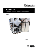
6.4. FILTER PRESSURE DROP
Pleated_Filter_PD_AUG17 14x20x2 MERV 8 (IOM)
0.0
0.1
0.2
0.3
0.4
200 300 400 500 600
Clean-filter Pressure Drop (in.w.g.)
Unit Airflow (CFM)
Initial Pressure Drop of MERV 8 Filters
supplied with this unit
FIGURE 6.4.1 INITIAL PRESSURE DROP OF MERV 8 FILTERS, SUPPLIED WITH THIS UNIT
FIGURE 6.4.2 INITIAL PRESSURE DROP OF MERV 13 FILTERS, AVAILABLE AS AN ACCESSORY
Pleated_Filter_PD_AUG17 14x20x2 MERV 13 (IOM)
0.0
0.1
0.2
0.3
0.4
200 300 400 500 600
Clean-filter Pressure Drop (in.w.g.)
Unit Airflow (CFM)
Initial Pressure Drop of MERV 13 Filters
(available option)
6.3 UNIT START-UP
6.3.1 Fixed-Speed Units
Most fixed-speed units do not have any external controlling signals and only require turning on
the disconnect switch, located on the E-Box. When the disconnect switch is turned ON, power
is suppled to the motor contactors, causing the fans to run.
Some fixed-speed units are wired to receive an actuating signal from an external source.
If there is an external actuating signal source, verify the type of signal and that it is wired
according to the low-voltage wiring diagrams found in Section 5.5 of this manual. Turn on the
disconnect switch and then turn ON the actuating device. Power is then applied to the motor
contactors and the fans will begin running.
NOTE: Make sure
clean filters are
installed before
balancing airflow. Dirty
or clogged filters reduce
airflow through the unit.

1.800.627.449920
EV-Series Outdoor
ERV
MAINTENANCE
7.0 MAINTENANCE
Danger of injury from
un-guarded blower in unit.
Disconnect power to unit
before opening door. Dan-
ger of injury if unit starts
unexpectedly. Switch
power off at service dis-
connect. Lock-out/tag-out
the disconnect.
WARNING
RenewAire ERVs are built to operate with minimal maintenance. After unit commissioning, the
primary areas of attention are the air filters and annual vacuuming of the enthalpic cores.
7.3 MAINTENANCE SCHEDULE
Experience on the part of the service person is the most important issue in establishing a
maintenance schedule. There will be times of the year when frequent inspection of the filters
will be required, such as spring and summer when there may be pollen, dust, dirt or debris from
budding trees and bushes that can clog the filters. Also see Section 7.7 Maintenance Records in
this manual.
NOTE: Always
replace securing
screw when rein-
stalling door.
6.5 NORMAL OPERATION
A wide variety of control schemes may be selected by the engineer, installer, or owner to
meet the ventilation needs of the facility. These may include timer clocks, occupancy sensors,
dehumidistats (for cool-weather operation), carbon dioxide sensors, and others. DDC systems
may also control the unit. Most control schemes will operate the unit only when needed.
Continuous operation is acceptable in virtually all conditions. Unit will not be damaged
by continuous operation as long as air flow occurs. Blower motors may overheat if filters
become completely blocked due to lack of maintenance. Motors are thermally protected. With
continuous operation, some external frosting may occur in very cold weather (see Section 6.6).
6.6 EXTREME COLD OPERATION
EV450RT units are capable of operating without internal frosting at temperatures down to
-10°F, with indoor humidity below 40%. The units can operate under more severe conditions
occasionally with little or no impact on their performance. At lower humidities, they can operate
at still lower outside temperatures without freezing the enthalpic cores.
Some condensation or even frost may form on the outside of the unit or drip off the cabinet
during very cold conditions, especially if the unit runs continuously. Exterior condensation
during extreme cold conditions can be reduced or prevented by periodically cycling the unit OFF
for several minutes to allow the cabinet to warm up.
7.1 MAINTENANCE 24 HRS. AFTER START-UP
24 hours after unit start-up:
u In new installations, check the air filters since they will often collect dust, dirt and debris at
time of start-up.
7.2 MAINTENANCE 30 DAYS AFTER START-UP
After 30 days of operation:
u Tighten all electrical connections.
u Check the air filters as part of the normal monthly maintenance.
RISK OF INJURY OR DAMAGE.
Motor may have a manual reset thermal protector. Disconnect power before servicing or
resetting motor thermal protector. Use caution, motor may be hot. Allow the motor to cool
before resetting the thermal protector.
If the motor thermal protector tripped, correct the issue that caused the motor to overheat
(e.g. over motor rated amperage or locked rotor).
If the motor has a manual reset thermal protector, the red thermal protector reset button is
located on the motor body, on or near the lead end of the motor. If the button does not reset,
the motor may still be too hot. Allow the motor to fully cool to reset the thermal protector, you
should feel or hear a click when the thermal protector resets while pushing the reset button.
WARNING
/