Pentair Acu-Trol Chemical Controller AK110 Owner's manual
- Type
- Owner's manual

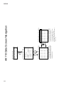
ACU-TROL® CHEMICAL CONTROLLER
FOR POOL AND SPA
MODEL AK110
INSTALLATION AND
USER’S GUIDE
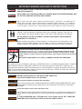
IMPORTANT SAFETY INSTRUCTIONS
READ AND FOLLOW ALL INSTRUCTIONS
SAVE THESE INSTRUCTIONS
Certied to
NS F/ ANSI Standa rd 50

2
If you have questions about ordering Pentair Aquatic Systems replacement parts, and pool products, please contact:
CUSTOMER SERVICE / TECHNICAL SUPPORT
Customer Service and Technical Support, USA
(8 A.M. to 4:30 P.M. — Eastern/Pacific Times)
Phone: (800) 831-7133
Fax: (800) 284-4151
Web site
Visit www.pentairpool.com or www.staritepool.com
Sanford, North Carolina (8 A.M. to 4:30 P.M. ET)
Phone: (919) 566-8000
Fax: (919) 566-8920
Moorpark, California (8 A.M. to 5 P.M. PT)
Phone: (805) 553-5000 (Ext. 5591)
Fax: (805) 553-5515

3
CONTENTS
SECTION 1 INFORMATION
IMPORTANT WARNING AND SAFETY INSTRUCTIONS .......................................................... 56
CONTROLLER OVERVIEW. . . . . . . . . . . . . . . . . . . . . . . . . . . . . . . . . . . . . . . . . . . . . . . . . . . . . . . . . . . . . . . . . . . . . . . . . . . . . . . . . . . . . . 7
SECTION 2 INSTALLATION
INSTALLATION PREPARATION .................................................................................8
INSTALLATION SUMMARY. . . . . . . . . . . . . . . . . . . . . . . . . . . . . . . . . . . . . . . . . . . . . . . . . . . . . . . . . . . . . . . . . . . . . . . . . . . . . . . . . . . 8
MOUNTING INSTRUCTIONS . . . . . . . . . . . . . . . . . . . . . . . . . . . . . . . . . . . . . . . . . . . . . . . . . . . . . . . . . . . . . . . . . . . . . . . . . . . . . . . . . 9
ELECTRICAL SPECIFICATIONS ................................................................................. 10
INPUT VOLTAGE SELECTION. . . . . . . . . . . . . . . . . . . . . . . . . . . . . . . . . . . . . . . . . . . . . . . . . . . . . . . . . . . . . . . . . . . . . . . . . . . . . . . . . 10
CONNECTING POWER. . . . . . . . . . . . . . . . . . . . . . . . . . . . . . . . . . . . . . . . . . . . . . . . . . . . . . . . . . . . . . . . . . . . . . . . . . . . . . . . . . . . . . . . . 10
ELECTRICAL LOADS . . . . . . . . . . . . . . . . . . . . . . . . . . . . . . . . . . . . . . . . . . . . . . . . . . . . . . . . . . . . . . . . . . . . . . . . . . . . . . . . . . . . . . . . . 11
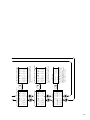
RELAY BOARD. . . . . . . . . . . . . . . . . . . . . . . . . . . . . . . . . . . . . . . . . . . . . . . . . . . . . . . . . . . . . . . . . . . . . . . . . . . . . . . . . . . . . . . . . . . . . . . 12
CHEMICAL FEED PUMP LOCATION ..........................................................................13
HEATER INSTALLATION .....................................................................................13
PLUMBING INSTALLATION ....................................................................................14
SECTION 3 HARDWARE
MODULES .................................................................................................... 16
SENSOR MODULES. . . . . . . . . . . . . . . . . . . . . . . . . . . . . . . . . . . . . . . . . . . . . . . . . . . . . . . . . . . . . . . . . . . . . . . . . . . . . . . . . . . . . . . . . . 16
COMMUNICATION MODULES ...............................................................................16
RELAY MODULES. . . . . . . . . . . . . . . . . . . . . . . . . . . . . . . . . . . . . . . . . . . . . . . . . . . . . . . . . . . . . . . . . . . . . . . . . . . . . . . . . . . . . . . . . . . . 16
SECTION 4 AK1200 FLOW CELL
AK1200 FLOW CELL ...........................................................................................18
FLOW CELL ASSEMBLY ......................................................................................19
FLOW CELL MOUNTING . . . . . . . . . . . . . . . . . . . . . . . . . . . . . . . . . . . . . . . . . . . . . . . . . . . . . . . . . . . . . . . . . . . . . . . . . . . . . . . . . . . . . 19
INLET AND EXIT LINES ...................................................................................... 19
SENSORS ................................................................................................... 19
SECTION 5 SENSORS
pH AND ORP SENSORS ........................................................................................ 21
CALCULATED PPM ............................................................................................22
AKCOLOR PPM ................................................................................................ 22
TEMPERATURE SENSOR .......................................................................................22
FLOW SENSORS . . . . . . . . . . . . . . . . . . . . . . . . . . . . . . . . . . . . . . . . . . . . . . . . . . . . . . . . . . . . . . . . . . . . . . . . . . . . . . . . . . . . . . . . . . . . . . . 22
SENSOR CARE. . . . . . . . . . . . . . . . . . . . . . . . . . . . . . . . . . . . . . . . . . . . . . . . . . . . . . . . . . . . . . . . . . . . . . . . . . . . . . . . . . . . . . . . . . . . . . . . . 23
FINISHING AND TESTING THE INSTALLATION . . . . . . . . . . . . . . . . . . . . . . . . . . . . . . . . . . . . . . . . . . . . . . . . . . . . . . . . . . . . . . . . . . 23
SECTION 6 OPERATIONS
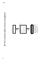
CONTROLLER WINDOW NAVIGATION ......................................................................... 24
SELECTING ITEMS IN THE WINDOWS ........................................................................25
MAKING CHANGES. . . . . . . . . . . . . . . . . . . . . . . . . . . . . . . . . . . . . . . . . . . . . . . . . . . . . . . . . . . . . . . . . . . . . . . . . . . . . . . . . . . . . . . . . . 25
START UP ..................................................................................................... 26
INITIALIZING THE CONTROLLER . . . . . . . . . . . . . . . . . . . . . . . . . . . . . . . . . . . . . . . . . . . . . . . . . . . . . . . . . . . . . . . . . . . . . . . . . . . . . . . 26
POWER UP SCREEN ...........................................................................................26
DISPLAY SCREEN. . . . . . . . . . . . . . . . . . . . . . . . . . . . . . . . . . . . . . . . . . . . . . . . . . . . . . . . . . . . . . . . . . . . . . . . . . . . . . . . . . . . . . . . . . . . . . 27
THE DISPLAY SCREEN ......................................................................................... 27
CALIBRATING TEMPERATURE ................................................................................ 27
CALIBRATING pH ............................................................................................28
CALIBRATING ORP ..........................................................................................28
CALIBRATING CALCULATED PPM ............................................................................29
MANUAL RELAY CONTROL . . . . . . . . . . . . . . . . . . . . . . . . . . . . . . . . . . . . . . . . . . . . . . . . . . . . . . . . . . . . . . . . . . . . . . . . . . . . . . . . . . 29
RELAY TIME DISPLAY ........................................................................................ 30
SET UP FLOW ...............................................................................................30
CONFIGURATION MENU ....................................................................................31
NAME. . . . . . . . . . . . . . . . . . . . . . . . . . . . . . . . . . . . . . . . . . . . . . . . . . . . . . . . . . . . . . . . . . . . . . . . . . . . . . . . . . . . . . . . . . . . . . . . . . . . . . . 32
SYSTEM. . . . . . . . . . . . . . . . . . . . . . . . . . . . . . . . . . . . . . . . . . . . . . . . . . . . . . . . . . . . . . . . . . . . . . . . . . . . . . . . . . . . . . . . . . . . . . . . . . . . . 32

4
PROGRAMMING ............................................................................................ 33
SERVICE .................................................................................................... 35
DATA ....................................................................................................... 35
COMMUNICATIONS . . . . . . . . . . . . . . . . . . . . . . . . . . . . . . . . . . . . . . . . . . . . . . . . . . . . . . . . . . . . . . . . . . . . . . . . . . . . . . . . . . . . . . . . . 36
PAGER SETUP SCREENS .....................................................................................36
EMAIL SETUP ............................................................................................... 37
SECURITY . . . . . . . . . . . . . . . . . . . . . . . . . . . . . . . . . . . . . . . . . . . . . . . . . . . . . . . . . . . . . . . . . . . . . . . . . . . . . . . . . . . . . . . . . . . . . . . . . . . 37
WIZARDS ................................................................................................... 38
SECTION 7 TROUBLESHOOTING
COMMON PROBLEMS . . . . . . . . . . . . . . . . . . . . . . . . . . . . . . . . . . . . . . . . . . . . . . . . . . . . . . . . . . . . . . . . . . . . . . . . . . . . . . . . . . . . . . . . . 39
REAL TIME CLOCK ............................................................................................39
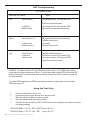
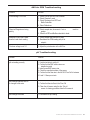
ORP TROUBLESHOOTING .....................................................................................40
USING THE TEST STRIP ........................................................................................ 40
AKCOLOR PPM TROUBLESHOOTING. . . . . . . . . . . . . . . . . . . . . . . . . . . . . . . . . . . . . . . . . . . . . . . . . . . . . . . . . . . . . . . . . . . . . . . . . . . 41
pH TROUBLESHOOTING. . . . . . . . . . . . . . . . . . . . . . . . . . . . . . . . . . . . . . . . . . . . . . . . . . . . . . . . . . . . . . . . . . . . . . . . . . . . . . . . . . . . . . . 41
SECTION 8 APPENDIXES
UTILITY PASSWORDS 90009020 .............................................................................. 42
SETUP DIGITAL FLOW ........................................................................................ 42
PROPORTIONAL FEED. . . . . . . . . . . . . . . . . . . . . . . . . . . . . . . . . . . . . . . . . . . . . . . . . . . . . . . . . . . . . . . . . . . . . . . . . . . . . . . . . . . . . . . . . 42
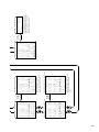
SECTION 9 WIRING DIAGRAMS
RELAY WIRING DIAGRAMS ....................................................................................43
SENSOR WIRING DIAGRAMS. . . . . . . . . . . . . . . . . . . . . . . . . . . . . . . . . . . . . . . . . . . . . . . . . . . . . . . . . . . . . . . . . . . . . . . . . . . . . . . . . . . 44
SECTION 10 MENUS
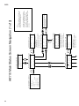
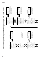
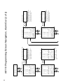
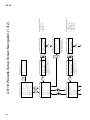
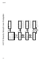
SCREEN NAVIGATION KEYS ............................................................................................45
MAIN STATUS SCREEN NAVIGATIONS. . . . . . . . . . . . . . . . . . . . . . . . . . . . . . . . . . . . . . . . . . . . . . . . . . . . . . . . . . . . . . . . . . . . . . . . . . 46
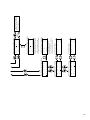
RELAY AND ALARM TIMER SCREEN NAVIGATION ..............................................................50
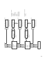
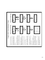
CONFIGURATION MENU SCREEN NAVIGATION ................................................................ 52
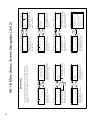
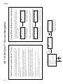
CONTROLLER NAME SCREEN NAVIGATION .................................................................... 54
SYSTEM SETUP SCREEN NAVIGATION. . . . . . . . . . . . . . . . . . . . . . . . . . . . . . . . . . . . . . . . . . . . . . . . . . . . . . . . . . . . . . . . . . . . . . . . . . 56
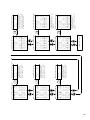
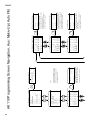
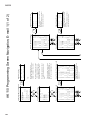
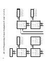
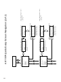
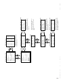
PROGRAMMING SCREEN NAVIGATION , pH MIX TIME . . . . . . . . . . . . . . . . . . . . . . . . . . . . . . . . . . . . . . . . . . . . . . . . . . . . . . . . . . 58
PROGRAMMING SCREEN NAVIGATION, pH CYCLE TIME ........................................................ 60
PROGRAMMING SCREEN NAVIGATION, ORP MIX TIME . . . . . . . . . . . . . . . . . . . . . . . . . . . . . . . . . . . . . . . . . . . . . . . . . . . . . . . . . 62
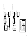
PROGRAMMING SCREEN NAVIGATION, ORP CYCLE TIME ...................................................... 66
PROGRAMMING SCREEN NAVIGATION, ORP CAL HYPO ........................................................ 70
PROGRAMMING SCREEN NAVIGATION, PPM CYCLE TIME ...................................................... 74
PROGRAMMING SCREEN NAVIGATION, PMM MIX TIME ........................................................ 78
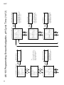
PROGRAMMING SCREEN NAVIGATION, PROBE CLEAN . . . . . . . . . . . . . . . . . . . . . . . . . . . . . . . . . . . . . . . . . . . . . . . . . . . . . . . . . 82
PROGRAMMING SCREEN NAVIGATION, HEATER ............................................................... 84
PROGRAMMING SCREEN NAVIGATION, ALARM OUT. . . . . . . . . . . . . . . . . . . . . . . . . . . . . . . . . . . . . . . . . . . . . . . . . . . . . . . . . . . 96
PROGRAMMING SCREEN NAVIGATION, AUX. MAKEUP AUTOFILL ........................................... 90
PROGRAMMING SCREEN NAVIGATION, DAILY EVENT .......................................................... 92
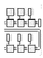
PROGRAMMING SCREEN NAVIGATION, WEEKLY EVENT ........................................................96
PROGRAMMING SCREEN NAVIGATION, FRONT PANEL ALARM .................................................96
PROGRAMMING SCREEN NAVIGATION, PAGER. . . . . . . . . . . . . . . . . . . . . . . . . . . . . . . . . . . . . . . . . . . . . . . . . . . . . . . . . . . . . . . . . 100
PROGRAMMING SCREEN NAVIGATION, EMAIL ................................................................ 104
WIZARDS SETUP SCREEN NAVIGATION ........................................................................ 108
DATA SCREEN NAVIGATION ................................................................................... 112
COMMUNICATIONS SCREEN DIALUP ......................................................................... 114
COMMUNICATIONS SCREEN INTERNET MODEMS. . . . . . . . . . . . . . . . . . . . . . . . . . . . . . . . . . . . . . . . . . . . . . . . . . . . . . . . . . . . . . 118
SECURITY SETUP SCREEN NAVIGATION ........................................................................ 124
AKCOLOR SCREEN NAVIGATION .............................................................................. 126
SERVICE SCREEN NAVIGATION ................................................................................128
CONTENTS (Continued)
AK110 CHEMICAL CONTROLLER ILLUSTRATED PARTS LIST .............................................................130

5
ACU-TROL® AK110 Chemical Controller Installation and User's Guide
Most states and local codes regulate the construction, installation, and operation of
public pools and spas, and the construction of residential pools and spas. It is important
to comply with these codes, many of which directly regulate the installation and use
of this product. Consult your local building and health codes for more information.
SERIOUS BODILY INJURY OR DEATH CAN RESULT IF THIS PRODUCT IS NOT INSTALLED
AND USED CORRECTLY.
INSTALLERS, POOL OPERATORS AND POOL OWNERS MUST READ THESE WARNINGS AND
ALL INSTRUCTIONS BEFORE USING THIS PRODUCT.
IMPORTANT NOTICE - Attention Installer: This Installation and User’s Guide
(“Guide”) contains important information about the installation, operation and safe use
of this product. This Guide should be given to the owner and/or operator of this product.
DO NOT INSTALL THE AK110 CHEMICAL CONTROLLER WHERE IT CAN BE READILY
ACCESSIBLE TO THE PUBLIC.
Before installing this product, read and follow all warning notices and instructions in this
Guide. Failure to follow warnings and instructions can result in severe injury, death, or
property damage. Call (800) 831-7133 for additional free copies of these instructions.
BEFORE WORKING ON THE AK110 CHEMICAL CONTROLLER: Always disconnect power to the
IntelliChem controller at the circuit breaker before servicing. Failure to do so could
result in death or serious injury to service person, pool users or others due to electric
shock.
RISK OF ELECTRICAL SHOCK OR ELECTROCUTION:
This product must be installed by a licensed or certified electrician or a qualified pool professional in accordance
with the National Electrical Code (NEC), NFPA 70 or the Canadian Electrical Code (CEC), CSA C22.2. All
applicable local installation codes and ordinances must also be adhered to. Improper installation will create an
electrical hazard which could result in death or serious injury to pool users, installers or others due to electrical
shock, and may also cause damage to property.
Do not permit children to operate this equipment.
When mixing acid with water, ALWAYS ADD ACID TO WATER. NEVER ADD WATER TO ACID.
When adding any chemical to the pool/spa, be sure to follow the manufacturer’s instructions
thoroughly.
DO NOT MIX SODIUM HYPOCHLORITE AND MURATIC ACID
Risk of electrical shock. Connect AK110 Chemical Controller to a ground-fault interrupter-circuit
(GFCI). Contact a qualified electrician if you cannot verify that the receptacle is protected by a
GFCI.
BE SURE TO DISCONNECT ALL SUPPLY CONNECTIONS BEFORE SERVICING.
BEFORE USING YOUR POOL, SPA OR HOT TUB, CHECK THE
pH AND SANITIZER LEVELS OF THE WATER.
IF “CLEAR OVERFEED LIMIT” SETTING IS SET TO 24 HOURS, DO NOT SET “FEED TIME”
GREATER THAN 20 HOURS AS THIS WILL VOID NSF CERTIFICATION.
IMPORTANT WARNING AND SAFETY INSTRUCTIONS

6ACU-TROL® AK110 Chemical Controller Installation and User's Guide
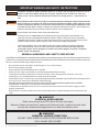
WARNING
CHEMICAL BURN HAZARD
Make sure pumps are OFF before drilling into pipes.
Securely fasten all electrical, water and chemical lines. Locate chemical feed
pumps and chemical storage tanks in a safe and secure area.
PLEASE READ THIS USER MANUAL completely before installing or operating the equipment . The Controller Pool and Spa Chemical Con-
troller is a Class 1 product for protection against electric shock and a Type 1 product with regards to disconnection of the control circuits.
Be sure to observe the following safety precautions:
• Donotpermitanyoneuntrainedorundertheageof18tousethisproduct.
• Unitmustbeproperlygrounded.
• Frontpanelmustbeclosedbeforepowerisapplied.
• AlwaysturnOFFmaincircuitbreakertounitandallequipmentbeforeservicing.
• Touchingthecontroller’sinternalpartscouldresultininjuryandordamagetothecontroller.Incaseofa
malfunction, only a qualied technician should repair the controller.
• RiskofElectricShock.Connectonlytoagroundingtypereceptacleprotectedbyaground-faultcircuitinterrupter(GFCI).
• Donotburycord.Routecordtoeliminateexternaldamage.
• Becarefulnottodamageanyoftheinsulationonwiresorthepowercord.Shouldthecordbedamaged,returnittoyourdealerfor
a replacement. Continued use could result in re or electric shock.
• Toreducetheriskofelectricshock,donotuseanextensioncordtoconnectunittoelectricsupply,providea
properly located GFCI.
• Neverremoveorinstallanycablesonthecircuitcardswhenpowerisapplied,damagetothecomponentsmay
occur.
GENERAL WARNINGS AND SAFETY PRECATIONS
!
WARNING
CHEMICAL HAZARD CONDITION
DO NOT TURN CHEMICAL FEED PUMPS ON WHEN BOTH FLOW
CELL VALVES ARE CLOSED.
!
WARNING CHEMICAL BURN HAZARD: Make sure all pumps are switched off at the main circuit
breakers at the house before drilling into any pipes. Securely fasten all electrical, water and
chemical lines. Locate chemical feed pumps and chemical storage tanks in a safe and secure
area.
Strictly follow the acid manufacturers safety and handling protocols including hand, body and eye protection
when transferring or handling acid. Safety precautions should be used when handling Muriatic acid to
control pH water levels. Muriatic acid can cause serious body injury and damage pool equipment. Extra
care must be taken when installing, maintaining and operating acid pump feed systems. Acid is dangerous to
handle and should be properly contained, transported, poured, stored, and dispensed.
Check the pH and sanitizer levels of the water before use.
Periodically use an independent pH and Chlorine test kit to verify that pH and chlorine is at a
safe level. If the pH and Oxidation Reduction Potential (ORP) or Flow Cell sensors are broken,
depleted or dirty with oils, lotions, or other contaminants, they can report inaccurate results to the
system causing incorrect water chemistry, which could harm people or equipment.
Check the IntelliChem main status display each day to ensure there are no Alarm messages.
See “Troubleshooting” section for more information.installing, maintaining and operating acid
pump feed systems. Acid is dangerous to handle and should be properly contained, transported,
poured, stored, and dispensed.
IMPORTANT WARNING AND SAFETY INSTRUCTIONS

7
ACU-TROL® AK110 Chemical Controller Installation and User's Guide
The AK110PS Pool and Spa Chemical Controller ("Controller") is a microprocessor based modular automation system
capable of continuous local or remote monitoring and control of water chemistry for pool and spa applications. The
Controller will maintain the pH and sanitizer levels of your water system automatically. Customized applications are
possible with the addition of optional expansion modules.
MODULAR: The Controller is designed to grow with the needs of the customer. There are optional modules that can
be installed as the need arises without having to remove the Controller from the wall.
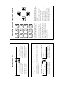
INTERFACE: The Controller uses a built-in keypad with 16 buttons, and an easy to read 80 character liquid crystal
display. The display’s internal back-light provides viewing in low light conditions. The back-light illumination time can be
adjusted to suit the operator.
MENUS: The Controller features easy to use display menus for on screen navigation.
MEMORY: In case of power loss, all set-points and programming are retained in nonvolatile memory. These values will
be protected for a minimum ten (10) years without having power applied.
DATA RECORDING: The Controller has the ability to record data at 2 hour time intervals. Over 1 month of data can be
recorded before lling up the memory. When the memory is full the new data will overwrite the oldest data.
RELAYS: The Controller can control up to three (3) relays. There are various types of relay congurations available to
different types of load requirements.
DISPLAYS: The Controller can display measurements, relay ON/OFF states, length of time that relays have been on
and the alarm status.
SENSORS: The Controller can measure readings and control based on inputs from the following sensors: temperature,
digital ow, pH, ORP, and AKColor PPM.
VOLTAGE: The Controller includes a switch to select the input voltage of 110 or 220 VAC (single or dual phase).
HEALTH: The Controller can be congured to maintain the bacteriological and physiological requirements of state and
local health departments. In addition, the Controller has the capability to be congured such that equipment can be
protected from the effects of improper water balance.
REMOTE MONITORING: The Controller can be easily congured for remote, full duplex communication using an
internal 56K modem and a phone line, or a wireless modem and an internet connection. This feature allows a user
remote access to Controller operations using an MS Windows Based PC and the Acu-Com Software. The Acu-Com
Software is a full featured software package that allows the operator to download recorded data, monitor system
inputs in real time and provides a graphing option that allows for detailed analysis of water system parameters and
performance. In addition, AcuManage II, an online database management system will display data from any internet
enabled Controller.
REMOTE PAGING: With the optional modem installed, the Controller can be programmed to dial out to electronic
paging systems for notifying operators of an alarm condition.
REMOTE EMAILING: With the optional wireless modem installed, the Controller can be programmed to send an email
notifying operators of an alarm condition.
SECURITY: The Controller provides two level security protection based on passwords for both local and remote
interaction.
AK110 Pool and Spa Chemical Controller Overview

8ACU-TROL® AK110 Chemical Controller Installation and User's Guide
SECTION 2
INSTALLATION
Installation Preparation
Installation Summary
Inspection: Upon receiving the Controller check the carton carefully. Report any shipping damage to shipping
company. Examine the enclosed shipping list and verify that all items are present. Contact Customer Support
(800) 831.7133 if any items are missing or have been damaged. Use care when unpacking equipment to avoid
damage or loss of small parts. Verify that the fuses are the correct values and that the voltage select switch is in
the proper position.
The following steps are required to install the Controller:
1. Identify new and existing equipment to be connected.
2. Decide if the sensors will be in-line, in a separate by-pass line, or if the AK1200 ow cell will be used.
Caution: If the AK1200 ow cell is used, the input water maximum pressure is 25 PSI.
3. Determine the supply voltage, 110 VAC or 220 VAC, and set the supply voltage switch as necessary.
4. Determine if the control to the equipment uses the same voltage as the supply voltage.
All controlled equipment must be compatible.
5. Determine the water-tap points for the ow cell bypass inlet and outlet.
6. Mount the Controller away from direct sunlight and on a at vertical surface.
7. Connect the supply voltage with main breaker off. (Must be a separate dedicated circuit GFCI).
8. If using an AK1200 ow cell install the bypass now.
9. Connect the sensors.
10. Test the plumbing for leaks.
11. Turn on the Controller for the rst time.
12. Test the equipment, using the Controller manual relay mode.
13. Calibrate the probes, then re-calibrate as the probes acclimate to the system.
Acclimation can take as little as two hours or as long as 24 hours.
14. Program the Controller.
15. Call or visit the controller over the next few days to insure the system is balanced and in control.
Fine-tune the setup if necessary.

9
ACU-TROL® AK110 Chemical Controller Installation and User's Guide
WARNING
Keep the Controller out of direct sunlight, inside a room if possible.
Direct sunlight on the Controller will result in inaccurate readings.
A shade screen should be used for outdoor installations.
Mounting Instructions
Select a location for mounting the Controller, meeting the following recommendations:
1. Mount at least ten (10) feet from open water.
2. Mount close enough for the supplied power cord to reach the supply voltage. The Controller will not operate
properly without a solid earth ground connection.
3. Supply power must be routed to the Controller in accordance with the applicable codes in the area; the
supplied power cord is not code in some areas.
4. The installation surface must be solid and vertical. Do not mount the Controller in a horizontal position.
WARNING
Proper and safe operation requires an earth ground connection.
5. Maintain adequate clearance for opening the front panel enclosure.
6. The environment should be free of chemical fumes and excessive heat.
The maximum room temperature is should not exceed 110 ºF.
7. Mount as far as possible from sources of electrical interference.
8. Install the four mounting feet as desired to the Controller back and prepare the hole to the mounting
surface as desired.
9. Hold the Controller against the mounting surface with a closed lid and mark the location of the mounting
bracket located on the top of the Controller next to the wall. Prepare holes as necessary and secure
Controller using hardware provided.
10. Mount on a at surface. Controller box will distort if mounted on an uneven surface.
11. Pre-install screws with ¼ left out on bottom so that the Controller can slide into them. Install the remaining
side screws and tighten.
!
!

10 ACU-TROL® AK110 Chemical Controller Installation and User's Guide
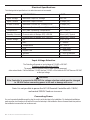
Input Voltage Maximum Input AC Voltage 250 VAC
Input Current Maximum Input Current 5 Amps (AC)
Output Current Maximum Current for 3 Relays 110V 5 Amps (AC)
Maximum Combined Current 3 Relays 24V Dry 1 Amp
Temperature Min./Max. Operating Temperature 30° - 110° F
Standby Current Current with all Relays OFF, LED ON 50mA (AC) Typical
Current with all Relays OFF, LED OFF 30mA (AC) Typical
Sensor Range pH 4.22 - 9.78
ORP 0 - 999mV
Temperature 32 - 212° F
PPM 0 - 9.99 PPM
Digital Flow 0 - 9999 GPM
Volume 0 - 65,535 Gallons
Flow Open or Closed
Electrical Specications
The following electrical specications in the table below must not be exceeded.
Input Voltage Selection
The Controller will operate on input voltages of 110 VAC or 220 VAC.
The factory jumper setting is for 110 VAC.
The supply power is commonly used to power the feed pumps and
other external loads. If all the loads are 110 VAC then use 110 VAC or if the loads are 220 VAC then use 220 VAC
as the input voltage.
Note: It is not possible to power the AK110 Chemical Controller with 110 VAC,
and control 220 VAC loads or vise versa.
Connecting Power
For cord connected installations wait to plug the cord in as the last step in the installation. For hard-wired installations
make sure the circuit breaker is off and turn it on as the last step in the installation. Have a licensed electrician perform
the installation to ensure the local codes are met.
WARNING
If the Controller is connected to 220 VAC the voltage selection switch must be changed
to 220 VAC before connecting power to the unit or damage will occur.
!
ITEM DESCRIPTION LIMIT

11
ACU-TROL® AK110 Chemical Controller Installation and User's Guide
Electrical Loads
The Controller with revision F and greater relay board has the capability of utilizing up to three (3) modular relay boards
that can be purchased in a number of congurations. The Controller is shipped from the factory with three (3) 110 VAC
Normally Open modules installed (Part# 724000050). Listed below are the different types of relay modules that can
be purchased and their function. The correct ones must be ordered based on the load requirements. Check with your
distributor for the proper relay modules for your application.
The wiring on each board may be different depending on the model that you purchase. Look on the board, check with
your distributor or call Pentair Customer Support at 800-831-7133 with any questions.
WARNING
Do not change relay modules when power is applied.
This type of damage is not covered in the warranty.
Do not connect any load not rated for the supply voltage to any of these relays.
TOTAL COMBINED LOADS MUST BE LESS THAN FIVE (5) AMPS
FOR ALL THREE RELAYS.
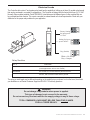
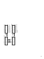
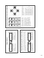
Factory Setting
for input power
115 VAC
White = No Jumper
Grey = Jumper
Setting for input
power 24VAC
Dry (Switch)
Part # FUNCTION
724000050 For control of 110 VAC Normally Open Circuits
(most applications will use this model).
724000060 For control of 110 VAC Normally Closed Circuits.
724000440 For control of 110 VAC Single Pole, Double Throw
Circuits, with common white and no ground.
Relay Modules
!

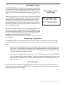
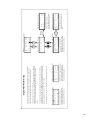
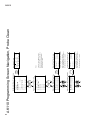
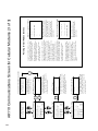
12 ACU-TROL® AK110 Chemical Controller Installation and User's Guide
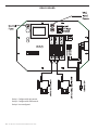
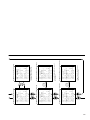
Relay 1: Congured for pH control.
Relay 2: Congured for ORP control.
Relay 3: User congured.
115
RELAY BOARD

13
ACU-TROL® AK110 Chemical Controller Installation and User's Guide
Chemical Feed Pump Location
If unit has not been previously installed, follow the instructions included with the chemical feed pump. Some loads
include power cords already connected to the load and are ready to plug in. If “pigtails” have been ordered with the
Controller simply plug the power cord into the appropriate "pigtail". If "pigtails" are not installed the power cord from the
pump will need to be modied. The list below provides installation recommendations:
1. Mount at least 10 feet from open water.
2. Install the pump below the level of the Controller and away from any other equipment or systems.
This is to reduce any damage to other equipment should the pump leak.
3. Install close enough to the Controller for the feed pump power cords to reach.
4. If "pigtails" are included simply plug in the pumps to the appropriate "pigtail". If pigtails are not installed,
cut the electric plugs from the feed pumps and strip and ferrule the ends.
5. Route the power cords to the Controller through the lower ttings and attach to the appropriate relay
terminals on the relay circuit board. If the wire ends were striped and not ferruled make sure that no frays
of wire are out of the connector as this may lead to a short.
6. Conduit or external plugs can also be used (according to the codes in the local area).
7. When installing metal conduit into the Controller, a ground LUG should be used to connect the conduit to
the relay board ground.
Heater Installation
The Controller third relay can control a heater, turning it on and off based on the temperature settings you have
programmed in to the Controller. The heater control portion of the Controller can be used to maintain a constant
temperature or maintain a temperature during operating hours. Even though the Controller is a very accurate and
reliable device, for safety, always use the over-temp device on your heater to prevent overheating.
1. Always install any heater according to the manufacturer's instructions.
2. Mount the Controller at least 10 feet from open water.
3. Install close enough to the Controller for the wiring connections to reach.
4. DO NOT attempt to power the heater with the Controller controller.
5. A heater unit must always be independently powered, either through a separate cord, or through an
external relay like the Acu-Trol HAR1 relay module. (Part# 735000060)
6. Always use the over-temp device on the heater to prevent overheating.

14 ACU-TROL® AK110 Chemical Controller Installation and User's Guide
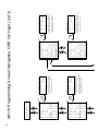
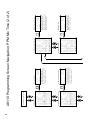
Follow the instructions that came with the AK1200 ow cell. This section gives the basic principles to be applied for any
specic installation, which are listed as follows:
1. Turn OFF all equipment including the ltration system.
2. Determine a suitable location for the ow cell. Which should be located where water spillage will not
damage surroundings.
3. Securely mount the ow cell.
4. Install the supply and return lines for each ow cell. Drill and tap ¼” holes for the ½” exible tubing or hard
plumb the ow cell.
A. Locate where the water will be supplied from and returned for each ow cell. The most common
location for the water inlet to the ow cell is after the main lter and the outlet after the heater.
B. If there is no suitable location the cell inlet can be after the main pump and the outlet before the main
pump. This method may cause a suction in the ow cell and damage to the sensors. If any chemicals
are injected into the cell they may cause temporary invalid readings.
5. Locate the chemical injection points.
6. Prepare and install the chemical injector ttings.
7. Install the chemical storage containers.
8. Install the sensors.
9. Turn ON the main circulation pump.
10. Check for leaks and verify the ow sensor indicates ow.
Plumbing Installation
WARNING
Be sure to have a licensed plumber perform all plumbing; this is important, as they will
be familiar with all of the codes in the local area.
!

15
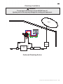
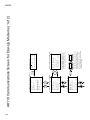
ACU-TROL® AK110 Chemical Controller Installation and User's Guide
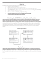
Return
Supply
Water
Sample
Test
Plumbing Installation
WARNING
Do not inject acid directly in to the AK1200 ow cell.
Injecting acid in this way may damage the existing pool equipment.
!
Preferred Plumbing Routes
Pump
Pool

16 ACU-TROL® AK110 Chemical Controller Installation and User's Guide
SECTION 3
HARDWARE
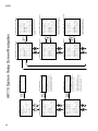
Modules are the electronic controls and components that make up the Controller.
Each module has a specic function or functions that tell the Controller what information to accept and what information
to display. The modular design of the Controller enables it to interface with many types of modules including Sensor,
Communication, and Relay modules.
Sensor modules determine the types of sensors signals the control can recieve. There are three sensor modules
currently available for the Controller.
AK111: pH, ORP, temp and heater control. Calculated PPM can also be displayed (Part# 724000010).
AK112: pH, AKColor(PPM), heater control (Part# 724000380)
AK113SC: pH AKColor(PPM) ORP, Temp (Part # 725000390)
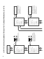
The Controller has the ability to work with several types of communication modules. The Controller can communicate
with a PC through an RS232 cable, a standard modem, or a wireless modem.
Controller Modem: High-speed modem. (Part # 725000010)
Wireless Modem: The wireless modem allows the Controller to be accessed over the internet from any PC.
Wireless modems are a perfect solution for installations without phone lines. Please note that the wireless
modem and the standard modem can not be installed in the same Controller.
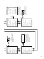
The Controller is able to automate nearly any device in your pump room. The Controller uses a relay module to turn
electricity to the device on and off. Each Controller can control up to 3 relay modules. Each relay module can control
one device. Relay modules are available in seven different models. The type of relay module used depends on the
load requirements of the device that is controlled with the relay module. To determine the load requirements, please
consult the instruction manual or the device manufacturer. Any combination of the seven models of relay modules can
be installed in the three available slots on a relay board, as long as the combination does not exceed the combined
maximum current for the relayboard. The combined maximum current for any individual relay board is 5 amps.
Modules
Sensor Modules
Communication Modules
Relay Modules

17
ACU-TROL® AK110 Chemical Controller Installation and User's Guide
The maximum relay current for the relay board is 5 amps when switching 115 VAC or 220 VAC and 1 amps when
switching 24 VAC.DRY
CONTACTS: These relays act as a dry contact switch only and have no connection to the input VAC. The relay ratings
are 5A and 250 VAC.
115 VAC Normally Closed: These relays supply the input voltage to the load when the relay is in the “OFF” mode. Note
that both VAC inputs are controlled by the relay. The relay ratings are 5A and 250 VAC.
115 VAC Normally Open: These relays supply the input voltage to the load when the relay is in the “ON” mode. Note
that both VAC inputs are controlled by the relay. The relay ratings are 5A and 250 VAC.
115 VAC SPDT: These relays are hard-wired selectable to be either NO (Normally Open) or NC (Normally Closed)
switching of the input voltage. They are always powered, and the wiring will dictate whether the power ows in the on or
off position. The relay ratings are 5A and 250 VAC. The neutral is common for both NO and NC.
24 VAC Normally Closed: These relays supply 24 VAC to the load when the relay is in the “OFF” mode. Note that both
VAC inputs are controlled by the relay. The relay ratings are 1A and 250 VAC.
24 VAC Normally Open: These relays supply 24 VAC to the load when the relay is in the “ON” mode. Note that both
VAC inputs are controlled by the relay. The relay ratings are 1A and 250 VAC.
24 VAC SPDT: These relays are hard-wired selectable to be either NO (Normally Open) or NC (Normally Closed)
switching of the 24 VAC. They are always powered, and the wiring will dictate whether the power ows in the on or off
position. The relay ratings are 1A and 250 VAC. The neutral is common for both NO and NC.

18 ACU-TROL® AK110 Chemical Controller Installation and User's Guide
SECTION 4
AK1200 FLOW CELL
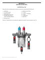
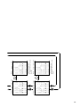
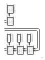
Remove ow cell from shipping carton and make sure all parts are included with AK1200 ow cell.
• 1 – AK1200 Lid • 1 – AK1200 Jar with O-Ring
• 1 – Flow switch magnet • 3 - ¼” Valves.
• 1 - Sample barb tting • 4 - ¼” NPT by ½” ex ttings.
• 1 - Filter assembly with O-Ring • 2 - ¼” plugs.
• 1 - Flow switch with O-Ring, 2’ • 1 - ¼” Close Nipple
and 10’ wire lengths available. • 1 - Teon Tape
• 2 - Mounting screws
Note that ½” exible tubing is not included and is supplied by the installer or may be ordered from Acu-Trol.
AK1200 Flow Cell

19
ACU-TROL® AK110 Chemical Controller Installation and User's Guide
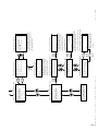
1. Wrap all four ex ttings with Teon tape.
2. Install two ex ttings into two ball valves.
3. Wrap barb tting with Teon tape. Install barb into remaining ball valve.
4. Wrap both ends of the close-nipple with Teon tape. Install into the lter assembly using (either end OK).
Hand-tighten only.
5. Install one ball valve into the lter.
6. Install the lter and remaining ball valves as shown in the gure.
7. Verify that the ow switch magnet is in the ow cell tube with the large or hat end pointing down.
NOTE: Wrap ttings only twice around with Teon tape.
Flow Cell Assembly
Select a suitable location for the ow cell meeting the following recommendations:
1. Sensors wires will connect to within ten (10) feet.
2. Do not mount in direct sunlight. SUNLIGHT WILL CAUSE INACCURATE READINGS.
3. Water leaks will cause damage! Mount where water does not leak and damage other compentents.
4. Mount ow cell vertically with provided screws.
5. Securely fasten all electrical, water and chemical lines.
6. Locate chemical feed pumps and chemical storage tanks in a safe and secure area.
7. Maximum operating pressure = 25 psi
8. Extreme pressure variances may affect readings and can cause damage to the sensors.
9. Avoid installing the outlet before the main pump as the vacuum may damage the chemical sensors.
10. Only inject chemicals on the outlet side of the AK1200 Flow Cell
11. Do not over tighten tting on ow cell top.
1. It is essential that the supply line be at a higher pressure than the discharge line so the water will ow through
the cell at a steady rate in the right direction. Installing a ball valve in the main circulation line may be required
if the pressure is too low.
2. Inlet should be installed after lter and before heater.
3. Exit should be installed after heater and as far away from any equipment as possible.
4. Drill and tap at above locations with 7/16” drill and 1/4” NPT tap. Choose a location on a tting where the
pipe enters so you are drilling through both the pipe and tting to get maximum depth of thread.
5. Install ¼” NPT by ½” ex ttings then route inlet and exit lines.
Flow Cell Mounting
Inlet and Exit Lines

20 ACU-TROL® AK110 Chemical Controller Installation and User's Guide
1. pH and ORP sensors must remain wet at all times. Install the sensors into the ow cell,
HAND-TIGHTEN ONLY and save caps for future use and ll ow cell with water.
2. Route the ow switch wires into the Controller through the strain relief and connect to the Controller.
Wire one (either one) to ground and one to the appropriate input switch.
3. Route the chemical sensors into the Controller through the strain relief and connect to the Controller.
The sensor wires are labeled and the PLUS AND MINUS POLARITY MUST BE OBSERVED.
4. Turn the main pump on and open the valves to test for leaks and the free movement of magnet.
Magnet must be all the way up in order to close the ow switch. 1/4 GPM will push the magnet all the
way up.
Sensors
CAUTION
The ow switch is a dry contact only (no current).
Use with any other brand Controller VOIDS WARRANTY.
!
WARNING:
Make sure all pumps are OFF before drilling into pipes.
Never turn chemical feed pumps ON when both
ow cell valves are closed.
!
Page is loading ...
Page is loading ...
Page is loading ...
Page is loading ...
Page is loading ...
Page is loading ...
Page is loading ...
Page is loading ...
Page is loading ...
Page is loading ...
Page is loading ...
Page is loading ...
Page is loading ...
Page is loading ...
Page is loading ...
Page is loading ...
Page is loading ...
Page is loading ...
Page is loading ...
Page is loading ...
Page is loading ...
Page is loading ...
Page is loading ...
Page is loading ...
Page is loading ...
Page is loading ...
Page is loading ...
Page is loading ...
Page is loading ...
Page is loading ...
Page is loading ...
Page is loading ...
Page is loading ...
Page is loading ...
Page is loading ...
Page is loading ...
Page is loading ...
Page is loading ...
Page is loading ...
Page is loading ...
Page is loading ...
Page is loading ...
Page is loading ...
Page is loading ...
Page is loading ...
Page is loading ...
Page is loading ...
Page is loading ...
Page is loading ...
Page is loading ...
Page is loading ...
Page is loading ...
Page is loading ...
Page is loading ...
Page is loading ...
Page is loading ...
Page is loading ...
Page is loading ...
Page is loading ...
Page is loading ...
Page is loading ...
Page is loading ...
Page is loading ...
Page is loading ...
Page is loading ...
Page is loading ...
Page is loading ...
Page is loading ...
Page is loading ...
Page is loading ...
Page is loading ...
Page is loading ...
Page is loading ...
Page is loading ...
Page is loading ...
Page is loading ...
Page is loading ...
Page is loading ...
Page is loading ...
Page is loading ...
Page is loading ...
Page is loading ...
Page is loading ...
Page is loading ...
Page is loading ...
Page is loading ...
Page is loading ...
Page is loading ...
Page is loading ...
Page is loading ...
Page is loading ...
Page is loading ...
Page is loading ...
Page is loading ...
Page is loading ...
Page is loading ...
Page is loading ...
Page is loading ...
Page is loading ...
Page is loading ...
Page is loading ...
Page is loading ...
Page is loading ...
Page is loading ...
Page is loading ...
Page is loading ...
Page is loading ...
Page is loading ...
Page is loading ...
Page is loading ...
Page is loading ...
Page is loading ...
-
 1
1
-
 2
2
-
 3
3
-
 4
4
-
 5
5
-
 6
6
-
 7
7
-
 8
8
-
 9
9
-
 10
10
-
 11
11
-
 12
12
-
 13
13
-
 14
14
-
 15
15
-
 16
16
-
 17
17
-
 18
18
-
 19
19
-
 20
20
-
 21
21
-
 22
22
-
 23
23
-
 24
24
-
 25
25
-
 26
26
-
 27
27
-
 28
28
-
 29
29
-
 30
30
-
 31
31
-
 32
32
-
 33
33
-
 34
34
-
 35
35
-
 36
36
-
 37
37
-
 38
38
-
 39
39
-
 40
40
-
 41
41
-
 42
42
-
 43
43
-
 44
44
-
 45
45
-
 46
46
-
 47
47
-
 48
48
-
 49
49
-
 50
50
-
 51
51
-
 52
52
-
 53
53
-
 54
54
-
 55
55
-
 56
56
-
 57
57
-
 58
58
-
 59
59
-
 60
60
-
 61
61
-
 62
62
-
 63
63
-
 64
64
-
 65
65
-
 66
66
-
 67
67
-
 68
68
-
 69
69
-
 70
70
-
 71
71
-
 72
72
-
 73
73
-
 74
74
-
 75
75
-
 76
76
-
 77
77
-
 78
78
-
 79
79
-
 80
80
-
 81
81
-
 82
82
-
 83
83
-
 84
84
-
 85
85
-
 86
86
-
 87
87
-
 88
88
-
 89
89
-
 90
90
-
 91
91
-
 92
92
-
 93
93
-
 94
94
-
 95
95
-
 96
96
-
 97
97
-
 98
98
-
 99
99
-
 100
100
-
 101
101
-
 102
102
-
 103
103
-
 104
104
-
 105
105
-
 106
106
-
 107
107
-
 108
108
-
 109
109
-
 110
110
-
 111
111
-
 112
112
-
 113
113
-
 114
114
-
 115
115
-
 116
116
-
 117
117
-
 118
118
-
 119
119
-
 120
120
-
 121
121
-
 122
122
-
 123
123
-
 124
124
-
 125
125
-
 126
126
-
 127
127
-
 128
128
-
 129
129
-
 130
130
-
 131
131
-
 132
132


Pentair Acu-Trol Chemical Controller AK110 Owner's manual
- Type
- Owner's manual
Ask a question and I''ll find the answer in the document
Finding information in a document is now easier with AI
Related papers
-
Pentair Acu-Trol Chemical Controller AK600 Owner's manual
-
-
-
Pentair Pool Intellicenter Control System Installation guide
-
-
Pentair Maestro User manual
Other documents
-
Pentair Pool Commercial IntelliChem Chemical Controller Owner's manual
-
-
ProMinent DCM 2 Series Installation guide
-
 Balboa Instruments Eco-matic ESC 36 Installation guide
-
-
Aquacal Pool Pilot 75003 User manual
-
Omega CDCN12 and CDCN13 Owner's manual
-
-
Hayward Aqua Plus® Operating instructions
-
 ROLA-CHEM RC554XP Operating instructions

