OVUR-type oil separator
2108 HP, 3209 HP, 4012 HP, 5014 HP, 6014 HP
Installation, Operation and Maintenance manual
en


Installation, operation and maintenance manual - OVUR-type oil separator
0012381 en 2020.08 3/7
OVUR-type oil separator
Installation, operation and maintenance manual
Design
In principle the oil separator consists of a shell with an end cover. Nozzles are welded in the shell.
On delivery the nozzles are blanked off with seal caps, which protect against moisture and dirt
during transport and storage.
Application
The oil used in the compressor for lubrication, sealing and cooling of the compressor block is
mixed with the refrigerant gas and together they are transferred to the oil separator. Oil and gas
are separated in the oil separator and the now almost oil-free gas leaves the compressor unit
through the discharge branch.
Product description
In the separator, filter elements separate the oil from the gas. Most of it is separated in the demis-
ters and drained to the bottom of the oil separators. The separated oil is returned to the compres-
sor through a special oil return system. The remaining oil in the gas is separated in the fine
separator element and returned to the compressor through the oil return. Normally, it is superflu-
ous to remove or replace the fine separator element, but at increasing oil consumption it is possi-
ble to inspect the filter or extract it through the flange.
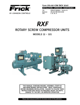
OVUR
type Part no.
Connec-
tion
DN
Bolt
Torque Nm Volume
liter
Weight
Kg
Operation Test PED
2108 HP 4241.424.PED 50 M22 200 250 27 85
3209 HP 4241.417.PED 65 M20 200 270 71 178
4012 HP 4241.1428.PED 100 M20 200 270 157 315
5014 HP 4241.1431.PED 100 M24 300 450 250 495
6014 HP 4241.1437.PED 100 M24 300 450 400 480
Design
pressure 60 bar
Temp.
min/max 0/190°C
Bolt/Torque: see below
ISO7/1-Rp 1/2
ISO7/1-Rp 1/2ISO7/1-Rp 1/2
ISO7/1-Rp 3/4

Installation, operation and maintenance manual - OVUR-type oil separator
4/7 0012381 en 2020.08
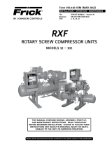
OVUR-type oil separator
OVUR 2108 HP
1517.1003 Coalescer element ø4”/ø2.5” L18”
1331.677 O-ring ø215.27 x 5.33 HNBR end cover
1331.698 O-ring ø116.84 x 5.33 HNBR coalescer element
OVUR 3209 HP
1517.177 Coalescer element ø7"/ø4" L20"
1331.604 O-ring ø329.57 x 5.33 HNBR end cover
0360023 O-ring ø229.3 x 5.7 HNBR coalescer element
OVUR 4012 HP
1517.178 Coalescer element ø9.41"/ø6.12" L30"
1331.604 O-ring ø329.57 x 5.33 HNBR end cover (only 4241–422)
1331.603 O-ring ø253.37 x 5.33 HNBR coalescer element (only 4241–422)
OVUR 5014 HP
1517.1001 Coalescer element ø11.5”/ø8.13” L34”
1331.723 O-ring ø405.26 x 5.33 HNBR end cover
1331.1000 O-ring ø315.0 x 5.33 HNBR coalescer element
OVUR 6014 HP
1517.1002 Coalescer element ø15.5”/ø11.5” L34”
1331.606 O-ring ø506.81 x 5.33 HNBR end cover
1331.2052 O-ring ø419.3 x 5.7 HNBR coalescer element
Filter
O-ring
Cross-tighten several times until achieving 10 Nm
on all three nuts. Secure with counter nut.
Bolt M8
Torque 20 Nm
O-ring

Installation, operation and maintenance manual - OVUR-type oil separator
0012381 en 2020.08 5/7
OVUR-type oil separator
Material specifications
Description Material specification
Shell P235GH/P265GH EN 10216–2/10217–2 or P275NL2 EN 10028–3;
P265GH/P295GH EN 10028–2
Nozzles P235GH/P265GH EN 10216–2/10217–2 or P275NL2 EN 10216–3/
10217–3
End cover/flange P265GH/P295GH EN 10028-2 or P275NL2 EN 10028–3
Thread nozzle P235GH/P265GH EN 10216-2/10217-2 or P250GH EN 10277-3 or
P280GH EN 10222–4 or SA333 Gr.6
Shipping
The oil separator must be blanked off and primed on delivery. The primer is not intended for out-
door storage. If the oil separator is not put into immediate service, take precautions against cor-
rosion or contamination.
Only lift the oil separator when it is empty, and make sure it is not subjected to strokes or bumps
during transport. When lifting the oil separator before it is built into the unit, always use straps
around the shell.
The weight is stated in the technical data.
A shipping description can be made when the oil separator is built together with the unit.
Installation
The site and personal protection must be in accordance with EN 378-3 or national requirements.
Check the oil separator immediately upon receipt for any damage occurred during transport. If
the oil separator is damaged, the unit must not be installed and started. When placing the oil sep-
arator, make sure to leave enough space for inspection, maintenance, escape and emergency.
Foundations must be sufficiently robust as their purpose is to provide permanent support without
settling and to absorb any normal vibrations from outside causes.
The OVUR oil separator is for vertical installation.
Blanked off branches must be cut off at the cutting groove depending on metal thickness on ad-
joining tubes. Make sure that no impurities get into the oil separator during installation.
Do not remove protective plugs and covers until immediately before installation.
The entire system must be clean before starting operation. Under certain conditions, it may be re-
quired to use strainers in the piping.
When fitting the tube connections, make sure that the load from the piping on the connections is
kept small and insignificant as the vessel is not designed to be an anchor point in the piping sys-
tem. Vibrations must be minimised, possibly by means of a vibration damper.
Apart from branch connections, welding must not be carried out on the oil separator.
The oil separator must be secured against exceeding the allowable pressures and temperatures.
All outer surfaces must have a corrosion resistant surface coating to allow the oil separator to be
installed in certain environments without it causing corrosion.

Installation, operation and maintenance manual - OVUR-type oil separator
6/7 0012381 en 2020.08
OVUR-type oil separator
Safety equipment
Before the oil separator is put into operation, it must be provided with safety equipment. The
manufacturer of the refrigeration plant is responsible for the safety equipment as it is not included
in the oil separator delivery.
Start-up and operation
Before start-up, make sure that all connections are tight.
To avoid accidents or personal injury, the person responsible for the plant must make sure that
the operating staff is duly trained and instructed before the refrigeration plant is started. The in-
struction should be based on the unit instruction manuals and should include instructions in con-
struction, supervision, operation and maintenance of the system as well as the handling of used
refrigerant.
Evacuation and charging with refrigerant must be carried out in accordance with the description
in the unit instruction manual.
Before operation, the refrigeration plant must be leak tested and inspected by an authorised
person.
Local safety and health regulations must be observed.
The authorised person makes a certificate which must be kept by the user.
Bolted connections
Normal relaxing of the gasketed joints may occur in the interval between testing at the manufac-
turer’s and installation on site. Therefore, all external bolted joints may require retightening after
installation and, if necessary, after the vessel has reached operating temperature.
It is important that all bolted joints are tightened evenly and in a diametrically staggered pattern.
All bolts must be tightened to the same torque using a torque wrench.
Maintenance
The oil separator should be inspected at the inspection intervals stated in the compressor specifi-
cation. Only qualified personnel must carry out inspection.
Operating experience will determine how often inspection of the oil separator is needed. It de-
pends on the operating conditions. Johnson Controls Denmark recommends inspection to be car-
ried out in monthly intervals during the running-in period. After a running-in period of six months,
a maintenance plan must be made. Johnson Controls Denmark recommends inspection to be car-
ried out every third month as a minimum.
Do not disconnect or tighten connections when the equipment is under pressure.
START

Installation, operation and maintenance manual - OVUR-type oil separator
0012381 en 2020.08 7/7
OVUR-type oil separator
Periodic inspection during the service life of the oil separator must meet the requirements of na-
tional legislation or EN 378-2. Correspondingly, a visual inspection of connections, outer surfaces,
bases, the vibration damper and safety equipment must be carried out.
If corrosion, erosion or other weaknesses in the oil separator are found, the oil separator must be
inspected by a qualified authorised third party, who will provide the necessary permission to con-
tinue using the oil separator. If repair is requested, approved personnel together with a qualified
third party and Johnson Controls Denmark will carry this out. If permission to continue using the
oil separator is not granted, the oil separator must be scrapped.
Disassembly for inspection or cleaning
Before disassembly, the user must make sure that the oil separator has been depressurised,
vented and drained, neutralised and/or purged of hazardous material.
Gasket connections
Gasket and gasket surface should be thoroughly cleaned and free of scratches and other defects.
The gasket should be properly positioned before attempting to retighten bolts. When an oil sepa-
rator is dismantled for any cause, it must be reassembled with new gaskets. This will prevent fur-
ther leaks and/or damage to the gasket-seating surface of the oil separator.
Spare parts and replacement parts
Spare parts and replacement parts can be ordered directly from Johnson Controls Denmark.
When ordering parts, please provide the name of the needed part as well as the oil separator seri-
al number, type, size and other information from the name plate.
Environmentally correct removal
The oil separator does not contain environmentally damaging material such as asbestos, mercury
or heavy metals.
All parts of the oil separator can be re-used after being scrapped.
• Refrigerant and oil must be drained off before destruction
• All steel materials can be used again after remelting
• During the re-melting process, coating will disappear without damaging the environment.

Johnson Controls Denmark ApS
SABROE Factory
Christian X's Vej 201 ∙ 8270 Højbjerg
Denmark
Phone +45 87 36 70 00
www.sabroe.comVersion 1
/