1/04 FORM #320
OPERATING INSTRUCTIONS
MODEL AV2A
TRMS OPEN JAW
CURRENT SENSOR
A.W. SPERRY INSTRUMENTS INC.
The Professional’s Choice®
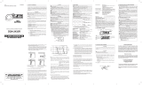
Fork Jaws
Function
Selector
Switch
Display
Data Hold/Zero
Adjustment
Button
1/04 Doc.N.320
MANUEL D’INSTRUCTIONS
MODÉLE AV2A
RMS DETECTEUR À
CIRCUIT OUVERT
A.W.SPERRY INSTRUMENTS INC.
The Professional’s Choice®
Gamme Précision FC (facteur de crête)
Gamme de
measure
ACA 0~100A ±3.o%rdg±5dgt (50/60Hz)
±2.o%rdg±5dgt (50/60Hz) CF≤2
2<CF≤2.5
Gamme Précision
Gamme de
measure
DCA 0~±100A ±2.o%rdg±5dgt
Gamme Action
Gamme de
measure
NCV 300 V CA ou
moins Conditions normales: faible Détection de tension
(fil simple, 80 V CAou plus) : forte
Fourche
Sélecteur de
fonction
Afficheur
Bouton de
maintein da
l’affichage/réglag
edu zéro
1.SAFETY WARNINGS
This instrument has been designed and tested
according to IEC Publication 61010: Safety
Requirements for Electronic Measuring Apparatus.
This instruction manual contains warnings and
safety rules which must be observed by the user
toensure safe operation of the instrument and to
retain it in safe condition. Therefore, read through
these operating instructions before using the
instrument. WARNING
•Read through and understand instructions
con tained in this manual before starting to
use the instrument.
• Save and keep the manual handy to enable
quick reference whenever necessary.
• Be sure to use the instrument only in its
intended applications.
•Be sure to understand and follow all safety
instructions contained in the manual.
•Be sure to observe above instructions.
• Failure to follow the above instructions may
cause injury, instrument damage
and/or damage to equipment under test.
The symbol indicated on the instrument
means that the user must refer to related parts in
the manual for safe operation of the instrument.
Besure to carefully read the instructions following
each symbol in this manual.
DANGER isreserved for conditions and
actions that are likely to cause serious or
fatal injury.
WARNING isreserved for conditions and
actions that can cause serious or fatal injury.
CAUTION isreserved for conditions and
actions that can cause minor injury or
instrument damage.
DANGER
•Never make measurement on the circuit
above AC/DC300V.
• Do not attempt to make measurement in the
presence of flammable gasses.
• Otherwise, the use of the instrument may
cause sparking, which can lead to an
explosion.
• Never attempt to use the instrument if its
surface or your hand is wet.
• Do not exceed the maximum allowable input
ofany measurement range.
• Do not open the battery cover and the
instrument case when making measurement.
WARNING
•Never attempt to make any measurement, if the
instrument has any structural abnormality
noted, such as cracked case or exposed metal
parts.
•Do not install substitute parts or make any
modification to the instrument. Return the
instrument to Sperry or your distributor for
repair or re-calibration.
•Do not try to replace the batteries if the surface
of the instrument is wet.
•Always switch off the instrument before opening
the battery compartment cover for battery
replacement.
CAUTION
•Always make sure to check the function
selector switch is set to the appropriate range
before starting measurement.
• Do not expose the instrument to the direct sun,
high temperature and humidity or dewfall.
•Be sure to set the function selector switch to
the “OFF” position after use. When the
instrument will not be in use for a long period,
remove batteries before placing it in storage.
•Use a cloth dipped in water or neutral detergent
for cleaning the instrument. Do not use
abrasives or solvents.
2. FEATURES
•UL listed to both US and Canadian Standards
•Limited Lifetime Warranty
•4Ranges, 3 Functions
•True RMS AC Current
•100AAC/DC Current Capability
•NCV Function (Non Contact Voltage)
•Data Hold
•Auto Power Off
3. SPECIFICATIONS
ACCurrent ~A
DC Current A
AC Voltage ~V
Note:NCV range is calibrated to detect the
voltage, where non-grounded single wire, AC80V
ormore. However, detecting sensitivity may
beaffected by the absence of grounded or
non-grounded metal tube or metal case. Also it
may be affected in the place where influenced by
other voltages, how you grip the instrument or the
measuring position of sensor.
•CF(Crest Factor): CF=2.5 or less
•Standards: IEC61010-1, IEC61010-2-032
Overvoltage CATIII 300V, pollution degree 2
Installation Category II, pollution degree 2
Altitude up to 2000 meters. Indoor use.
IEC61326 (EMC standard)
•Indication: LCD Max. 1049 units, symbols
• Over range display: “OL” symbol is displayed
onthe LCD.(Only on current range)
•Response time: Approx. 2sec.
•Sampling rate: Approx. twice per second
•Temperature & Humidity range: 23°±5°
• Relative humidity: 75% or less
(no condensation)(guaranteed accuracy)
• Operating Temperature & Humidity range:
41° to 104F, 5° to 40°
• Relative humidity: 85% or less
(no condensation)
•Storage Temperature & Humidity range:
-4° to 140F, -20° to 60°
•Relative humidity: 85% or less
(no condensation)
•Power source: DC3V : R03(UM-4)x2pcs
• Current consumption: Approx.12mA or less
Todecrease current consumption, detecting
circuit is on only for 0.1/0.5sec.
•Power off function: Approximately 10 min.
•Overload Protection: AC/DC current : AC/DC
120A/ 10sec. AC voltage (NCV) : AC360V/
10sec.
• Withstand Voltage: AC3700V/ for one min.
(Between electrical circuit and enclosures.)
• Insulation Resistance: 10MΩ/1000V
(Between electrical circuit and enclosures.)
Double Insulation.
•Max. diameter of measured object:
Max. 0.4” (10mm)
• Dimensions: 6.4”(L) x 1.6”(W) x 1.2”(D)
(161.3 x 40.2 x 30.3 mm)
• Weight: 3.9oz (110g) including batteries
•Accessories: Battery R03, (AAAAWS
Part # B-7 (2)
Instruction manual (1)
Carrying case (1)
REFERENCE
*Effective Value (RMS)
Most alternating currents and voltages are
expressed in effective values, which are also
referred to as RMS (Root-Mean-Square) values.
The effective value is the square root of the
average of square of alternating current or voltage
values. Many clamp meters using a conventional
rectifying circuit have “RMS” scales for AC
measurement. The scales are, however, actually
calibrated in terms of the effective value of a sine
wave though the clamp meter is responding to the
average value. The calibration is done with a
conversion factor of 1.111 for sine wave, which is
found by dividing the effective value by the
average value. These instruments are therefore in
error if the input voltage or current has some other
shape than sine wave.
*CF (Crest Factor) is found by dividing the peak
value by the effective value.
Examples:
Sine wave: CF=1.414
Square wave with a 1: 4 duty ratio: CF=2
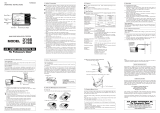
4.DISPLAY
5.PREPARATION
Check battery voltage.
Set the Function selector switch to the position
other than OFF position.
Battery Voltage is enough if indications are
displayed clearly and “BATT” mark is not
displayed on the LCD. If “BATT” mark is
indicated or no indication on the LCD, replace
batteries with new one according to battery
replacement procedures shown in clause 8 in
this document.
CAUTION
• Indications may not being displayed on the
LCD despite the function selector switch is at
the position other than OFF position. This is
because power-off function operated
automatically and the instrument turned off.
• Power off function can be released by turning
the function selector switch to OFF, and then
set it to the range on which you would like to
make a measurement. If LCD still blank,
batteries are completely exhausted. Please
replace batteries.
•Check the function selector switch is set to the
appropriate range. And also check data hold
function is not enabled. If inappropriate range is
selected, desired measurement cannot be
made.
6.MEASUREMENTS
6-1 Current Measurement
DANGER
•To avoid getting an electrical shock, never make
measurement on the circuit in which electrical
potential over AC/DC300V exists. Do not make
measurement with battery cover removed.
CAUTION
Max. diameter of measured object(conductor) is Ø
10mm.
6-1-1 DC current measurement
1-Set the function selector switch to “ A ”
position. (“ ” and “A” marks will be displayed
onthe LCD.)
2-Press HOLD/0ADJ button for 2 sec or more to
enable 0ADJ function and adjust the indication
onthe LCD to be 0. (Indication shall be
adjusted to 0. Otherwise, error occurs.)
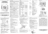
3-Place one measured conductor lower than the
triangle mark indicated on the fork shaped
sensor and make a measurement. (shaded part
in the figure)
Then measured value is displayed on the LCD.
(When the center of the conductor is not lower
than the triangle mark indicated on the fork
shaped sensor, error occurs.)
Note: When current is flowing from the upside
to the underside of the instrument, reading is
positive(+), on the contrary, reading to be
negative(-) when current is flowing from the
underside to the upside of the instrument.
6-1-2 AC current measurement
1-Set the function selector switch to “A”
position. (“ ” and “A” marks will be
displayed on the LCD.)
2-Place one measured conductor lower than the
triangle mark indicated on the fork shaped
sensor and make a measurement. (shaded part
inthe figure)
Then measured value is displayed on the LCD.
(When the center of the conductor is not lower
than the triangle mark indicated on the fork
shaped sensor, error occurs.)
Note: For the measurement of AC current, zero
adjustment, which is required for the
measurement of DC current, is not necessary.
Current flowing direction has no relation to the
indication polarity.
6-2 Non contact voltage detection(NCV)
This function is to check the presence of
voltage without touching wires or electrodes
directly. Also can check the presence of AC
voltage in cable, outlet, fuse and circuit breaker.
Details:
While voltage is applied to a cable or outlet,
the electric field depending on the voltage is
generated. This instrument detects the
generated electric field, and verifies the
presence of AC voltage. Officially, it is called as
an instrument for detecting electrical field. But it
isnot a familiar term, so we call it as “Non
contact voltage detection”. General detectors
detect voltage by contacting polarized voltage
(contacts and terminals). But this instrument is
developed to satisfy this function and for safety
purpose with out contacting voltage.
DANGER
• To avoid getting an electrical shock, never
make measurement on the circuit in which
electrical potential over AC/DC300V exists.
• Before a measurement, be sure to check the
instrument operation with well-known power
supply. If “ Err ” is displayed on the LCD, do not
make a measurement.
• Do not make measurement with battery cover
removed. Indicated value on NCV range is a
reference value. Make sure to check the
voltage with a precise equipment in advance
when operator will directly touch or connect
wires.
•Indicated voltage value may be affected by
non-grounded metal tube or metal case, the
place where affected by other voltages,
handgrip or the measuring position of sensor.
6-2-1 Measurements
•Set the function selector switch to “NCV”
position.
•The sensing mode (100V or 200V) in effect is
displayed on the LCD for 1min, and NCV
measurement starts.
•Position the tip part of fork typed sensor
against the measured object. When voltage is
detected, “ Hi ” will be displayed on the LCD.
(Error could occur depending on the direction,
angle and contact surface of the instrument
against the measured object. On NCV range,
data hold function cannot be used.)
Note: When set the function selector switch to
NCV range, self-check function operates and
Indicates “ Err ”, if there is some fault or
abnormal condition. Do not make a
measurement if such indication displayed on
the LCD.
6-2-2 Sensing mode
•There are two types of sensing mode: 100V
mode and 200V mode.
•Above two modes can be changed over by
pressing the data hold button 2sec or more.
(The selected sensing mode is stored even if
switching off the instrument. When setting the
function switch to “NCV” again, measurement
can be done on the same mode.)
• Factory setting: 100V mode
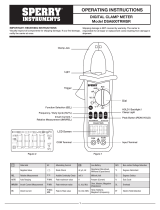
1-100V mode
Sensitivity on this mode is set sharp, therefore,
the presence of AC voltage can be checked
only by placing the instrument closer to the
measured object, such as an outlet, a plug and
parallel cords, as shown in figure.
2- 200V mode
Sensitivity on this mode is set dull, so the earth
side and non-earth side of 100V cable way can
beverified. (Where cables are crowded, such
asin a distribution board, earth side could not
be verified.) Also can check the presence of AC
voltage in 200V cable way, plug, outlet, fuse
and circuit breaker.
7. OTHER FUNCTIONS
7-1 Auto power off function
This is a function to prevent the instrument
from being left powered on in order to conserve
battery life. This function causes the instrument
to automatically enter the power-off mode about
10min after the last function selector switch
operation. To exit the power-off mode and make
new measurement, turn the function selector
switch back to “OFF”, then to any other
position.
7-2 Data hold function
This is a function to hold the measured value
on the LCD. Press the data hold button to hold
the reading. The reading will be held regardless
of subsequent changes in input. “H” mark is
shown on the LCD while the instrument is in
the data hold mode. To exit the data hold
mode, press the data hold button again.
7-3 '0' Adj. function (Zero adjustment function)
When pressing the data hold button for over
2sec before making a measurement,
indications on the LCD can be adjusted to 0.
8. BATTERY REPLACEMENT
WARNING
To avoid getting electrical shock, be sure to set
the function selector switch to “OFF” position
before trying to replace the batteries.
CAUTION
•Do not mix new and old batteries.
•Make sure to install battery in correct polarity
as indicated inside the battery cover.
When “BATT” mark is shown on the upper left
corner of the LCD, replace the batteries.
Note that if the battery is completely exhausted,
the LCD blanks without “BATT” mark shown.
1- Set the function selector switch to “OFF”
position.
2- Unscrew and remove the battery cover on the
bottom of the instrument.
3-Replace the batteries. (Two R03 (AAA)
batteries)
4- Mount and screw the battery cover.
LIFETIME LIMITED WARRANTY
The attention to detail of this fine snap-around
instrument is further enhanced by the application of
A.W. Sperry’s unmatched service and concern for
detail and reliability. These A.W. Sperry’s snap-
arounds are internationally accepted by craftsmen
and servicemen for their unmatched performance.
All A.W. Sperry’s snap-around instruments are
unconditionally warranted against defects in material
and workmanship under normal conditions of
use and service; our obligations under this warranty
being limited to repairing or replacing, free of
charge, at A.W. Sperry’s sole option, any such
A.W. Sperry snap-around instrument that
malfunctions under normal operating conditions at
rated use 1.
REPLACEMENT PROCEDURE
Securely wrap the instrument and its accessories in
abox or mailing bag and ship prepaid to the
address below.Be sure to include your name and
address, as well as the name of the distributor, with
acopy of your invoice from whom the unit was
purchased, clearly identifying the model number and
the date of purchase.
A.W.SPERRY INSTRUMENT INC.
ATTN: Customer Service Dept.
245 Marcus Boulevard
Hauppauge, N.Y. 11788-2075
1. Warranty is not applicable if the instrument has
been: misused, abused, subjected to loads in
excess of specifications, has had unauthorized
repair or has been improperly assembled or
used.
*Note: Recommended calibration interval should not
exceed one year. Calibration service charges are
not covered under terms and conditions of
warranty.
1.AVERTISSEMENTS DE SÉCURITÉ
L’appareil visé par le présent manuel
d’instructions a été conçu et essayé
conformément aux dispositions de la publica
tion 61010 de la CEI sur la sécurité des dis
positifs électroniques de mesure. Ce manuel
contient des avertissements et règles de sécu
rité que l’utilisateur doit observer pour garantir
un usage sans danger de l’appareil et lui garder
toute sa sécurité. Veuillez par conséquent lire
entièrement le présent mode d’emploi avant de
commencer à vous servir de l’appareil.
AVERTISSEMENT
• Parcourez et assurez-vous de bien comprendre
les instructions présentées dans le présent
manuel avant de commencer à utiliser votre
appareil.
•Conservez le manuel à portée de main pour
pouvoir le consulter facilement à chaque fois
que cela vous est nécessaire.
• N’utilisez l’appareil que pour les usages aux
quels il est destiné.
•Assurez-vous de bien comprendre et de suivre
toutes les consignes de sécurité exposées
dans le manuel.
• Observez rigoureusement les instructions
ci-dessus.
• Tout manquement à suivre les instructions
ci-dessus peut entraîner des blessures person
nelles ainsi que des dommages tant à
l’appareil qu’au matériel soumis aux essais.
Le symbole figurant sur l’appareil signifie
que l’utilisateur doit se reporter aux parties
appropriées du manuel pour utiliser ledit
appareil de façon sécuritaire. Lisez très
attentivement les instructions placées, dans le
manuel, à côté du symbole.
DANGER est réservé aux situations et actions
ayant une forte probabilité de causer des
blessures graves ou mortelles.
AVERTISSEMENT est réservé aux situations
et actions susceptibles de causer des blessures
graves ou mortelles.
ATTENTION est réservé aux situations et
actions pouvant causer des blessures légères
ou endommager l’appareil.
DANGER
•N’effectuez jamais de mesures sur des circuits
électriques dont la tension excède 300 V en
CA ou CC.
• Ne tentez jamais d’effectuer des mesures à
proximité de gaz inflammables: l’utilisation de
l’appareil peut causer une étincelle susceptible
d’entraîner une explosion.
• N’essayez jamais d’utiliser l’appareil lorsque
sa surface ou lorsque votre main est humide.
• Ne dépassez pas l’entrée maximale autorisée
dans chaque gamme de mesure.
•N’ouvrez pas le couvercle du compartiment des
piles ou le corps de l’instrument pendant une
mesure.
AVERTISSEMENT
•N’essayez jamais d’effectuer une mesure
lorsque vous remarquez une anomalie dans la
structure de l’appareil, comme une fissure du
boîtier ou la présence de parties métalliques
dénudées.
• Ne montez aucune pièce de rechange et n’ef
fectuez aucune modification sur l’appareil.
Retournez ce dernier à Sperry ou à votre reven
deur pour le faire réparer ou recalibrer.
• N’essayez pas de remplacer les piles lorsque la
surface de l’appareil est humide.
•Mettez toujours l’appareil hors tension avant
d’ouvrir le compartiment des piles pour changer
ces dernières.
ATTENTION
• Assurez-vous toujours que le sélecteur de
fonction est placé sur la gamme appropriée
avant d’entreprendre une mesure.
• N’exposez pas l’appareil en plein soleil, à des
températures élevées, à l’humidité ou à la
rosée.
•Veiller à toujours ramener le sélecteur de
fonction en position « OFF » après usage. Si
vous ne devez pas utiliser l’appareil durant une
période prolongée, retirez les piles avant de le
ranger.
• Utilisez un chiffon humidifié avec de l’eau ou un
détergeant neutre pour nettoyer l’appareil.
• N’utilisez ni abrasifs, ni solvants.
2. CARACTÉRISTIQUES
Homologué UL selon les normes canadiennes
et américaines
Garantie limitée à vie
Quatre gammes de mesure, trois fonctions
Courant alternatif RMS vrai
Intensité maximale CA/CC 100 A
Fonction de détection de tension sans contact
(NCV)
Maintien de l’affichage
Mise hors tension automatique
3.DONNÉES TECHNIQUES
Courant CAA
Courant CC A
Tension CA V
Remarque: la gamme NCV est calibrée pour
détecter les tensions de 80 V CA et plus, dans
des installations avec fil simple sans mise à la
terre. La sensibilité de détection peut cependant
être affectée par l’absence de tube en métal ou
de boîtier métallique relié ou non à la terre. Elle
peut en outre être influencée par d’autres ten
sions existant au même endroit, par la manière
de tenir l’appareil ou par la position du capteur
lors de la mesure.
• FC (facteur de crête): FC = 2,5 ou moins
Normes: CEI61010-1, CEI61010-2-032
Protection c. surtensions 300 V CATIII, degré
de pollution 2 Catégorie d’installation II, degré
de pollution 2 Altitude 2 000 m maximum
Utilisation à l’intérieur CEI61326 (Norme CEM)
•Affichage: ACL, 1049 unités max., symboles
•Affichage du dépassement: Le symbole
«OL » s’affiche sur l’ACL de gamme
(seulement dans la gamme en cours
d’utilisation)
•Temps de réponse: Env.2secondes
•Taux d’échantillonnage: Env.deux fois par
seconde
•Plages de température: 23°C±5°C
•et d’humidité: Humidité relative: 75 % ou
moins (sans condensation) (précision garantie)
•Plages de température: 41 à 104° F, 5 à
40° C
•et d’humidité: Humidité relative : 85 % ou
moins (sans condensation)
•Plages de température: -4 à 140° F, -20 à
60° C
•et d’humidité pour l’entreposage:
Humidité relative: 85 % ou moins
(sans condensation)
•Alimentation: 3VCC: 2 piles R03 (UM-4)
•Consommation électrique: Env.12 mA ou
moins. Afin de réduire la consommation, le cir
cuit de détection ne s’active que pendant 0,1 à
0,5 seconde.
•Fonction de mise hors tension: Env. 10 mn
•Protection contre les surcharges:
Courant CA/CC : 120 A CA/CC pendant
10 secondes. Tension CA (NCV) : 360 V CA
pendant 10 secondes
•Tension de tenue: 3700 V CA pendant
une minute (entre le circuit électrique et
les coffrets)
•Résistance d’isolement: 10 MΩ/1000 V
(entre le circuit électrique et les coffrets)
Isolement double
•Diamètre maxi. des objets sur lesquels
effectuer la mesure: 10 mm maximum
•Dimensions: 161,3 (L) x 40,2 (l) x 30,3
(P) mm
•Poids: 110 g, y compris les piles
•Accessoires: Piles R03 (AAAAWS Partie
B-7 (2). Manuel d’instructions (1)
Coffret de transport (1)
RÉFÉRENCES
•Valeur efficace (RMS)
La plupart des tensions et des courants
alternatifs s’expriment en valeur efficace, que
l’on appelle également la valeur RMS. La
valeur efficace est équivalente à la racine car
rée de la moyenne des valeurs de la tension
ou du courant alternatifs. De nombreux multi
mètres équipés d’un circuit redresseur
conventionnel possèdent des échelles «RMS»
pour mesurer le courant alternatif. Toutefois,
ces échelles sont en réalité calibrées en
fonction de la valeur effective de la sinusoïde
bien que le multimètre réponde à la valeur
moyenne. La calibration s’effectue pour la
sinusoïde selon un facteur de conversion de
1,111, qui se calcule en divisant la valeur
efficace par la valeur moyenne. Ces appareils
fournissent dès lors des mesures erronées si
la forme de la tension ou du courant d’entrée
n’est pas sinusoïdale.
•Facteur de crête (FC): cette valeur se calcule
en divisant la valeur de crête par la valeur
efficace.
Exemples :
Onde sinusoïdale : FC = 1,414
Onde carrée avec un facteur de marche
1à4: FC= 2
4. AFFICHEUR
A- CA/CC
B- Mode maintien da l’affichage
C- Unité
D- Gamme NCV
E- Indicateur de décharge des piles
5. PRÉPARATION
1- Vérifiez la tension des piles. Placez le sélecteur
de fonction sur une position autre que OFF. La
tension des piles est suffisante si les indications
apparaissent clairement sur l’afficheur et si la
mention BATT n’est pas visible. Si la mention
“BATT ” appa raît ou si aucune indication ne
s’affiche sur l’ACL, rem placez les piles en suiv
ant la procé dure décrite à la section 8 du
présent document.
ATTENTION
•lse peut que l’ACL n’affiche aucune indica
tion bien que le sélecteur de fonction soit sur
une position autre que OFF.
•Cela se produit lorsque la fonction de mise
hors tension automatique a éteint l’appareil.
• Pour remettre l’appareil sous tension, ramenez
le sélecteur de fonction en position OFF, puis
tournez-le pour le placer sur la gamme dans
laquelle vous souhaitez effectuer une mesure.
•Si l’ACL reste vide, les piles sont complète
ment déchargées. Vous devez alors les rem
placer.
2- Assurez-vous que le sélecteur de fonction
est placé sur la gamme appropriée. Vérifiez
également que la fonction de maintien de l’af
fichage n’est pas activée. Vous ne pourrez
pas effectuer la mesure que vous désirez si
vous sélectionnez une gamme non appr priée.
!
!
!
!
!
!
!
!
!
!
!
!
!
!
!
!
!
!
!
!
!
Range Accuracy CF(Crest factor)
Measuring Range
ACA 0~100A ±3.0%rdg±5dgt (50/60Hz)
±2.0%rdg±5dgt (50/60Hz) CF≤2
2<CF≤2.5
Range Accuracy
Measuring Range
DCA 0~±100A ±2.0%rdg±5dgt
Range Action
Measuring Range
NCV AC30V or less Normal condition: Lo At voltage detecting
(single wire AC80V or more) Hi
!
!
!
!
A.W.SPERRYINSTRUMENTS INC.
The Professional’sChoice®
245 Marcus Blvd., Hauppauge, NY 11788
Fax: 631-434-3128
Email: cat@awsperry.com
http//:www.awsperry.com
–
---
1.8.8.8H
X
~
=
–
BATT
NCV
A
E
B
C
D
1.8.8.8
H
X
~
=
–
BATT
NCV
AC/DC
Low
Battery
Warning
Unit
NCV Range
Data
Hold
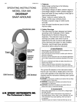
Mode Place the center of the metal conductor lower than the
triangle mark indicated on the fork shaped sensor.
(shaded part in the figure)
–
---
–
---
Correct Incorrect

1/04 FORM #320
OPERATING INSTRUCTIONS
MODEL AV2A
TRMS OPEN JAW
CURRENT SENSOR
A.W. SPERRY INSTRUMENTS INC.
The Professional’s Choice®
Fork Jaws
Function
Selector
Switch
Display
Data Hold/Zero
Adjustment
Button
1/04 Doc.N.320
MANUEL D’INSTRUCTIONS
MODÉLE AV2A
RMS DETECTEUR À
CIRCUIT OUVERT
A.W.SPERRY INSTRUMENTS INC.
The Professional’s Choice®
Gamme Précision FC (facteur de crête)
Gamme de
measure
ACA 0~100A ±3.o%rdg±5dgt (50/60Hz)
±2.o%rdg±5dgt (50/60Hz) CF≤2
2<CF≤2.5
Gamme Précision
Gamme de
measure
DCA 0~±100A ±2.o%rdg±5dgt
Gamme Action
Gamme de
measure
NCV 300 V CA ou
moins Conditions normales: faible Détection de tension
(fil simple, 80 V CAou plus) : forte
Fourche
Sélecteur de
fonction
Afficheur
Bouton de
maintein da
l’affichage/réglag
edu zéro
1.SAFETY WARNINGS
This instrument has been designed and tested
according to IEC Publication 61010: Safety
Requirements for Electronic Measuring Apparatus.
This instruction manual contains warnings and
safety rules which must be observed by the user
toensure safe operation of the instrument and to
retain it in safe condition. Therefore, read through
these operating instructions before using the
instrument. WARNING
•Read through and understand instructions
con tained in this manual before starting to
use the instrument.
• Save and keep the manual handy to enable
quick reference whenever necessary.
• Be sure to use the instrument only in its
intended applications.
•Be sure to understand and follow all safety
instructions contained in the manual.
•Be sure to observe above instructions.
• Failure to follow the above instructions may
cause injury, instrument damage
and/or damage to equipment under test.
The symbol indicated on the instrument
means that the user must refer to related parts in
the manual for safe operation of the instrument.
Besure to carefully read the instructions following
each symbol in this manual.
DANGER isreserved for conditions and
actions that are likely to cause serious or
fatal injury.
WARNING isreserved for conditions and
actions that can cause serious or fatal injury.
CAUTION isreserved for conditions and
actions that can cause minor injury or
instrument damage.
DANGER
•Never make measurement on the circuit
above AC/DC300V.
• Do not attempt to make measurement in the
presence of flammable gasses.
• Otherwise, the use of the instrument may
cause sparking, which can lead to an
explosion.
• Never attempt to use the instrument if its
surface or your hand is wet.
• Do not exceed the maximum allowable input
ofany measurement range.
• Do not open the battery cover and the
instrument case when making measurement.
WARNING
•Never attempt to make any measurement, if the
instrument has any structural abnormality
noted, such as cracked case or exposed metal
parts.
•Do not install substitute parts or make any
modification to the instrument. Return the
instrument to Sperry or your distributor for
repair or re-calibration.
•Do not try to replace the batteries if the surface
of the instrument is wet.
•Always switch off the instrument before opening
the battery compartment cover for battery
replacement.
CAUTION
•Always make sure to check the function
selector switch is set to the appropriate range
before starting measurement.
• Do not expose the instrument to the direct sun,
high temperature and humidity or dewfall.
•Be sure to set the function selector switch to
the “OFF” position after use. When the
instrument will not be in use for a long period,
remove batteries before placing it in storage.
•Use a cloth dipped in water or neutral detergent
for cleaning the instrument. Do not use
abrasives or solvents.
2. FEATURES
•UL listed to both US and Canadian Standards
•Limited Lifetime Warranty
•4Ranges, 3 Functions
•True RMS AC Current
•100AAC/DC Current Capability
•NCV Function (Non Contact Voltage)
•Data Hold
•Auto Power Off
3. SPECIFICATIONS
ACCurrent ~A
DC Current A
AC Voltage ~V
Note:NCV range is calibrated to detect the
voltage, where non-grounded single wire, AC80V
ormore. However, detecting sensitivity may
beaffected by the absence of grounded or
non-grounded metal tube or metal case. Also it
may be affected in the place where influenced by
other voltages, how you grip the instrument or the
measuring position of sensor.
•CF(Crest Factor): CF=2.5 or less
•Standards: IEC61010-1, IEC61010-2-032
Overvoltage CATIII 300V, pollution degree 2
Installation Category II, pollution degree 2
Altitude up to 2000 meters. Indoor use.
IEC61326 (EMC standard)
•Indication: LCD Max. 1049 units, symbols
• Over range display: “OL” symbol is displayed
onthe LCD.(Only on current range)
•Response time: Approx. 2sec.
•Sampling rate: Approx. twice per second
•Temperature & Humidity range: 23°±5°
• Relative humidity: 75% or less
(no condensation)(guaranteed accuracy)
• Operating Temperature & Humidity range:
41° to 104F, 5° to 40°
• Relative humidity: 85% or less
(no condensation)
•Storage Temperature & Humidity range:
-4° to 140F, -20° to 60°
•Relative humidity: 85% or less
(no condensation)
•Power source: DC3V : R03(UM-4)x2pcs
• Current consumption: Approx.12mA or less
Todecrease current consumption, detecting
circuit is on only for 0.1/0.5sec.
•Power off function: Approximately 10 min.
•Overload Protection: AC/DC current : AC/DC
120A/ 10sec. AC voltage (NCV) : AC360V/
10sec.
• Withstand Voltage: AC3700V/ for one min.
(Between electrical circuit and enclosures.)
• Insulation Resistance: 10MΩ/1000V
(Between electrical circuit and enclosures.)
Double Insulation.
•Max. diameter of measured object:
Max. 0.4” (10mm)
• Dimensions: 6.4”(L) x 1.6”(W) x 1.2”(D)
(161.3 x 40.2 x 30.3 mm)
• Weight: 3.9oz (110g) including batteries
•Accessories: Battery R03, (AAAAWS
Part # B-7 (2)
Instruction manual (1)
Carrying case (1)
REFERENCE
*Effective Value (RMS)
Most alternating currents and voltages are
expressed in effective values, which are also
referred to as RMS (Root-Mean-Square) values.
The effective value is the square root of the
average of square of alternating current or voltage
values. Many clamp meters using a conventional
rectifying circuit have “RMS” scales for AC
measurement. The scales are, however, actually
calibrated in terms of the effective value of a sine
wave though the clamp meter is responding to the
average value. The calibration is done with a
conversion factor of 1.111 for sine wave, which is
found by dividing the effective value by the
average value. These instruments are therefore in
error if the input voltage or current has some other
shape than sine wave.
*CF (Crest Factor) is found by dividing the peak
value by the effective value.
Examples:
Sine wave: CF=1.414
Square wave with a 1: 4 duty ratio: CF=2
4.DISPLAY
5.PREPARATION
Check battery voltage.
Set the Function selector switch to the position
other than OFF position.
Battery Voltage is enough if indications are
displayed clearly and “BATT” mark is not
displayed on the LCD. If “BATT” mark is
indicated or no indication on the LCD, replace
batteries with new one according to battery
replacement procedures shown in clause 8 in
this document.
CAUTION
• Indications may not being displayed on the
LCD despite the function selector switch is at
the position other than OFF position. This is
because power-off function operated
automatically and the instrument turned off.
• Power off function can be released by turning
the function selector switch to OFF, and then
set it to the range on which you would like to
make a measurement. If LCD still blank,
batteries are completely exhausted. Please
replace batteries.
•Check the function selector switch is set to the
appropriate range. And also check data hold
function is not enabled. If inappropriate range is
selected, desired measurement cannot be
made.
6.MEASUREMENTS
6-1 Current Measurement
DANGER
•To avoid getting an electrical shock, never make
measurement on the circuit in which electrical
potential over AC/DC300V exists. Do not make
measurement with battery cover removed.
CAUTION
Max. diameter of measured object(conductor) is Ø
10mm.
6-1-1 DC current measurement
1-Set the function selector switch to “ A ”
position. (“ ” and “A” marks will be displayed
onthe LCD.)
2-Press HOLD/0ADJ button for 2 sec or more to
enable 0ADJ function and adjust the indication
onthe LCD to be 0. (Indication shall be
adjusted to 0. Otherwise, error occurs.)
3-Place one measured conductor lower than the
triangle mark indicated on the fork shaped
sensor and make a measurement. (shaded part
in the figure)
Then measured value is displayed on the LCD.
(When the center of the conductor is not lower
than the triangle mark indicated on the fork
shaped sensor, error occurs.)
Note: When current is flowing from the upside
to the underside of the instrument, reading is
positive(+), on the contrary, reading to be
negative(-) when current is flowing from the
underside to the upside of the instrument.
6-1-2 AC current measurement
1-Set the function selector switch to “A”
position. (“ ” and “A” marks will be
displayed on the LCD.)
2-Place one measured conductor lower than the
triangle mark indicated on the fork shaped
sensor and make a measurement. (shaded part
inthe figure)
Then measured value is displayed on the LCD.
(When the center of the conductor is not lower
than the triangle mark indicated on the fork
shaped sensor, error occurs.)
Note: For the measurement of AC current, zero
adjustment, which is required for the
measurement of DC current, is not necessary.
Current flowing direction has no relation to the
indication polarity.
6-2 Non contact voltage detection(NCV)
This function is to check the presence of
voltage without touching wires or electrodes
directly. Also can check the presence of AC
voltage in cable, outlet, fuse and circuit breaker.
Details:
While voltage is applied to a cable or outlet,
the electric field depending on the voltage is
generated. This instrument detects the
generated electric field, and verifies the
presence of AC voltage. Officially, it is called as
an instrument for detecting electrical field. But it
isnot a familiar term, so we call it as “Non
contact voltage detection”. General detectors
detect voltage by contacting polarized voltage
(contacts and terminals). But this instrument is
developed to satisfy this function and for safety
purpose with out contacting voltage.
DANGER
• To avoid getting an electrical shock, never
make measurement on the circuit in which
electrical potential over AC/DC300V exists.
• Before a measurement, be sure to check the
instrument operation with well-known power
supply. If “ Err ” is displayed on the LCD, do not
make a measurement.
• Do not make measurement with battery cover
removed. Indicated value on NCV range is a
reference value. Make sure to check the
voltage with a precise equipment in advance
when operator will directly touch or connect
wires.
•Indicated voltage value may be affected by
non-grounded metal tube or metal case, the
place where affected by other voltages,
handgrip or the measuring position of sensor.
6-2-1 Measurements
•Set the function selector switch to “NCV”
position.
•The sensing mode (100V or 200V) in effect is
displayed on the LCD for 1min, and NCV
measurement starts.
•Position the tip part of fork typed sensor
against the measured object. When voltage is
detected, “ Hi ” will be displayed on the LCD.
(Error could occur depending on the direction,
angle and contact surface of the instrument
against the measured object. On NCV range,
data hold function cannot be used.)
Note: When set the function selector switch to
NCV range, self-check function operates and
Indicates “ Err ”, if there is some fault or
abnormal condition. Do not make a
measurement if such indication displayed on
the LCD.
6-2-2 Sensing mode
•There are two types of sensing mode: 100V
mode and 200V mode.
•Above two modes can be changed over by
pressing the data hold button 2sec or more.
(The selected sensing mode is stored even if
switching off the instrument. When setting the
function switch to “NCV” again, measurement
can be done on the same mode.)
• Factory setting: 100V mode
1-100V mode
Sensitivity on this mode is set sharp, therefore,
the presence of AC voltage can be checked
only by placing the instrument closer to the
measured object, such as an outlet, a plug and
parallel cords, as shown in figure.
2- 200V mode
Sensitivity on this mode is set dull, so the earth
side and non-earth side of 100V cable way can
beverified. (Where cables are crowded, such
asin a distribution board, earth side could not
be verified.) Also can check the presence of AC
voltage in 200V cable way, plug, outlet, fuse
and circuit breaker.
7. OTHER FUNCTIONS
7-1 Auto power off function
This is a function to prevent the instrument
from being left powered on in order to conserve
battery life. This function causes the instrument
to automatically enter the power-off mode about
10min after the last function selector switch
operation. To exit the power-off mode and make
new measurement, turn the function selector
switch back to “OFF”, then to any other
position.
7-2 Data hold function
This is a function to hold the measured value
on the LCD. Press the data hold button to hold
the reading. The reading will be held regardless
of subsequent changes in input. “H” mark is
shown on the LCD while the instrument is in
the data hold mode. To exit the data hold
mode, press the data hold button again.
7-3 '0' Adj. function (Zero adjustment function)
When pressing the data hold button for over
2sec before making a measurement,
indications on the LCD can be adjusted to 0.
8. BATTERY REPLACEMENT
WARNING
To avoid getting electrical shock, be sure to set
the function selector switch to “OFF” position
before trying to replace the batteries.
CAUTION
•Do not mix new and old batteries.
•Make sure to install battery in correct polarity
as indicated inside the battery cover.
When “BATT” mark is shown on the upper left
corner of the LCD, replace the batteries.
Note that if the battery is completely exhausted,
the LCD blanks without “BATT” mark shown.
1- Set the function selector switch to “OFF”
position.
2- Unscrew and remove the battery cover on the
bottom of the instrument.
3-Replace the batteries. (Two R03 (AAA)
batteries)
4- Mount and screw the battery cover.
LIFETIME LIMITED WARRANTY
The attention to detail of this fine snap-around
instrument is further enhanced by the application of
A.W. Sperry’s unmatched service and concern for
detail and reliability. These A.W. Sperry’s snap-
arounds are internationally accepted by craftsmen
and servicemen for their unmatched performance.
All A.W. Sperry’s snap-around instruments are
unconditionally warranted against defects in material
and workmanship under normal conditions of
use and service; our obligations under this warranty
being limited to repairing or replacing, free of
charge, at A.W. Sperry’s sole option, any such
A.W. Sperry snap-around instrument that
malfunctions under normal operating conditions at
rated use 1.
REPLACEMENT PROCEDURE
Securely wrap the instrument and its accessories in
abox or mailing bag and ship prepaid to the
address below.Be sure to include your name and
address, as well as the name of the distributor, with
acopy of your invoice from whom the unit was
purchased, clearly identifying the model number and
the date of purchase.
A.W.SPERRY INSTRUMENT INC.
ATTN: Customer Service Dept.
245 Marcus Boulevard
Hauppauge, N.Y. 11788-2075
1. Warranty is not applicable if the instrument has
been: misused, abused, subjected to loads in
excess of specifications, has had unauthorized
repair or has been improperly assembled or
used.
*Note: Recommended calibration interval should not
exceed one year. Calibration service charges are
not covered under terms and conditions of
warranty.
1.AVERTISSEMENTS DE SÉCURITÉ
L’appareil visé par le présent manuel
d’instructions a été conçu et essayé
conformément aux dispositions de la publica
tion 61010 de la CEI sur la sécurité des dis
positifs électroniques de mesure. Ce manuel
contient des avertissements et règles de sécu
rité que l’utilisateur doit observer pour garantir
un usage sans danger de l’appareil et lui garder
toute sa sécurité. Veuillez par conséquent lire
entièrement le présent mode d’emploi avant de
commencer à vous servir de l’appareil.
AVERTISSEMENT
• Parcourez et assurez-vous de bien comprendre
les instructions présentées dans le présent
manuel avant de commencer à utiliser votre
appareil.
•Conservez le manuel à portée de main pour
pouvoir le consulter facilement à chaque fois
que cela vous est nécessaire.
• N’utilisez l’appareil que pour les usages aux
quels il est destiné.
•Assurez-vous de bien comprendre et de suivre
toutes les consignes de sécurité exposées
dans le manuel.
• Observez rigoureusement les instructions
ci-dessus.
• Tout manquement à suivre les instructions
ci-dessus peut entraîner des blessures person
nelles ainsi que des dommages tant à
l’appareil qu’au matériel soumis aux essais.
Le symbole figurant sur l’appareil signifie
que l’utilisateur doit se reporter aux parties
appropriées du manuel pour utiliser ledit
appareil de façon sécuritaire. Lisez très
attentivement les instructions placées, dans le
manuel, à côté du symbole.
DANGER est réservé aux situations et actions
ayant une forte probabilité de causer des
blessures graves ou mortelles.
AVERTISSEMENT est réservé aux situations
et actions susceptibles de causer des blessures
graves ou mortelles.
ATTENTION est réservé aux situations et
actions pouvant causer des blessures légères
ou endommager l’appareil.
DANGER
•N’effectuez jamais de mesures sur des circuits
électriques dont la tension excède 300 V en
CA ou CC.
• Ne tentez jamais d’effectuer des mesures à
proximité de gaz inflammables: l’utilisation de
l’appareil peut causer une étincelle susceptible
d’entraîner une explosion.
• N’essayez jamais d’utiliser l’appareil lorsque
sa surface ou lorsque votre main est humide.
• Ne dépassez pas l’entrée maximale autorisée
dans chaque gamme de mesure.
•N’ouvrez pas le couvercle du compartiment des
piles ou le corps de l’instrument pendant une
mesure.
AVERTISSEMENT
•N’essayez jamais d’effectuer une mesure
lorsque vous remarquez une anomalie dans la
structure de l’appareil, comme une fissure du
boîtier ou la présence de parties métalliques
dénudées.
• Ne montez aucune pièce de rechange et n’ef
fectuez aucune modification sur l’appareil.
Retournez ce dernier à Sperry ou à votre reven
deur pour le faire réparer ou recalibrer.
• N’essayez pas de remplacer les piles lorsque la
surface de l’appareil est humide.
•Mettez toujours l’appareil hors tension avant
d’ouvrir le compartiment des piles pour changer
ces dernières.
ATTENTION
• Assurez-vous toujours que le sélecteur de
fonction est placé sur la gamme appropriée
avant d’entreprendre une mesure.
• N’exposez pas l’appareil en plein soleil, à des
températures élevées, à l’humidité ou à la
rosée.
•Veiller à toujours ramener le sélecteur de
fonction en position « OFF » après usage. Si
vous ne devez pas utiliser l’appareil durant une
période prolongée, retirez les piles avant de le
ranger.
• Utilisez un chiffon humidifié avec de l’eau ou un
détergeant neutre pour nettoyer l’appareil.
• N’utilisez ni abrasifs, ni solvants.
2. CARACTÉRISTIQUES
Homologué UL selon les normes canadiennes
et américaines
Garantie limitée à vie
Quatre gammes de mesure, trois fonctions
Courant alternatif RMS vrai
Intensité maximale CA/CC 100 A
Fonction de détection de tension sans contact
(NCV)
Maintien de l’affichage
Mise hors tension automatique
3.DONNÉES TECHNIQUES
Courant CAA
Courant CC A
Tension CA V
Remarque: la gamme NCV est calibrée pour
détecter les tensions de 80 V CA et plus, dans
des installations avec fil simple sans mise à la
terre. La sensibilité de détection peut cependant
être affectée par l’absence de tube en métal ou
de boîtier métallique relié ou non à la terre. Elle
peut en outre être influencée par d’autres ten
sions existant au même endroit, par la manière
de tenir l’appareil ou par la position du capteur
lors de la mesure.
• FC (facteur de crête): FC = 2,5 ou moins
Normes: CEI61010-1, CEI61010-2-032
Protection c. surtensions 300 V CATIII, degré
de pollution 2 Catégorie d’installation II, degré
de pollution 2 Altitude 2 000 m maximum
Utilisation à l’intérieur CEI61326 (Norme CEM)
•Affichage: ACL, 1049 unités max., symboles
•Affichage du dépassement: Le symbole
«OL » s’affiche sur l’ACL de gamme
(seulement dans la gamme en cours
d’utilisation)
•Temps de réponse: Env.2secondes
•Taux d’échantillonnage: Env.deux fois par
seconde
•Plages de température: 23°C±5°C
•et d’humidité: Humidité relative: 75 % ou
moins (sans condensation) (précision garantie)
•Plages de température: 41 à 104° F, 5 à
40° C
•et d’humidité: Humidité relative : 85 % ou
moins (sans condensation)
•Plages de température: -4 à 140° F, -20 à
60° C
•et d’humidité pour l’entreposage:
Humidité relative: 85 % ou moins
(sans condensation)
•Alimentation: 3VCC: 2 piles R03 (UM-4)
•Consommation électrique: Env.12 mA ou
moins. Afin de réduire la consommation, le cir
cuit de détection ne s’active que pendant 0,1 à
0,5 seconde.
•Fonction de mise hors tension: Env. 10 mn
•Protection contre les surcharges:
Courant CA/CC : 120 A CA/CC pendant
10 secondes. Tension CA (NCV) : 360 V CA
pendant 10 secondes
•Tension de tenue: 3700 V CA pendant
une minute (entre le circuit électrique et
les coffrets)
•Résistance d’isolement: 10 MΩ/1000 V
(entre le circuit électrique et les coffrets)
Isolement double
•Diamètre maxi. des objets sur lesquels
effectuer la mesure: 10 mm maximum
•Dimensions: 161,3 (L) x 40,2 (l) x 30,3
(P) mm
•Poids: 110 g, y compris les piles
•Accessoires: Piles R03 (AAAAWS Partie
B-7 (2). Manuel d’instructions (1)
Coffret de transport (1)
RÉFÉRENCES
•Valeur efficace (RMS)
La plupart des tensions et des courants
alternatifs s’expriment en valeur efficace, que
l’on appelle également la valeur RMS. La
valeur efficace est équivalente à la racine car
rée de la moyenne des valeurs de la tension
ou du courant alternatifs. De nombreux multi
mètres équipés d’un circuit redresseur
conventionnel possèdent des échelles «RMS»
pour mesurer le courant alternatif. Toutefois,
ces échelles sont en réalité calibrées en
fonction de la valeur effective de la sinusoïde
bien que le multimètre réponde à la valeur
moyenne. La calibration s’effectue pour la
sinusoïde selon un facteur de conversion de
1,111, qui se calcule en divisant la valeur
efficace par la valeur moyenne. Ces appareils
fournissent dès lors des mesures erronées si
la forme de la tension ou du courant d’entrée
n’est pas sinusoïdale.
•Facteur de crête (FC): cette valeur se calcule
en divisant la valeur de crête par la valeur
efficace.
Exemples :
Onde sinusoïdale : FC = 1,414
Onde carrée avec un facteur de marche
1à4: FC= 2
4. AFFICHEUR
A- CA/CC
B- Mode maintien da l’affichage
C- Unité
D- Gamme NCV
E- Indicateur de décharge des piles
5. PRÉPARATION
1- Vérifiez la tension des piles. Placez le sélecteur
de fonction sur une position autre que OFF. La
tension des piles est suffisante si les indications
apparaissent clairement sur l’afficheur et si la
mention BATT n’est pas visible. Si la mention
“BATT ” appa raît ou si aucune indication ne
s’affiche sur l’ACL, rem placez les piles en suiv
ant la procé dure décrite à la section 8 du
présent document.
ATTENTION
•lse peut que l’ACL n’affiche aucune indica
tion bien que le sélecteur de fonction soit sur
une position autre que OFF.
•Cela se produit lorsque la fonction de mise
hors tension automatique a éteint l’appareil.
• Pour remettre l’appareil sous tension, ramenez
le sélecteur de fonction en position OFF, puis
tournez-le pour le placer sur la gamme dans
laquelle vous souhaitez effectuer une mesure.
•Si l’ACL reste vide, les piles sont complète
ment déchargées. Vous devez alors les rem
placer.
2- Assurez-vous que le sélecteur de fonction
est placé sur la gamme appropriée. Vérifiez
également que la fonction de maintien de l’af
fichage n’est pas activée. Vous ne pourrez
pas effectuer la mesure que vous désirez si
vous sélectionnez une gamme non appr priée.
!
!
!
!
!
!
!
!
!
!
!
!
!
!
!
!
!
!
!
!
!
Range Accuracy CF(Crest factor)
Measuring Range
ACA 0~100A ±3.0%rdg±5dgt (50/60Hz)
±2.0%rdg±5dgt (50/60Hz) CF≤2
2<CF≤2.5
Range Accuracy
Measuring Range
DCA 0~±100A ±2.0%rdg±5dgt
Range Action
Measuring Range
NCV AC30V or less Normal condition: Lo At voltage detecting
(single wire AC80V or more) Hi
!
!
!
!
A.W.SPERRYINSTRUMENTS INC.
The Professional’sChoice®
245 Marcus Blvd., Hauppauge, NY 11788
Fax: 631-434-3128
Email: cat@awsperry.com
http//:www.awsperry.com
–
---
1.8.8.8H
X
~
=
–
BATT
NCV
A
E
B
C
D
1.8.8.8
H
X
~
=
–
BATT
NCV
AC/DC
Low
Battery
Warning
Unit
NCV Range
Data
Hold
Mode Place the center of the metal conductor lower than the
triangle mark indicated on the fork shaped sensor.
(shaded part in the figure)
–
---
–
---
Correct Incorrect
/