Page is loading ...

Revision:
Form No. 3311850.014 5/03
(Replaces 3311850.000)
(French 3311852.010)
©2010 Dometic, LLC
LaGrange, IN 46761
INSTALLATION
INSTRUCTIONS
USA
SERVICE OFFICE
Dometic, LLC
2320 Industrial Parkway
Elkhart, IN 46516
574-294-2511
CANADA
Dometic, LLC
46 Zatonski, Unit 3
Brantford, ON N3T 5L8
CANADA
519-720-9578
For Service Center
Assistance Call:
800-544-4881
RECORD THIS UNIT INFORMATION FOR
FUTURE REFERENCE:
Model Number
Serial Number
Date Purchased
This manual must be read and
understood before installation,
adjustment, service, or mainte-
nance is performed. This unit must
be installed by a qualied service
technician. Modification of this
product can be extremely hazard-
ous and could result in personal
injury or property damage.
Lire et comprendre ce manuel avant de
procιder ΰ l'installation, ΰ des rιglages,
de l'entretien ou des rιparations.
L'installation de cet appareil doit κtre
effectuιe par un rιparateur qualifiι.
Toute modification de cet appareil
peut κtre extrκmement dangereuse et
entraξner des blessures ou dommages
matιriels.
Important: These Instructions must
stay with unit. Owner read carefully.
8275000.X09# Series Sunchaser II
Hardware
812 PLUS
SUNCHASER II
TENT CAMPER
FRTA
8275000
SERIES
HARDWARE

2
8275000.X09# Series Sunchaser II TC Hardware Installation Instructions
SAFETY INSTRUCTIONS
This manual has safety information and instruc-
tions to help users eliminate or reduce the risk
of accidents and injuries.
RECOGNIZE SAFETY INFORMATION
This is the safety-alert symbol. When you see
this symbol in this manual, be alert to the po-
tential for personal injury.
Follow recommended precautions and safe
operating instructions.
UNDERSTAND SIGNAL WORDS
A signal word , WARNING OR CAUTION is used
with the safety-alert symbol. They give the level
of risk for potential injury.
indicates a potentially hazard-
ous situation which, if not avoided, could result
in death or serious injury.
indicates a potentially hazard-
ous situation which, if not avoided, may result in
minor or moderate injury.
used without the safety alert
symbol indicates, a potentially hazardous situa-
tion which, if not avoided, may result in property
damage.
Read and follow all safety information and
instructions.

3
8275000.X09# Series Sunchaser II TC Hardware Installation Instructions
INSTALLATION
COVERED BY ONE OR MORE OF THE FOLLOWING
PATENTS: 4,188,964; 4,524,791; 5,351,736; 5,351,827;
5,383,346; 5,472,007; 5,,516,244; 5,566,918; 5,924,465;
5,732,756; 5,944,085; 6,006,810; 6,098,693; D353,473;
D366,763; D395,170; D428,266; D429,894; others
pending.
A. Application
Please see the separate Hardware List in the Dealer
Service Manual for the appropriate model.
Important: Read and understand ALL of the following
steps before beginning installation.
Dometic, LLC reserves the right to modify appearances
and specications without notice.
Awnings can be installed by one person with brief help
from two others. Use the following procedure to assure a
properly installed and properly functioning awning.
1. When the awning is mounted above a square cor-
ner entry door, a door roller and guard (NOT IN-
CLUDED) must be installed per FIG. 1 and FIG.
2, to reduce the potential of damage to the fabric.
Rounded doors may not require a door roller if
the door will not damage the fabric.
FIG. 1
Wheel Above
Door 1/4" - 3/8"
Position Wheel
Directly Over
Edge of Door
Entry
Door
Note: If installing the awning over a square door the (Sin-
gle) Door Roller Kit is part number 830304 and a carton
of 50 is 830304.003.
FIG. 2
Door Edge
Guard
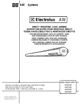
2. Install Bottom Brackets. Pre-install the rst (low-
er) and second (upper) set of bottom brackets.
See FIG. 13.
Important: Structural backing sufcient to withstand
a minimum of 350Lb of normal force must be present at
the mounting locations of all mounting brackets. See
FIG. 13 for the limits of allowed mounting locations
for the rst and second sets of bottom brackets, and
top brackets.
3. Carefully lay the fabric roller tube assembly on
“V” troughs or other well protected surface to pre-
vent fabric damage. Secure arm assemblies to
the respective top castings using 1/4–20 x 1/2”
hex. head machine screws and 1/4” lock wash-
ers. See FIG. 3.
FIG. 3 Top Casting
Lock
Lever
Cotter Pin
Top Mounting
Bracket
Main Arm
¼-20 X ½" Hex
Head Machine
Screw
4. After attaching both arms, rotate the Safe-T-
LockTM lever to the roll down position. Straighten,
remove and discard left cotter pin only. See FIG.
3A.
FIG. 3A
Top Casting
Top Mounting
Bracket
¼-20 X ½" Hex
Head Machine
Screw
Cotter Pin
5. Remove the rafter assemblies from the hardware
and store in a place for re-installation after Step
7. This will reduce the opportunity for the rafters
to become unlatched and scratch the vehicle dur-
ing installation.
6. Prepare the awning rail to accept the awning roll-
er cover. Select the end from which the awning
shall be fed, then widen that end of the rail with
a at screwdriver and le off any sharp edges.
Unwind fabric one revolution before feeding aw-
ning fabric into awning rail. This will allow enough
space between side wall and awning hardware to
feed fabric into awning rail. See FIG. 4.

4
8275000.X09# Series Sunchaser II TC Hardware Installation Instructions
7. Install Awning Assembly. With one person
grasping each support arm, carefully lift the en-
tire assembly upright. Keep the two arm assem-
blies parallel to each other to avoid damage due
to twisting. Carry the awning to the prepared aw-
ning rail end. See FIG. 5. Feed the awning into
the awning rail until the hardware arms reach
the location of the pre-mounted bottom brack-
ets. For safety and ease, it is recommended that
this operation be done while the tent camper is
in its lowest conguration. The hardware arms
must be aligned with the rst (lower) set of bottom
brackets at this time. Snap the hardware feet into
the brackets.
FIG. 4
Before After
Awning Rail
Fabric Roller
Tube Assembly
Arm Assembly
FIG. 5
8. Install Top Brackets. With the hardware arms
secured to the bottom brackets in the desired
location, re-install the rafter assemblies into the
hardware.
Note: The top bracket/ rafter assemblies are independent
of the main support arm assemblies, but may be held to-
gether by snapping the travel locks into the main support
arms.
Place the top mounting brackets directly under-
neath the awning rail (see FIG. 7) ensuring that
they are aligned and centered with the main sup-
port arms. Proper structural backing must be
available in the trailer wall under the awning rail
to anchor the #14 X 3” hex head lag screws (see
Step 2). Slightly pull the main arm away from the
top bracket and rafter. Mark the top bracket posi-
tion and predrill the two 3/16" diameter holes (drill
7/32" diameter if into steel). Install top bracket with
two #14X3" hex head screws. See FIG. 7. Apply
silicone sealant to screw threads and where the
screws enter the coach. Place main support arm
on the top pivot. Repeat for the other side.
Note: Top rafter bracket assembly is independent of the
main support arm assembly.
FIG. 6
FIG. 7 Awning Rail With
Drip Channel
#14 X 3" Hex
Head Screw
Mount Top Bracket
Below Awning Rail
Top Pivot
Rafter
After the top bracket has been mounted, do
not pull the bottom of the arm assembly away
from the side of the vehicle, with the Safe-T-
Lock™ in the roll-up position. Damage to the
torsion lock can occur, which may cause the
torsion to malfunction.
Pull the main support arm away from the top
bracket and rafter. Mark the top bracket position
and predrill the two 3/16” diameter holes (drill
7/32” diameter if into steel). Install top bracket
with two #14 X 3” hex head screws. See FIG.
7. Apply silicone sealant to screw threads and
where the screws enter the coach. Place main
support arm on the top pivot. Repeat for the other
side.
FIG. 8
Patio
Foot
Bottom
Wall
Bracket
Lift And Snap Patio Foot
Into Bottom Wall Bracket
This step is essential for the proper function-
ing all awnings.

5
8275000.X09# Series Sunchaser II TC Hardware Installation Instructions
9. Release Preset Tension.
Check to see if the Safe-T-LockTM lever is in the
roll down position. Remove right cotter pin that is
holding factory preset tension. The cotter pin is
found in the roller tube end cap. See FIG. 10. For
easier removal, twist the roller tube as if unrolling
awning by pulling the bottom of the tube toward
yourself while pulling on cotter pin. Discard pin.
When cotter pins are removed from the tor-
sion, spring tension, will attempt to close
the awning. Keep body clear of hardware
and roller tube.
FIG. 10
Roll Up
Roll
Down
End Cap
Cotter Pin
SAFE-T-LOCK™
Lever Direction
FIG.11
FIG. 12
Squeeze
Travel
Lock
Stop Clip
Travel Lock
While holding the pull strap, move the Safe-T-
Lock™ lever to the roll up position. The awning
should now roll up against the vehicle side. See
FIG. 10.
10. Secure awning to awning rail. Open and close
awning a few times to allow for natural self ad-
justment of awning. Insure the arms are still posi-
tioned directly in front of top brackets. Secure by
installing a #6 x ½” Tek screw on each end. See
FIG. 11. Model 8485000 requires the stop to be
installed in the water dump arm, while awning is
open. See FIG. 10.
11. Operate awning according to the Operational In-
structions in the User's Guide included with the
awning, to check that all parts function properly.
12. Secure awning for travel. For added security and
rattle-free travel, tighten rafter knobs, secure
travel latches and insure torsion lock is in the roll
up position. See FIG. 10 & 12.

6
8275000.X09# Series Sunchaser II TC Hardware Installation Instructions
CENTER OF THE
BOTTOM BRACKET
HOLES
FROM THE CENTER
OF THE AWNING
RAIL HOOP
FROM THE CENTER
OF THE AWNING
RAIL HOOP
ADDITIONAL
WALL BRACKET
CENTER OF THE
BOTTOM BRACKET
HOLES
CENTER OF THE
BOTTOM BRACKET
HOLES
CENTER OF THE
BOTTOM BRACKET
HOLES
26" - 36"
50" MIN
FROM THE CENTER OF
THE AWNING RAIL HOOP
TO CENTER OF THE
MOUNTING HOLES
TOP BRACKET TO BE
MOUNTED UNDER (UP
AGAINST) THE AWNING
RAIL HOOP
CUSTOMER SUPPLIED
SPACER / OFFSET
BRACKET IF NEEDED
88" MAX
2.68"
FIGURE 13: MOUNTING DIMENSIONS
Coach Wall
Coach Wall
Coach
Wall
A
DETAIL A
TRAILER CAP
RETRACTED
TRAILER CAP
EXTENDED
SEE DETAIL A
/