Page is loading ...

Texmate, Inc. Tel. (760) 598-9899 • www.texmate.comFX-BQ-PROCESS manual (d0064) Page 1
• Externaltransmittersorsignalconditionerscanbeeliminated
bydirectlyconnectingthesensortoPlug-inInputSignal
ConditioningModulesthatinclude:
–4-20mA
IP01:
4-20mA Process Loop
IP02:
4-20mA Process Loop with Excitation 24VDC@100mA
–0-10V
ID01:
DC-Volts 2/20/200V with 24V DC Exc
ID05:DC-Volts 2/20/200V with offset and 24V DC Exc
AnalogOutputScalingandCalibration
. 6
CaseDimensions ...............12
ComponentLayout ...............8
ConnectorPinouts ...............7
Connectors .....................7
ControlsandIndicators ...........2
CustomFacePlates&Scales . . . . . 10
GeneralFeatures ................1
GlossaryofProgrammingSymbols&
ModesofOperation ..............2
HingedClearLockablePolyNEMA4X
SplashProofCover ...............12
InputModuleCompatibility.........1
InputModuleComponentGlossary ..9
InstallationGuideline .............7
OnePointQuicksetRescalingand
CalibrationProcedure.............5
OpeningtheCasetoAccessMode
SelectHeader...................4
OrderingInformation ............13
OverviewofDisplayModes,Scaling
Capabilities&OperatingModes.....3
PanelAdapter..................11
PinDescriptions .................7
Specifications ...................1
StandardDisplayModeCalibration
Procedure......................5
TwoPointQuicksetScalingand
Calibration ................... 3,5
• Aredoroptionalgreen101segmentbargraph.
•
Auto-sensing AC/DC power supply. For voltages between
85-265 V AC / 95-300 V DC (PS1)or14-48VAC/10-72VDC(PS2).
•
Optional16Bitisolatedanalogoutputthatcanbeusedtodrive
anexternalprocessdevicesuchasachartrecorder,remote
display,orforretransmissiontoacentralcontrolroom.
Useror
factoryscalableto4to20mA,0to20mAor0to10Vacross
anydesiredspanfrom±onebartothefullscalerange
• Centerzerosetting,headerselectable.
• Provisionforexternalbrightnesssettingswitch(byconnect-
ingtheDIMtotheGNDpinonthebackofthemeter).
• Smartaveraging(tospeedupdisplayresponse).
• OptionalNEMA-4frontcover.
• ULListed
Input Specs: ..............
Dependsonrangeandfunctionselected
A/D Converter: ..........14bitsingleslope
Accuracy: ..................±(0.05%ofreading+1segment)
Temp. Coeff.: .............100ppm/°C(Typical)
Warm up time: ...........2minutes
Conversion Rate: ......10conversionspersecond(Typical)
Bargraph Display: .....
101 segment 4” vertical (std),
horizontal(optn),red (std), green(optn)
Polarity: .....................Selectablecenterzero
Positive Overrange: ..Bargraphdisplayflashes
Negative Overrange:
Firstsegmentofbargraphdisplayflashes
Analog Output: .........Isolated16bituserscalablemAorV
OIC (mA out) ...........
4-20mA@0to500Ωmaxloopresistance
OIV (volts out) ......... 0-10VDC@500Ωorhigherresistance
Power Supply: ...........AC/DCAutosensingwiderangesupply
PS1 (std) ..................
85-265 VAC, 50-400Hz / 95-300 VDC @ 1.5W
PS2 ...............................
14-48VAC,50-400Hz/10-72VDC@1.5W
Operating Temp.: ......0to50°C
Storage Temp: ...........–20°Cto70°C
Relative Humidity: ....95%(noncondensing)
Case Dimensions: ....
9/64 DIN Bezel: 36x144mm(1.42"x5.69")
Depth behind bezel:117.5mm(4.64").
Plus 10mm(0.39”) for Right-angled con-
nector,orplus18.3mm(0.72")forStraight-
thruconnectors.
Weight: .......................9.5oz.,12ozwhenpacked
Index
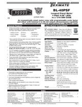
✔ LYNX FAMILY: More than 33 different Plug-in
I-Series Input Signal Conditioners are approved for
Texmate’s Lynx Family of meters.
See www.texmate.com for an up to date listing. LYNX
General Features
Input Module Compatibility Specifications
FX-BQ-PROCESS
Lynx Bargraph Meter
101 Segment in a 9/64 DIN CASE
LYNX FAMILY
A Powerful Smart 4-20mA/0-10V
Process Meter with
Isolated 4-20mA DC or 0-10VDC output

Texmate, Inc. Tel. (760) 598-9899 • www.texmate.comPage2 FX-BQ-PROCESS manual (d0064)
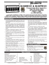
Quickset Programming
ThisbargraphfeaturesTexmate'suniqueQUICKSET
PROGRAMMING. When a front panel button is
pressed and held down, the associated function is
directly changed. The direction of change will be
either up or down, as indicated by the UP and
DOWNindicatorLEDs.AftertheindicatorLEDlights
up there is a 0.5 second delay before any change
occurs. When a button is released and pressed
downagainthedirectionofchangeisreversed.As
there are no menu or sub-menus to navigate, the
programmingandsetupisquickandeasy.
Front Panel Buttons
Zero Button
TheZeroButtonsetsthelowinputsignalscaling.
Span Button
TheSpanButtonsetsthehighinputsignalscal-
ing.
Lo Button
TheLoButtonsetstheanalogoutputlowsetting.
Hi Button
TheHiButtonsetstheanalogoutputhighsetting.
13
24
Z
C
1
Z
C
3
24
Lo
Span
Button
Zero
Button
UPProgram
DirectionIndicator
Hi
DOWNProgram
DirectionIndicator
101
Segment
Bargraph
Controls and IndicatorsControls and Indicators
Controls and IndicatorsGlossary of Programming Symbols and Modes of Operation
Standard or Center Zero Display Mode Select Header
•
Jumperclipsenablesstandarddisplay.
•JumpercliptoenableCenterZerodisplay.
dual bar rvsd
SP1
SP2
SP3
SP4
Horizontal or Reverse Mounting
Meterscanbemountedhorizontallyin
thepanelandforthoseapplicationsthat
requireanoppositegrowthofthebar,the
metercanbeverticallyorhorizontally
mountedupsidedown
Horizontal and Reverse Mounting
withCustomFacePlateInstalled
Toexplainsoftwareprogrammingprocedures,logicdiagrams
areusedtovisuallyassistinfollowingprogrammingsteps.The
followingsymbolsareusedtorepresentthefunctionsanddis-
playsofthemeter:
Input Hi
Input Low
Thisarrowrepresents
thedirectionandlevel
ofaninputsignal
Smallarrowshows
directionthebar-
graphdisplayhas
movedorwillmove.
Shadingindicates
bargraphisONin
thisarea.
When two fingers are shown side by
side,thetwocorrespondingbuttonsmust
bepressedatthesametimetoinitiatean
indicatedfunction.
Zero Span

Texmate, Inc. Tel. (760) 598-9899 • www.texmate.comFX-BQ-PROCESS manual (d0064) Page 3
Input Hi
Input Low
std
Input Hi
Input Low
std Inv
FLB202Q MODE O1
+ Input
- Input
+ Input
- Input
+ Input
- Input
000
biploar center zero
Input Hi Input HiInput Hi
Input Low Input Low
Input Lo
w
center zero
1/21/21/2
Standard Scaling
Standarddisplaymodeselectedand
scaledsobarincreasesasinputsignal
increasesfromLowtoHi.
Halfway Zero Point
Centerpointdisplaymodeselectedand
scaled,sothebarincreasesupwardsor
downwardsfromthecenterpoint,forsig-
nalsthataregreaterorlessthanhalfthe
calibratedfullscalerangerespectively.
Whentheinputisequaltohalfthefull
scalerange,onlythecentersegmentwill
beon.
Inverse Scaling
Standarddisplaymodeselectedand
scaledsothebarincreasesastheinput
signaldecreasesfromHitoLow.
Bipolar Center Zero
Centerpointdisplaymodeselectedand
scaled,sothebarincreasesupwardfrom
zero,forincreasingpositiveinputsand
downwardfromzeroforincreasingnegative
inputs.Whentheinputiszero,onlythecen-
tersegmentwillbeon.
Standard Display Mode
Center Zero Display Mode
Over View of Display Modes, Scaling Capabilities and Operating Modes
13
24
Z
C
1
Z
C
3
24
MeterswithQUICKSET PROGRAMMINGfeatureaunique,easy-to-use,twopointscalingandcalibrationsystem.
Scalingorcalibrationisaccomplishedsimply,byapplyingazeroorlowinputsignalandadjustingthebartothedesiredreading,usingthe
ZERObutton.Ahigherinputsignalisthenapplied,andthebarisadjustedtothedesiredreadingforthatinputvalue,usingtheSPANbutton.
IMPORTANT DETAILS THAT MAKE QUICKSET PROGRAMMING EASY TO USE AND UNDERSTAND
1. Thezeroandspanbuttonsarefunctionallythesame,exceptasfollows:TheZERObuttoncaninitiateascalingwithinputsignalsfrom
zeroto95%offullscale.TheSpanbuttoncaninitiateascalingwithinputsignalsfrom5%offullscaleto105%offullscale.
2. WhenaZeroorSpanbuttonispressed,theUporDownindicatorLEDwillimmediatelylightuptoshowthedirection,inwhichtheBar
willmove,aftera0.5seconddelay.Ifthebuttonisreleasedandpressedagain,theoppositeUporDownindicatorwilllightup,and0.5
secondslatertheBarwillbegintomoveinthatdirectionuntilthebuttonisreleased.Whenthebarisbeingadjustedtozeroorfullscale,
thebarwillautomaticallystopatthezeroorfullscaleposition,andwillnotovershootthesepositions,evenifthebuttoncontinuestobe
pressed.
3. Whilethebarisbeingadjusted,anewoffsetandscalefactoriscontinuouslybeingcalculated.Atthemomentthebuttonisreleased,
andthescalingisaccepted,thecalculationdataismemorizedandimplemented.TheScalingcalculationisbasedonthenewposition
oftheBar,theinputsignalbeingappliedatthatmoment,andthepreviouslymemorizedpositionoftheBarandtheinputsignalthatwas
beingapplied,whentheotherbuttonwaslastreleased.
4. Positiveandnegativesignalsmaybeintegratedintoatwopointscaling.HoweverwheneitheraZEROorSPANbuttonispressedthe
inputsignalbeingapplied,mustbemorethan5%higherorlowerthanthepreviouslymemorizedvalueoftheinputsignal,thatwas
beingappliedwhentheotherbuttonwaslastreleased.Ifnot,thebarwillflash,thescalingwillnotbeaccepted,andthepreviousscaling
willstillberetainedinmemory.
5. Becauseoftherequirement,thatanewscalinginputsignalmustbe5%higherorlowerthanthepreviouslystoredvalue,itcansome-
timesbedifficulttoimplementadesiredscaling,particularlywhenusingacalibratorthatonlyhasfixedoutputvalues.InthiscaseReset
theScalingbypressingtheZEROandSPANbuttonssimultaneouslyfortwoseconds.Bothscalingmemorieswillbeerasedandan
internaldefaultscalefactorwillbeloaded.Thisprovidesadisplayofzerotofullscaleonthebarforaninputofapproximately0to100%
oftherangeselectedontheinputsignalconditioningmodule.AfterResettingtheScalinganewcalibration,usingeitherbutton,canbe
implementedwithnewinputsignalvalues.ItisgoodpracticetoalwaysusetheZerobuttonforlowerinputsignalsandtheSpanbutton
forhigherinputsignals,evenwhenthebardisplayscaleisinversed.
6. Thelargerthedifferencebetweentwopointsusedforcalibration,thebettertheaccuracy.Howeverifthedifferenceistoohigh,and
theoutputfromtheinputsignalconditioningmoduleisgreaterthan+2.1VDC,orlessthan-1.05VDC,thebarwillflashoverrange.The
calibrationwillnotthenbeacceptedand,thepreviousscalingwillstillberetainedinmemory.Inthiscase,eitheralowerinputsignal
mustbeused,orahigherrangeontheinputmoduleshouldbeselectedtorecalibratethemeter.
Note:Mostinputsignalconditionershaveprovisionsforanalogcalibrationandscaling.Ifthemeterʼsscalefactorissettoreadzerowitha
zeroinput(shortedinput),andtoread10Barsfullscalewitha2.000Vinput,anypre-calibratedsignalconditionerwithanoutputthatdoes
notexceed–1Vto+2V,willreadcorrectlyinthemeterwithoutanyfurthercalibration.
Two Point Quickset Scaling and Calibration

Texmate, Inc. Tel. (760) 598-9899 • www.texmate.comPage 4 FX-BQ-PROCESS manual (d0064)
2
1
3
4
Toremovefrontbezellightlylever
theplasticcatchesupandfor-
wardinthesequence
shownbythenum-
bers
Toremoverear
coverplatepress
downlightlytorelease
twoplasticcatches,oneither
sideofthecaseandleverback-
wards.
Controls and IndicatorsOpening the Case to Access Mode Select Header
Meter Exploded view

Texmate, Inc. Tel. (760) 598-9899 • www.texmate.comFX-BQ-PROCESS manual (d0064) Page5
STEP A REVIEW THE INPUT MODULE STATUS
1)Seepages10–15forinformationoninputmodulesthatmaybeusedwiththismeter.
2)Confirmthatthecorrectrangeandinputisselectedontheinputsignalconditioning
module.
Note: Whenundertakinganinitialsetupandprimaryscalingandcalibrationofthemeteritis
besttostartwitharesetofthescaling.
STEP B RESET THE SCALING
1)ApplypowertothemeterandpresstheZEROandSPANbuttonssimultaneouslyfor2
seconds. This erases any previously memorized scalings, and resets the scaling to the
factorydefault,ofapproximatelyzerotofullscale,foraninput,thatis0to100%oftherange
selectedontheinputsignalconditioner.
Standard or Center Zero Display Modemaybeselected,dependingontheOperatingModeselect-
ed.Ifthestandarddisplaymodeisnotalreadyselectedopenthemetercaseasshowingonpage4
andmovethejumperclipsonthedisplaymodeselectheadertotheOFFposition.
StandardDisplaywith
JumperClipsinOFF
position
Standard Display Mode Calibration Procedure
100
0
Zero Span
Lo Hi
ANALOG OUTPUT
Reset the scaling
to the default value
on by pressing
the Zero and
Span buttons
simultaneously
for 2 secs.
1
Z
C
3
24
Note:Tocalibratethebargraphyoumustbeabletoinputtwoinputsignals.Usuallytheminimuminput(LOInput)andthemaximum
input(HIInput)signalsareusedforoptimumaccuracy.Howeverascalingcanbeaccomplishedwithanytwosignalsthatarehigher
orlowerthaneachotherbymorethan5%offullscaleandarenotgreaterthan+2.1VDCorlessthan-1.05VDC.
STEP C SET THE LOW INPUT SIGNAL READING ON THE BAR
1) ApplytheLOinputsignal(4mainthisexample)totheinputpins.
2) UsingtheZERObuttonadjustthebardowntotherequiredposition.
STEP D SET THE HIGH INPUT SIGNAL READING ON THE BAR
1) Applythehighinputsignal(20mAinthisexample)totheinputpins.
UsingtheSPANbuttonadjustthebartotherequiredposition.
Thispositioncouldbehigherorlowerthanthepositionadjustedin
Step2.Thescalingforaninputof4to20mAisnowcomplete.
Apply 4 mA
to the
Input Pins
and adjust
bar display
to the required
position
100
0
Zero Span
Lo Hi
ANALOG OUTPUT
Apply 20 mA
to the
Input Pins
and adjust
bar display
to the required
position
100
0
Zero Span
Lo Hi
ANALOG OUTPUT
Apply 0 mA
to the Input Pins
and adjust
bar display
to the required
position
100
0
Zero Span
Lo Hi
ANALOG OUTPUT
One Point Quickset Rescaling and Calibration Procedure
ONE POINT RECALIBRATION
Asexplainedearlier,theFX-B101Qbargraphiscalibratedusingtwopointcalibration.Onceabargraphiscalibrated,thelowendofthe
rangemaybethenrecalibratedwithoutaffectingthecalibrationofthehighend,andviceversa.
Forexample,takeanFX-B101Qthathasbeencalibratedtoreadzerotofullscaleforaninputof4to20mA.Ifnowthescalinghastobe
changedtoreadzerotofullscaleforaninputof0to20mA,onlythelow(4mA)endneedstoberecalibrated.Thehigh(20mA)endof
thescalingisleftuntouched,andsodoesnotchange.Thefollowingonepointrecalibrationprocedureisusedforthispurpose.
STEP A RECALIBRATE THE LOW INPUT SIGNAL READING ON THE BAR
1) ApplytheLOinputsignal(0mainthisexample)totheinputpins.
Thefirstsegmentwillflash,indicatinganunderrangecondition.
2) UsingtheZERObuttonadjustthebaruptotherequiredposition.
3) TheFX-B101Qhasnowbeenrecalibratedtoreadzerotofullscale
fora0to20mAinput.
Standard Display Mode Calibration Procedure
Standard Display Mode Calibration ProcedureTwo Point Quickset Scaling and Calibration Procedure (continued)

Texmate, Inc. Tel. (760) 598-9899 • www.texmate.comPage 6 FX-BQ-PROCESS manual (d0064)
Forexample:thethreestepstoobtainanAnalogOutputof4mAto20mAforaninputof
0to10Vare:
STEP A RESET THE ANALOG OUTPUT SCALING
1) Press the LO and HI buttons simultaneously and hold them down for 2
seconds.Thiswillresettheanalogoutputscalingtothedefaultvalue.The
defaultanalogoutputscalingisapproximately0to20mA(0to10Vifvoltage
outputoptionisselected)foraninputthatis0to100%oftherangeselect-
edontheinputsignalconditioner.
STEP B CALIBRATE ANALOG OUTPUT FOR LO SIGNAL
1) Applythelowinputsignal(0Vinthisexample)tothemeter.
2) Connectanexternalmultimetertotheanalogoutputpins(Pins17and18).
3) UsingtheLObuttonadjusttheanalogoutputasmeasuredontheexternal
multimetertobetherequiredvalue.(4mAinthisexample).WhentheLO
buttonispressed,theUPorDOWNindicatorLEDshowsthedirectionof
change.ToreversethedirectionofchangereleasetheLObuttonandpress
downagain.Initiallytheoutputchangesveryslowly,butspeedsupasthe
LObuttonremainspresseddown.Theanalogoutputforalowinputcanbe
setinthissteptoanyvalueintherangeof0to20mAor0to10V(ifthe
voltageoutputoptionisselected).
STEP C CALIBRATE ANALOG OUTPUT FOR HI SIGNAL
1) Nextapplythehighinputsignal(10Vinthisexample)tothemeter.
2) UsingtheHIbutton,adjusttheanalogoutputasmeasuredontheexternal
multimetertobetherequiredvalue.(20mAinthisexample).WhentheHI
buttonis pressed the UPor DOWNindicatorLED shows the directionof
change.ReleasetheHIbuttonandpressagaintoreversethedirectionof
change.Initiallytheoutputchanges veryslowly,butspeedsupasthe HI
button continues to remain pressed. This output may be higher or lower
thanthevaluesetinStep2,andmaybeanyvalueintherangeof0to20mA
or0to10V.Thisallowstheeasyreversalofanalogoutputthatisrequiredin
someapplications.
Apply 0 V
to the Input
Signal Pins
+ –
Adjust the Analog
output to 4.00mA
17 18
4.00
100
0
Zero Span
Lo Hi
ANALOG OUTPUT
Apply 10 V
to the Input
Signal Pins
Adjust the Analog
output to 20.00mA
17 18
20.00
+ –
100
0
Zero Span
Lo Hi
ANALOG OUTPUT
Whentheoptionalanalogoutputmoduleisinstalled,anindependentlycalibrated16bitisolated,voltageorcurrentanalogoutputis
available.The analog signal is independently scaled to the input signal and not to the bargraph display.Itisimportanttonote
thattheAnalogOutputiscompletelyindependentlyofthebargraphdisplay.Thismeansforexamplethatthebargraphdisplaymay
bescaledtogofromzerotofullscaleastheinputchangesfrom0to5V,whileatthesametime,theanalogoutputisscaledtogo
from4to20mAastheinputchangesfrom2to3V.Rescalingthebargraphortheanalogoutputwillnotaffectthescalingoftheother.
TocalibratetheAnalogOutputyoumustbeabletoinputtwoinputsignals.Usually
theminimuminput(LOInput)andthemaximum(HIInput)signalsareusedfor
maximumaccuracy.
Analog Output Scaling and Calibration
100
0
Zero Span
Lo Hi
ANALOG OUTPUT
Reset the analog
ouput scaling by
pressing the LO
and HI buttons
simultaneously
for 2 secs.

Texmate, Inc. Tel. (760) 598-9899 • www.texmate.comFX-BQ-PROCESS manual (d0064) Page 7
Straight-thru
Screw Terminal Plug
Part Numbers:
93-PLUG2P-DS....2 pins
93-PLUG3P-DS....3 pins
93-PLUG4P-DS....4 pins
Pin SocketPin Socket
Pin SocketPin Socket
Right-angled
Screw Terminal Plug
Part Numbers:
93-PLUG2P-DR.....2 pins
93-PLUG3P-DR.....3 pins
93-PLUG4P-DR.....4 pins
Input Power
Screw Terminal Plug
Part Number:
93-PLUG2P-DP
Straight-thru Input Power
Screw Terminal Plug
Part Number:
93-PLUG2P-SP
93-PLUG5P-DR....5 pins
93-PLUG6P-DR....6 pins
WARNING
AC and DC input signals and power
supply voltages can be hazardous. Do
Not connect live wires to terminal
blocks, and do not insert, remove or
handle terminal blocks with live wires
connected.
Standardplug-inscrewterminalblocksprovidedbyTexmate:
Connectors
!
WARNING
AC and DC power supply voltages are hazardous. Make sure
the power supply is isolated before connecting to the meter.
LOCK
GND
DIM
17 18 19 20 21 23 24
1-6
See Lynx Family Input
Signal Conditioning Moduls
Analog
Output +
Analog
Output – AC
Neutral AC
Line
– DC + DC
or
Thismeterusesplug-intypescrewterminalconnectorsforallinput
and output connections. The power supply connections (pins 23
and 24) have a unique plug and socket outline to prevent cross
connection. The main board uses standard right-angled connec-
tors.Replacement2-,3-,and4-pinplugconnectorsareavailable.
Input Signal – Pins 1 to 6
Pins1to6arereservedfortheinputsignalconditioner.
Seethedatasheetfortheselectedinputsignalconditioner.
Rear Panel Switches – Pins 17 to 21
Pin 17 ANALOG OUTPUT (+).mA(0to20mA/4to20mA)
orV(0to10V)outputisheaderselectable.
Pin 18 ANALOG OUTPUT (–).mA(0to20mA/4to
20mA)orV(0to10V)outputisheaderselectable.
Pin 19 Programming LOCK.ByconnectingtheLOCKpin
totheCOMMONpin,themeter'sprogrammed
parameterscanbeviewedbutnotchanged.
Pin 20 COMMON.ToactivatetheLOCKorDIMfunctions
fromtherearofthemeter,therespectivepinshave
tobeconnectedtotheCOMMONpin.Thispinis
connectedtotheinternalpowersupplyground.
Pin 21 DIM.Byconnectingthedisplaydim(DIM)pinto
theCOMMONpin,thedisplaybrightnesssetting
ishalved.
Pins 23 and 24 – AC/DC Power Input
Auto-sensingAC/DCpowersupply.Forvoltagesbetween
85-265VAC,50~400Hz/95-300VDC(PS1)oroptional
14-48VAC50~400Hz/10-72VDC1.5Wnominal.(PS2).
Pin 23 AC Neutral / –DC.Neutralpowersupplyline.
Pin 24 AC line / +DC.Livepowersupplyline.
Controls and IndicatorsConnector Pinouts
Pin Descriptions Installation Guidelines
Installation
1.Installandwiremeterperlocalapplicablecodes/reg-
ulations,theparticularapplication,andgoodinstallation
practices.
2.Installmeterinalocationthatdoesnotexceedthe
maximum operating temperature and that provides
goodaircirculation.
3. Separate input/output leads from power lines to
protect the meter from external noise. Input/output
leads should be routed as far away as possible from
contactors,controlrelays,transformersandothernoisy
components.Shieldingcablesforinput/outputleadsis
recommended with shield connection to earth ground
nearthemeterpreferred.
4.Acircuitbreakerordisconnectswitchis requiredto
disconnect power to the meter. The breaker/switch
shouldbeincloseproximitytothemeterandmarkedas
thedisconnectingdeviceforthemeterormetercircuit.
Thecircuitbreakerorwallswitchmustberatedforthe
appliedvoltage(e.g.,120VACor240VAC)andcurrent
appropriate for the electrical application (e.g., 15A or
20A).
5.SeeCase Dimensions section for panel
cutoutinformation.
6.SeeConnector Pinouts sectionforwiring.
7.Use28-12AWG wiring, minimum90˚C
(HH)temperaturerating.Stripwireapprox-
imately0.3in.(7-8mm).
8.Recommendedtorqueonallterminalplugscrewsis
4.5lb-in(0.51N-m).
!

Texmate, Inc. Tel. (760) 598-9899 • www.texmate.comPage 8 FX-BQ-PROCESS manual (d0064)
Component Layout
MAIN BOARD
Low Voltage
Hi Voltage
4-20mA INPUT MODULE
0-10V INPUT MODULE
4 to 20mA Process Loop Measurement
Order IP02, if you require the loop
excitation voltage (24VDC@100mA)
to be supplied by the meter.
24V
External
Loop Supply
Common
ZERO
SPAN
Oset PROCESS 4/20 mA
0
+
_
Other devices can be
added to the loop.
Direction
Of
Current
<Decrease Zero Increase >
<Decrease Span Increase >
Range
HI
LO
OFF
ON
24V EXC
Fully User Scalable
PIN 2
PIN 1
PIN 3
+_
Exc.On/Off
Header
SPANPot
HI/LOW
SPANRANGE
Header
ZEROPot
ZEROADJUSTHeader
SPANADJUST
Header
ZEROOFFSET
RANGEHeader
<DecreaseIncrease>
<DecreaseIncrease>
Lo
Hi
OFF
ON -
0
+
InputRange
Header
Exc.On/Off
Header
Exc.On/Off
Header
SpanAdj.
Header
SpanAdj.
Header
ZeroOffset
RangeHeader
SpanPot
SpanPot
(ID05)
(ID01)
(IP01/IP02)
ZeroOffsetPot
InputRange
Header
ID01:
DC Volts, 2/20/200V/Custom w/24V DC Exc
Custom
200V
20V
2V
ON
OFF
24V Exc
24V
Exc
< Decrease Span Increase >
SPAN
DC VOLTS
PIN 1
PIN 2
PIN 3
Custom
200V
20V
2V
ON
OFF
24V Exc
24V
Exc
< Decrease Span Increase >
SPAN
ZERO
DC VOLTS
PIN 1
PIN 2
PIN 3
ID05: DC Volts 2/20/200/Custom V DC with Offset
and 24V Exc.
0
+
_
Offset

Texmate, Inc. Tel. (760) 598-9899 • www.texmate.comFX-BQ-PROCESS manual (d0064) Page 9
Input Module Component Glossary
LO RANGE HI RANGE
10%SPAN Pot %10% 10% 10% 10%
10%Signal Span %20% 30% 40% 50%
1
SPAN Adjust
Header position
Span Adjust Header Span Adjust Header
Span Range Header
2 3 4 5
10% 10% 10% 10% 10%
60% 70% 80% 90% 100%
1 2 3 4 5
< Decrease Span Increase >
12 345
< Decrease Span Increase >
12 345
Equivalent
Circuit
Acts like a
150 Tu rn
Potentiometer Low Range High Range
Input LO Input HI
HI
LO
SPAN RANGE Header
Whenthisheaderisprovideditworksinconjunc-
tionwiththeSPANADJUSTHeaderbysplittingits
adjustmentrangeintoaHiandaLorange.This
hastheeffectofdividingtheadjustmentrangeof
the SPAN pot into ten equal 10% steps across
100%oftheinputSignalSpan.
Range
HI
LO
HI
LO
SPAN
Tu rn Clockwise to
Increase Reading
To the
Right Rear
SPAN Potentiometer (Pot)
Ifprovided,the15turnSPANpotisalwaysonthe
rightside(asviewedfromtherearofthemeter).
Typical adjustment is 20% of the input signal
range.
20%SPAN Pot %20% 20% 20% 20%
20%Signal Span %40% 60% 80% 100%
1
SPAN Adjust
Header position 2 3 4 5
< Decrease Span Increase >
12 345
Acts like 75 Tu rn 1 Mega ohm Potentiometer
Input LO
Input
HI
Equivalent
Circuit
SPAN ADJUST Header
This unique five-position header expands the adjust-
mentrangeoftheSPANpotintofiveequal20%steps,
across100%oftheinputSignalSpan.AnyinputSignal
Spancanthenbepreciselyscaleddowntoprovideany
requiredDigitalDisplayspanfrom1999countsto001
(onecount).
ZERO
Tu
rn Clockwise to
Increase Reading
To the
Left Rear
15 Tu rn Potentiometer
≈ + 100 Counts≈ – 100 Counts
–0+
ZERO Potentiometer (Pot)
If provided, the ZERO pot is always to the left
oftheSPANpot(asviewedfromtherearofthe
meter).Typicallyitenablestheinputsignaltobe
offset±5%offullscale(-100to+100counts).
ZERO ADJUST Header
Whenthisheaderisprovided,itworksinconjunc-
tion with the ZERO OFFSET RANGE Header,
andexpandstheZEROpot’soffsetcapabilityinto
five equal negative steps or five equal positive
steps. This enables virtually any degree of input
signaloffsetrequiredtodisplayanydesiredengi-
neeringunitofmeasure.
ZERO OFFSET RANGE Header
When provided, this three position header
increasestheZEROpot’scapabilitytooffsetthe
inputsignal, to ±25% of the digital displayspan.
ForexampleaNegativeoffsetenablesa1to5V
inputtodisplay0tofullscale.Theusercanselect
negativeoffset,positiveoffset,ornooffset(ZERO
potdisabledfortwostepnon-interactivespanand
offsetcalibration).
Offset
0
–
+
0
–
+
24V DC Output Header
On some modules this header enables a 24V
DC25mA(max)Excitation/Auxiliaryoutputtobe
connectedtoPin2.
ON
OFF
OFF
ON
24V EXC
Zero Offset Range Header
0+–
–20%ZERO Pot %–20% –20% –20% –20%
No
Offset
NEGATIVE OFFSET POSITIVE OFFSET
–1200 or more countsOffset Range
+20% +20% +20% +20% +20%
+1200 or more counts
5
ZERO Adjust
Header position 4 3 2 1 1 2 3 4 5
75 Tu rn Potentiometer
–0
Equivalent
Circuit
< Increase Zero Decrease >
54 321
< Decrease Zero Increase >
12 345
75 Tu rn Potentiometer
+0
Zero Pot
Disabled
Zero Offset Range Header
0+–
No
Offset
NEGATIVE OFFSET
Decreases Digital Reading
POSITIVE OFFSET
Increases Digital Reading
15 Tu rn Potentiometer
–0
Equivalent
Circuit
15 Tu rn Potentiometer
+0
Zero Pot
Disabled
⊕ – 500 CountsOffset Range
– 100% of Offset
ZERO Pot%
⊕ + 500 Counts
+ 100% of Offset

Texmate, Inc. Tel. (760) 598-9899 • www.texmate.comPage10 FX-BQ-PROCESS manual (d0064)
10x5
50
8
9
10
0
1
2
3
4
5
6
7
6x5
30
0
10
20
30
40
50
60
7.5x5
37.5
0
10
20
30
40
50
75
60
70
8x5
40
0
10
20
30
40
50
80
60
70
9x5
45
0
10
20
30
40
50
90
80
60
70
6x2x2
24
8
12
10
0
2
4
6
4x5x2
40
20
0
5
10
15
5x5x2
50
25
20
0
5
10
15
6x5
30
30
25
20
0
5
10
15
8x5
40
40
30
35
25
20
0
5
10
15
9x5
45
45
40
30
35
25
20
0
5
10
15
10x5
50
50
45
40
30
35
25
20
0
5
10
15
5x3x2
30
12
15
0
3
6
9
1
10
100
1000
1.5
15
150
1500
2
20
200
2000
2.5
25
250
2500
3
30
300
3000
4
40
400
4000
4.5
45
450
4500
5
50
500
5000
6
60
600
6000
7.5
75
750
7500
8
80
800
8000
9
90
900
9000
1.2
12
120
1200
Div.
136 mm (5.35")
28 mm
(1.1")
Face plate scales
and numbers are shown
close to their actual size.
Some horizontal scales
only have numbers on each
second major division.
Zero Lo
Hi
Span
Analog
Output
0
Zero
Lo
Analog Output
Hi
Span
0
Custom Face Plates and Scales
Texmate Produces Thousands of Custom
OEM Face Plates
Have Texmate Design and Build a Custom
FacePlatetoSuityourNextproject!
• Custom face plates have a non-recurring
artwork charge. A serial number is then
assignedtoeachartwork,tofacilitatere-ordering.Weprefer
custom logos and special artwork to be supplied in an
IllustratororPhotoshopfileformat.
•SmallRunorOne-Offcustomfaceplatesincuraninstallation
charge, and are generally printed on a special plastic film,
whichisthenlaminatedtocustomfaceplateblanksasrequired.
• Large Run (300 pieces min): custom face plates are produc-
tion silk screened, issued a part number, and held in stock for
free installation as required by customer orders.
• OEMs may also order Custom Meter Labels, Box Labels
Custom Data Sheets and Instruction Manuals.
Part Number Description List
Small Run Custom Face plates for Bargraphs
ART-NRC-DES ....Small run NRC custom faceplate design............$100
ART-NRC-LOGO...
Small
run
NRC custom faceplate design with Co.Logo
..$170
ART-FS1 .........Small run custom Faceplate - 1 color ...............$40
ART-FS2 .........Small run custom Faceplate - 2 color ...............$45
ART-FS3 .........Small run custom Faceplate - 3 color ...............$54
ART-FS4 .........Small run custom Faceplate - 4 color ...............$60
ART-FS5 .........Small run custom Faceplate - 5 color ...............$65
Specify artwork serial number when ordering face plate installation.
ie: AFB-XXXXX
Large Run Custom Face plates for Bargraphs
ART-NRC-FILM....Large run NRC custom faceplate design & films.....$1176
ART-FPMAINT ....Inventory management fee for 2 years .............$200
ART-FL1 .........Large run 300pcs custom faceplate - 1 color ........$900
ART-FL2 .........Large run 300pcs custom faceplate - 2 color ........$980
ART-FL3 .........Large run 300pcs custom faceplate - 3 color .......$1060
ART-FL4 .........Large run 300pcs custom faceplate - 4 color .......$1140
ART-FL5 .........Large run 300pcs custom faceplate - 5 color .......$1220
When ordering Large Run Face plates to be installed specify the custom part
number issued for each different artwork. ie: 77-FLXXXXX

Texmate, Inc. Tel. (760) 598-9899 • www.texmate.comFX-BQ-PROCESS manual (d0064) Page 11
Theadaptersnapsonthe36x144mm
(1.42”x5.69”)caseandenablessingleunit
orstackmountinginanexisting6”edgewise
pointermetercut-out.
Twobezeltrimstripsareprovid-
edwitheachadaptertofinishoff
the edge of each individually
mounted meter or the edge of
eachstackmountedarray.
TexmateʼspaneladapterenablesmodernDINmeterstofitinexistingcutouts
individuallyorstackedwhenreplacingold6”edgewisemechanicalpointermeters.
Fits existing cut-outs for 6”
(150 mm) edgewise switchboard
pointer meters from:
•Crompton
•G.E.
•Westinghouse
•Yokogawa
•andmostothers
Width:43.7mmto48mm
(1.72”)to(1.89”)
Height:143.4mmto149mm
(5.62”)to(5.88”)
Fits 6” Edgewise Pointer Meter Cut-Outs
Panel Adapter
When extra panel
mounting tightness
is required, order the
optional screw mount clip.
P/N.(OPMTLCLIP)
Adapteruseswodejaw
moutingslideclips.
P/N(75-DMC14436B)

Texmate, Inc. Tel. (760) 598-9899 • www.texmate.comPage12 FX-BQ-PROCESS manual (d0064)
Clear Lockable NEMA 4X
Splash Proof Lens Cover
P/N.(OP-N4/144X36 )
133.5mm
(5.27")
Mosaic
Fitting
9/64 DIN
cutout
spacer
To open rear cover,
use a small flat
blade screw driver.
Press down lightly
to release catch and
leaver outwards.
SIDE VIEW
137.7mm
(5.42")
9/64 DIN
cutout
spacer 142.3mm
(5.62")
Max. panel thickness
43mm
(1.7")
For additional strength,
extra Mounting Slide Clips
can be ordered and doubled up
one behind the other.
P/N. (75-DMC144X36)
4.5mm
(0.18")
Metal Surround Case
P/N.(OP-MTL144X36) is pre-installed
at the factory and cannot be removed
without damage to the case.
Two bezel Trim
Strips are supplied with
each Panel Adaptor
Panel Adaptor to fit existing 6" Edgewise
Pointer Meter Cut-Outs P/N.(OP-PA/144x36)
Adaptor uses wide jaw mounting slide
clips.P/N.(75DMC14436B)
When extra panel
mounting tightness is
required,
order the optional
screw mount
clip.
P/N.(OPMTLCLIP)
FRONT VIEW
144mm
(5.69")
36mm
(1.42") 4mm
(0.16")
typical
9/64 DIN
36x144 mm
100
0
10
30
50
70
90
20
40
60
80
4
3
2
1
P
SP
PANEL CUTOUT
138mm
(5.45")
33mm
(1.3")
Snug
Fitting
Loose
Fitting
8 places
7.5mm(0.3")
3.5mm(0.14")
4 places
4 places
32.2 mm
(1.27")
Mosaic
Fitting
133mm
(5.25")
135.2mm
(5.34")
3mm(0.12")
9/64 DIN
cutout
spacer
Case will mount in standard DIN cutouts
Various
bezel colors
are available.
Black is
standard.
The Metal Surround
case uses Metal
Screw Mount Clips
and has a max.
panel thickness
mounting of
7mm(0.28")
TOP VIEW
5mm
(0.20") 117.5mm
(4.64")
18.3mm (0.72")
Straight-thru
Connector
31mm
(1.22")
34mm
(1.34")
Mosaic Fitting
Right-angled
Connector
6mm
(0.24")
10mm
(0.39")
26.5mm (1.05")
Push-On Connector
for FI series IO board
The adapter snaps on
the 36x144 mm
(1.42"x5.69") case and
enables single unit or
stack mounting in an
existing 6" edgewise
pointer meter cut-out.
100
0
25
50
75
100
0
25
50
75
SP1 SP2 SP3 SP4
Zero Span Zero Span
Panel adaptor plates are
available to retrofit most
existing panel cutouts.
31mm
(1.22")
These dimensions are
increased by 2mm (0.08") when
the metal surround case is installed.
For extra strength in portable applications,
the 8 DIN spacers should be snipped
off and the Mosaic fitting cutout used.
Controls and IndicatorsCase Dimensions
This rugged, impact resistant, clear lens cover is
designedtobedustandwaterprooftoNEMA4and
IP65standards.Thelenscoverconsistsofabase
and cover with a cam hinge and key-lock locking
device.
AnO-ring,orneoprenegasketformsasealbetween
thebaseandthepanel.Whenopened,acamhinge
preventsthecoverfromclosinguntilpushedclosed.
Thecoverhasataperedrecessthat,whenclosed,
forms a capillary seal with a tapered ridge on the
base. A capillary seal is created when capillary
actioncausesasmallamountofwatertobedrawn
inbetweenthetwosurfacesproducingawatertight
filmaroundthesealingarea.
For those applications, such as food processing,
wherefluidresiduesareunacceptable,applyalight
coatingofclearsiliconegrease,orotherapproved
sealanttothematinggrovetopreventanyingress
ofliquid andenable thecover towithstand steam
cleaning.
Turningthekey-locktightensthecovertothebase,
ensuring seal integrity. A safety catch keeps the
cover closed even when the key is turned to the
openpositionandremoved.Thekeyholecanalso
be used to attach a safety seal clip, preventing
unauthorizedopening.
Hinged Clear Lockable Polycarbonate NEMA 4X Splash Proof Cover
9/64 DIN
36x144 mm (1.42"x5.69")
P/N: OP-N4/144X36
Base
O-ring
Gasket
Cover
Removable
Key-lock
Panel
Safety
Catch

Texmate, Inc. Tel. (760) 598-9899 • www.texmate.comFX-BQ-PROCESS manual (d0064) Page 13
BASE MODEL #
DISPLAY POWER SUPPLY INPUT MODULES
OA____
OPTIONS / ACCESSORIES
ANALOG OUTPUT
BASE MODEL #
DISPLAY POWER SUPPLY INPUT MODULES
OA____
OPTIONS / ACCESSORIES
BASE MODEL #
DISPLAY POWER SUPPLY INPUT MODULES
OA____
OPTIONS / ACCESSORIES
RELAY OUTPUT
FX-BQ-PROCESS
Add to the basic model number the order code suffix for each standard option required. The last suffix is to
indicate how many different special options and or accessories that you may require to be included with this product.
Ordering Example: FX-B101Q-PROCESS-VR-PS1-IA01-OA2, the 2 OA’s are, ZR and a OP-PA/144X36
Ordering Information
BASE MODEL NUMBER
FX-BQ-PROCESS
144x36mm, Lynx, 101 Seg Bargraph Process input .....$170
Standard Options for this Model Number
Order Code Suffix Description List
DISPLAY
VR .... 101 Segment Red LED Bargraph, Vertical
....................$0
HR....101 Segment Red LED Bargraph, Horizontal ...............$5
VG....101 Segment Green LED Bargraph, Vertical................15
HG ...101 Segment Green LED Bargraph, Horizontal .............$20
POWER SUPPLY
PS1 ... 85-265VAC/95-300VDC ................................. N/
C
PS2 ...15-48VAC/10-72VDC................................. $35
INPUT MODULES
(Partial List. See www.texmate.com)
Unless otherwise specified Texmate will ship all modules precalibrated with facto-
ry preselected ranges and/or scalings as shown in
BOLD
type.
IP01.. ProcessLoop,4-20mA(0-100.00)......................$42
IP02.. ProcessLoop,4-20mA(0-100.00)w/24VDCExc ...........$53
ID01 . DC-Volts, 2/20/200V/Customw/24VDCExc ............$32
ID05 . DC-Volts2/20/200/CustomVDCw/Offsetand24VExc. ...$53
ANALOG OUTPUT
OIC ...Isolated 16 Bit Current Output, 4-20mA...................$40
OIV ...Isolated 16 Bit Voltage Output, 0-10VDC ..................$40
Special Options and Accessories
Part Number Description List
SPECIAL OPTIONS
(Specify Inputs or Outputs & Req. Reading
)
ZR
..............
Calibrated Range Change to another Standard Range
. . $8
ZS-AOB...........Custom scaling of analog output for Q-series bargraphs.........$15
ACCESSORIES
(Specify Serial # for Custom Artwork Installation)
75-DMC14436B ...Side Slide Brackets-Wide opening (2 pc) ............$2.50
75-DMC144X36 ...Side Slide Brackets-stand. (2 pc) - extra set ..........$2.50
93-PLUG2P-DP....Extra Screw Terminal Conn., 2 Pin Power Plug ........$2.50
93-PLUG2P-DR ...Extra Screw Terminal Conn., 2 Pin Plug .............$2.50
93-PLUG3P-DR ...Extra Screw Terminal Conn., 3 Pin Plug .............$4
93-PLUG4P-DR ...Extra Screw Terminal Conn., 4 Pin Plug .............$5
93-PLUG5P-DR ...Extra Screw Terminal Conn., 5 Pin Plug .............$6
DN.CAS144X36 ...Complete 144x36mm Case with Bezel ..............$25
75-DBZ144X36 ....Black Bezel for 144x36mm Case ..................$2.50
OP-MTL144x36
...
Metal Surround Case, includes screw mounting clips
...
$25
OP-MTLCLIP
...... Screw Mounting Clips (2 pc) - to screw tighten slide brackets $8
OP-N4/144X36
.... 144x36mm clear lockable front cover-NEMA 4X, splash proof. $30
OP-PA/144X36
....
Panel Adapter for 144x36mm from 6 inch cutout
...... $10
For Custom Face Plates and Scales see page 10.
Prices subject to change without notice.
WARRANTY
Texmatewarrantsthatitsproductsarefreefromdefectsinmaterialandworkmanshipunder
normaluseandserviceforaperiodofoneyearfromdateofshipment.Texmate’sobligations
underthiswarrantyarelimitedtoreplacementorrepair,atitsoption,atitsfactory,ofanyofthe
products which shall, within the applicable period after shipment, be returned to Texmate’s
facility, transportation charges pre-paid, and which are, after examination, disclosed to the
satisfactionofTexmateto be thusdefective.The warranty shallnot apply to any equipment
whichshallhavebeenrepairedoraltered,exceptbyTexmate,orwhichshallhavebeensub-
jectedtomisuse,negligence,oraccident.InnocaseshallTexmate’sliabilityexceedtheoriginal
purchaseprice.Theaforementionedprovisionsdo notextendtheoriginalwarrantyperiod of
anyproductwhichhasbeeneitherrepairedorreplacedbyTexmate.
USER’S RESPONSIBILITY
Wearepleasedtooffersuggestionsontheuseofourvariousproductseitherbywayofprinted
matterorthroughdirectcontactwithoursales/applicationengineeringstaff.However,sincewe
have no control over the use of our products once they are shipped, NO WARRANTY
WHETHEROF MERCHANTABILITY, FITNESS FORPURPOSE, OR OTHERWISEismade
beyondtherepair,replacement,orrefundofpurchasepriceatthesolediscretionofTexmate.
UsersshalldeterminethesuitabilityoftheproDXctfortheintendedapplicationbeforeusing,
andtheusersassumeallriskandliabilitywhatsoeverinconnectiontherewith,regardlessof
any of our suggestions or statements as to application or construction. In no event shall
Texmate’sliability,inlaworotherwise,beinexcessofthepurchasepriceoftheproduct.
Texmatecannotassumeresponsibilityforanycircuitrydescribed.Nocircuitpatentorsoftware
licensesareimplied.Texmatereservestherighttochangecircuitry,operatingsoftware,speci-
fications,andpriceswithoutnoticeatanytime.
1934KelloggAve.,Carlsbad,CA92008
Tel: 1-760-598-9899 • USA 1-800-839-6283 • 1-800-TEXMATE
Fax: 1-760-598-9828 • Email: [email protected] • Web: www.texmate.com
FX-BQ-PROCESS Technical Manual Copyright © 2019 Texmate Inc. All rights
reserved. Published by: Texmate Inc. USA. Information in this Technical Manual
is subject to change without notice due to correction or enhancement. The
information described in this manual is proprietary to Texmate, Inc. and may
not be copied, reproduced or transmitted, in whole or in part, in connection with
the design, manufacture, or sale of apparatus, device or private label product
without the express written consent of Texmate, Inc.
/