Page is loading ...

79-15022-00 REV. E2 www.srsmith.com Page 1 of 4
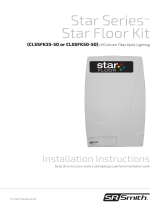
10.75”
MAXIMUM SOIL HEIGHT:
DO NOT ALLOW FILL TO
EXCEED THIS LEVEL!
12”
9.75”10.5”
22.75”
4”
4”
13”
11.5”
6004 SERIES
WARNING: DO NOT INSTALL
WITHIN 1.5M (5 FT.) OF A
POOL, SPA, OR HOT TUB.
ADVERTISSEMENT: NE PAS
INSTALLER A MOINS DE 1,5M
D’UNE PISCINE OU D’UNE
CUVE DE RELAXATION.
INSTALLATION MANUAL
ELECTRICAL
Voltage required: 120VAC 60Hz
Power consumption: 200 Watts max
Start current load: 4.4 amps
Current usage: 1.8 amps
LAMP
Type: Metal-Halide, proprietary design
Lamp life: 6000 hrs average
Cool down restrike period: 3 minutes
Replacement p/n: Y20-6000
SPECIFICATIONS
CONSTRUCTION
Case: High Impact Polycarbonate
Ventilation: 110 cu ft/min air volume
Acoustic rating: 50dB(A)
Weight: 20 lbs.

79-15022-00 REV. E2 www.srsmith.com Page 2 of 4
ELECTRICAL CONNECTIONS
6004 SERIES
120v 60Hz ONLY
MANUAL CONTROL
COLOR WHEEL
ON
POWER
ON
COLOR WHEEL
OFF
POWER
OFF
EXTERNAL AUTO CONTROL
COLOR WHEEL POWER
OPTIONAL RM6000 CONTROL
COLOR WHEEL POWER
TOGGLE SWITCH POSITIONS
EXTERNAL AUTO CONTROL HOOK-UP FOR COLOR WHEEL
For WPC, Jandy Aqualink, Compool, etc.
Run a 120V hot wire to the illuminator from a second relay in
the control’s sub panel for the color wheel control. Connect
this wire to the folded brown wire with fuse. Place the Color
Wheel toggle switch in the bottom position.
EXTERNAL
COLOR WHEEL
CONTROL
(BROWN)
OPTIONAL RM6000 CONTROL
COLOR WHEEL POWER
TOGGLE SWITCH POSITIONS
OPTIONAL RM6000 WIRELESS REMOTE
This RM6000 Automatic Operating System package is
specifically designed for the Lifetime Illuminator™ fiber
optic illuminator and should not be modified or
adapted in any way. This is an electric component
and should only be installed by a qualified technician.
Please follow the instructions carefully. RANGE IS
APPROXIMATELY 75 FEET DEPENDING ON
CONDITIONS.
Light On Light Off
Color Wheel Start Color Wheel Stop

79-15022-00 REV. E2 www.srsmith.com Page 3 of 4
REFER TO THE DIAGRAM ON THE FRONT OF THIS MANUAL FOR THE FOLLOWING
PROCEDURES
1) SEE OUR GENERAL INSTALLATION MANUAL FOR FIBER AND CONDUIT INSTALLATION
IN THE POOL. THIS MANUAL COVERS THE 6000 SERIES ILLUMINATOR INSTALLATION
ONLY.
2) CUT THE FIBER CONDUITS SO THEY WILL ENTER THE INSTALLATION BASE
APPROXIMATELY HALFWAY. CUT THE ELECTRICAL CONDUIT SO IT WILL PROTRUDE
PAST THE CONDUIT HOLE 1” OR LESS (FIG A.). PULL ALL FIBER OPTIC CABLES AT
LEAST 12” THROUGH THE TOP OF THE INSTALLATION BASE.
3) FOLLOW THE PORT ASSEMBLY PROCEDURES ON THE BACK OF THIS MANUAL.
4) PLACE THE CHASSIS ON THE INSTALLATION BASE. SECURE THE ILLUMINATOR WITH
THE TWO SCREWS SUPPLIED. SNAP THE PORT INTO THE CLIP ON THE CHASSIS. MAKE
MAKE SURE IT SEATS FIRMLY INTO THE CLIP (FIG B.).
5) MAKE THE ELECTRIC CONNECTIONS AS SHOWN ON THE PREVIOUS PAGE. MAKE SURE
NO WIRES INTERFERE WITH THE COOLING FAN OR COLOR WHEEL.
6) a) IF INSTALLING IN THE GROUND:
BACKFILL HALFWAY UP THE INSTALLATION BASE. ALLOW AMPLE HEIGHT FOR TOP
SOIL AND LANDSCAPING. DO NOT ALLOW THE VENTS ON THE BOTTOM OF THE
ILLUMINATOR TO BE BLOCKED. THIS WILL CAUSE THE ILLUMINATOR TO OVERHEAT
AND SHUT OFF.
b) IF SURFACE MOUNTING:
USE PROPER SECURING SCREWS FOR THE SURFACE TYPE YOU ARE ATTACHING TO,
USING THE 2 HOLES PROVIDED ON THE BASE. EXAMPLE: FOR CONCRETE, USE
PROPER CONCRETE SCREWS. FOR WOOD SURFACE, USE PROPER WOOD SCREWS.
FIG A.
APPROVED CONDUITS FOR USE WITH FIBER
OPTIC CABLES
• White PVC conduit/pipe SCH 40 or SCH 80
• Gray PVC conduit/pipe SCH 40 or SCH 80
• Flexible PVC pipe
• Black poly pipe
• Any other suitable conduit
FIBER CONDUIT HOLE
AT LEAST 12” OF FIBER
MUST BE PROTRUDING PAST HOLE
ELECTRICAL CONDUIT HOLE
ELECTRIC CONDUIT SHOULD
PROTRUDE 1” OR LESS
USE SWEEP ELLS OR HEAT BEND
FOR GENTLE RADIUS
FIG B.
INSTALLATION GUIDELINES

79-15022-00 REV. E2 www.srsmith.com Page 4 of 4
SMALL
UP TO 100 FIBERS
MEDIUM LARGE
101 TO 200 201 TO 300
XTRA LARGE
301 TO 400 401 TO 450
MAXIMUM
TIP SIZES
PORT ASSEMBLY/FIBER TERMINATION
A) Insure that the total fiber count of
all fiber tubings is 450 or less. If
you have more than 450 individual
fibers, you will need a second
illuminator. The maximum
capacity of the 6004 series port is
450 fibers (optional CCS-600 for
expanding port to 600 fibers sold
separately).
B) Insert the proper size tip into the
port and twist with pliers to lock
(fig. 1).
C) Strip back all fiber casings no less
than 4 inches (fig. 2). Take care
not to nick the fibers.
D) Insert the bare fibers into the port
so ALL fibers protrude past the
port tip (fig. 3). Tighten the port
compression nut down on the
fiber casing (fig. 4).
E) IMPORTANT: If the port tip is not
completely full, insert scrap
individual fibers into the tip until it
is completely full (fig. 5). This will
keep the lit fibers perpendicular to
the lamp, and prevent the fibers
from overheating.
F) Plug in the hot knife (p/n FS-118)
and allow it to heat up. Apply firm
downward pressure on the fibers,
with the blade touching the port
tip at a slight angle (fig. 6.) Do not
saw at the fibers. Allow the heat
of the knife to slowly trim the
fibers. Ease the pressure as the
knife almost completes the cut.
Unplug the hot knife and place it
in a safe place to cool.
/