Page is loading ...

Installation / Service Instructions
For the latest documentation, visit www.escea.com
AF / FS
-Series
630343_5
Gas Fireplace

Important:
The appliance shall be installed in accordance with;
• This installation instruction booklet
• Local gas tting regulations
• Municipal building codes
• Electrical wiring regulations
• Any other relevant statutory regulations.
• AS/NZS 5601:2013 Gas Installations
NOTE: NOT INTENDED FOR FIREPLACE INSERT
WARNING:
This appliance must be installed by a qualied person.
Do not modify this appliance.
This appliance is not intended for use by young children or inrm persons unless they have
been adequately supervised by a responsible person to ensure that they can use the appli-
ance safely.
Young children should be supervised to ensure that they do not play with the appliance.
Failure to follow these instructions could cause a malfunction of the heater, which could result
in death, serious bodily injury, and/or property damage. Failure to follow these instructions
may also void your re insurance and/or warranty.
Who can install this product:
Installation must be carried out by a registered installer who, on completion of the
installation, must issue a:
AUS: Certicate of Compliance
NZ: Certicates that comply with the latest legislation
in accordance with national and/or local codes. If these are not issued then the Escea
warranty may be void.
Warranty Repair and Annual Servicing:
Warranty repair work must be carried out by a recognised gas re technician. It is recom-
mended that recognised Escea Gas Fire Technicians are also used to carry out annual servicing
requirements (particularly during the warranty period). For contact details of recognised
Escea Gas Fire Technicians in your area, please contact the retailer from whom the appliance
was purchased.
The heater must be installed according to these instructions and in compliance with all
relevant building, gas tting, electrical and other statutory regulations (eg. AS/NZS 5601). Any
shortcomings in the appliance and ue installation will be the responsibility of the installer,
and Escea will not be accountable for any such failings or their consequences.
Manufactured by: Escea Ltd, PO Box 5277 Dunedin NZ, Ph: +64 3 478 8220
For contact details of your local escea distributor or dealer please visit:
www.escea.com [email protected]om


AF700 PRODUCT SPECIFICATION
MODEL NAME AF700
Description of Appliance Gas Fire Heater
Star Rating 3-4 Stars
A/NZ Approval No. AS 4553
Gas Type Natural Propane ULPG
Gas input
High 25 MJ/hr 25 MJ/hr 22 MJ/hr
Low 11 MJ/hr 11 MJ/hr 9.5 MJ/hr
Inlet Pressure
Max 5.0 kPa 5.0 kPa 5.0 kPa
Min 1.13 kPa 2.75 kPa 2.75 kPa
Operating Pressure on High 1.0 kPa 2.30 kPa 2.30 kPa
Operating Pressure @ Front Burner Jet on High 0.95 kPa 2.29 kPa 2.29 kPa
Burner Jet Size
Front: 1.70mm
Rear:1.40mm
Front: 1.05mm
Rear:0.9mm
Front: 1.02mm
Rear:0.85mm
Aeration Collar Hole Size 2 holes @ Ø4mm No Collars No Collars
Pilot injector #42 #27 #27
Appliance Dimensions (mm)
Width 693.0 mm
Height 596.0 mm
Depth 390.0 mm
Weight Kg 45 kg
Ignition System
Electronic Ignition to pilot system
Escea PCB
Ignition Activation 7 secs (approx)
Flame Safeguard Flame Rectication
Consumption 84W @ 0.35A 230V
Remote controls Yes
Timers Yes
Clock Yes
Function lock / child Yes
Temperature control Yes
Connections
Electric 230V AC
Gas 1/2" BSPP female lower right of replace chassis
Flue Type
Simpson Duravent Direct Vent (False Chimney)
Flexi Flue (Masonry)
Flue Size
6" mm Outer, 4" mm Inner (Direct Vent)
4" and 3" Flexi Flue (Masonry)
Spigot
Location
Rear and centre
Data badge location On Chassis Base

AF960 PRODUCT SPECIFICATION
MODEL NAME AF960
Description of Appliance Gas Fire Heater
Star Rating 3.5-3.75 Stars
A/NZ Approval No. AS 4553
Gas Type Natural Propane ULPG
Gas input
High 31 MJ/hr 31 MJ/hr 28 MJ/hr
Low 15 MJ/hr 14 MJ/hr 12 MJ/hr
Inlet Pressure
Max 5.0 kPa 5.0 kPa 5.0 kPa
Min 1.13 kPa 2.75 kPa 2.75 kPa
Operating Pressure on High 1.0 kPa 2.30 kPa 2.30 kPa
Operating Pressure @ Front Burner Jet on High 0.94 kPa 2.20 kPa 2.20kPa
Burner Jet Size
Front: 1.90mm
Rear: 1.70mm
Front: 1.20mm
Rear: 1.05mm
Front: 1.10mm
Rear: 1.02mm
Aeration Collar Hole Size for Logs & Flakes 2 holes @ Ø6mm No Collars No Collars
Aeration Collar Hole Size for Coals 1 hole @ Ø3.5mm 2 holes @ Ø7mm 2 holes @ Ø10mm
Pilot injector #42 #27 #27
Appliance Dimensions (mm)
Width 943.0 mm
Height 596.0 mm
Depth 402.0 mm
Weight Kg 70 kg
Ignition System
Electronic Ignition to pilot system
Escea PCB
Ignition Activation 7 secs (approx)
Flame Safeguard Flame Rectication
Consumption 84W @ 0.35A 230V
Remote controls Yes
Timers Yes
Clock Yes
Function lock / child Yes
Temperature control Yes
Connections
Electric 230V AC
Gas 1/2" BSPP female lower right of replace chassis
Flue Type
Simpson Duravent Direct Vent (False Chimney)
Flexi Flue (Masonry)
Flue Size
6" mm Outer, 4" mm Inner (Direct Vent)
4" and 3" Flexi Flue (Masonry)
Spigot
Location
Rear and centre
Data badge location On Chassis Base

A Installation Process and Product Description 8
A1 Product Description 8
A2 Recommended Installation Process 8
A3 Product Dimensions 9
B Creating the Cavity 10
B1 Cavity Shape 10
B2 Floor Clearances 11
B3 Flexi Flue & Converter Box Clearances 11
B4 Corner Installations 12
B5 Hearth 12
B6 Cavity Base 12
B7 Wall Linings 12
B8 Mantle Clearance 13
B9 Television Clearances 13
B10 Distance from Fireplace base to Fascia base 13
C Installing the ue 14
C1 Flue Restrictor Adjustment 14
C2 Installing False Cavity Flueing 14
C3 Supporting the Direct Vent Flue System 16
C4 Sealing ‘Through Roof’ and ‘Through Wall’ Penetrations 16
C5 Twist Locking Procedure 17
C6 Installing the Converter Box 17
C7 AF700 Vertically Terminating Flue Restriction Diagram 20
C8 AF700 Horizontally Terminating and Vertically Terminating with a
Horizontal Oset Flue Restriction Diagram 21
C9 AF960 ONLY Vertically Terminating Flue Restriction Diagram 22
C10 AF960 ONLY Horizontally Terminating and Vertically Terminating
with a Horizontal Oset Flue Restriction Diagram 23
C11 Hybrid (Masonry to Combustible) Horizontally terminating and
vertically terminating with a horizontal oset diagram 24
C12 Horizontal Brick Exit Flue Diagram (Masonry Only) 25
C13 Flue Terminal Clearances 26
C14 Connecting the Flexi Flue to the Masonry Terminal Kit 29
C15 Setting up the Flue Spigot Plate 30
D Installing the Electricity and Gas to the Appliance 31
D1 Power Supply 31
D2 Removing the Glass 31
D3 Removing the Burners 32
D4 Gas Pipe Sizing 33
D5 Gas Pipe Position 33
E Installing the Appliance 34
E1 Installation 34
E2 Connecting the Flue 34
E3 Removing the Burner Tray 35

E4 Fixing the Appliance to the Base 36
E5 Network Cable 36
E6 Connecting the Gas Pipe to the Regulator 37
E7 Gas Isolating Valve 37
E8 Pressure Test Point 37
E9 Checking the Operating Pressure 38
E10 Converting the Appliance Gas Type 39
E11 Flame Picture 40
E12 Coal Fuelbed Installation 40
E13 Log Fuelbed Installation 40
E14 Installing the Glass 41
E15 Home Automation Setup 41
E16 Home Automation Operation 42
F Fitting the Fascia and Finishing Installation 43
F1 Fitting the Fascia 43
F2 Locating Wall Mount Cradle for Remote 43
F3 Operating the Appliance for the First Time 44
F4 Normal Operating Sounds and Smells 45
F5 Cleaning the glass 45
G Freestanding Unit (FS730) Installation 46
G1 Product Dimensions 46
G2 Hearth and Clearances 46
G3 Locating the FS730 46
G4 Gas Pipe Routing Information 47
G5 Flue Installation 48
G6 Inroom Horizontal Flue Kit 49
G7 AF700 Fireplace Installation into FS730 Freestanding Unit 49
H Installation Checklist 50
S Service Manual 51
S1 Error Codes 51
S2 Serial Number 52
S3 Checking Operating Pressure 52
S4 Cleaning the Fascia 53
S5 Cleaning the Log Set and Glass 53
S6 Removing or Cleaning Fan 53
S7 Removing the Electronic Tray 54
S8 Replacing the Thermal Cut Out 55
S9 Replacing a Remote 56
S10 Annual service procedure 57
S11 Wiring Diagram 58

B
A C D E F G SERVICE
8
A
Product Description and Installation Process
A1 Product description
The Escea AF-Series gas fire is a room sealed gas appliance designed to be built into a masonry cavity
or a false chimney cavity. The AF-Series fireplace is provided with stando rails installed to the
outside of the chassis to attain a zero clearance rating. The appliances is flued using co-linear flexible
aluminium flue for masonry installations and 4” x 6” co-axial direct vent steel flue for false chimney
installations. The user will control their fire with the Radio Frequency (RF) remote that will normally
be located in it’s wall mount cradle. In addition to the RF remote the appliance has a single auxiliary
On/O button on the unit. When not in operation it is in a standby mode unless it is physically isolated
from the mains supply.
A2 Recommended Install Process
The following diagram illustrates the steps required to install your gas fire.
The sequence in which you choose to do these tasks will vary depending on your individual scenario.
Please read these instructions fully before proceeding with the installation.
Masonry Installation
Modifying the
cavity to suit
Install electrical / gas
connections and ue
system
Install appliance and
nish cavity
Finish installation,
t fascia and test
appliance
Section B Section C, D Section E Section F
False Cavity Installation
Create The Framed-
Cavity
Install electrical / gas
connections and ue
system
Install appliance and
nish cavity
Finish installation,
t fascia, test appli-
ance and clad the
cavity
Section B Section C, D Section E Section F

B
ACDEFGSERVICE
9
A3 Product Dimensions
Note: All outside dimensions taken from the appliance are with the standos attached
*Slim Fascia Dimensions.
A
E*
D*
C
B
AB CD*E*
AF700 693mm 387mm 596mm 711mm 593mm
AF960 943mm 402mm 596mm 961mm 593mm
END OF SECTION A
By the end of this section, you should have:
A framed false cavity
OR
A masonry cavity sized to suit the appliance

B
A C D E F G SERVICE
10
B
Creating the Cavity
B1 Cavity Shape
The stando rails installed on the outside must only be removed when being installed into a masonry
cavity.
Note: a top is not required when creating the cavity
Height Width Depth
AF700 False Cavity
installation (top stand-
os must be adjusted
to the upright position)
600mm 695mm 390mm +
minimum
65mm flue
clearances
Masonry install with
stando rails & top
standos removed.
590mm** 685mm 385mm
AF960 False Cavity
installation (top stand-
os must be adjusted
to the upright position)
600mm 945mm 405mm +
minimum
65mm flue
clearances
Masonry install with
stando rails & top
standos removed.
590mm** 935mm 400mm
Note: If cavity dimensions significantly exceed those specified, a register plate is available for purchase
through your local escea retailer (New Zealand Only).
**Note: This dimension makes an allowance for the 30mm spacer for floor mounted intallations (see
next page).
False Cavity Installation Requirements
For floor mounted installations, allow for fascia clearance (see B10)
D
H
W

B
ACDEFGSERVICE
11
Masonry Installation Requirements
In most cases the masonry install will require a spacer below the appliance to allow room for the fascia
to sit flush with the ground.
B2 Floor Clearances
If the appliance is mounted above a “hard floor” (including but not necessarily limited to: wood, wood
veneers, ceramic tiles, concrete and stone) then it may be positioned with the bottom of the fascia
coincident with the finished floor if desired. Note: The appliance has been tested and certified to
AS4553:2008 and the maximum allowable temperature rise above ambient of any combustible floor
is ΔT of 65C. Therefore any material used must be chosen to be able to operate without damage or
degradation with a ΔT of 65C.
If the appliance is mounted above a “Soft floor” ” (including but not necessarily limited to: carpets,
Vinyl, carpet tiles, rugs and mats) then we recommend a distance of 100mm from the bottom of the
fascia to the finished floor.
Refer to section B5 for hearths.
B3 Flexi Flue & Converter Box Clearances
560mm
25mm
= Minimum distance to combustibles
50mm 50mm
0mm*
*Note: Underside of converter box can be xed straight onto wooden joists.
**Note: Flexi-Flue must not be run at an angle greater than 45 degrees from
vertical; excluding all appliance built into a freestander kit.
50mm
50mm
>45°**
50mm
Ø75mm Intake
Ø100mm Exhaust
50mm
25mm
25mm
600mm
300mm to

B
A C D E F G SERVICE
12
B4 Corner Installations
If a cavity is to be created in a corner, the following drawing gives the minimum sized interior wall
dimensions.
AB C
AF700 775mm 695mm 420mm
AF960 915mm 945mm 435mm
B5 Hearth
A Hearth is not required, however it may be used for decorative purposes or for protection of soft/sen-
sitive flooring as stated in section B2 to allow a smaller floor clearance. The hearth should not obscure
the front face of the fire, must protrude at least 200mm from the face of the fireplace and be at least
the width of the appliance.
B6 Cavity Base
This appliance MUST be fully supported on its base. The base must extend over the entire area of
the underside of the appliance. The base must also be levelled to prevent vibration from possible fan
imbalance. M5 Standos (circled in the diagram below) may be used to screw in any feet with an M5
thread to level the rear of the fireplace inside the cavity. The base of the cavity must be strong enough
to support 80kgs.
B7 Wall Linings
NOTE: for false cavity installations, DO NOT line the wall before the fireplace has been fitted into
the cavity; the top standos are required to be upright for this installation type.
The AF-Series fireplace is zero clearance rated with the stando rails installed on the ouside of the
chassis. The stando rails may only be removed when installing the fire into a masonry cavity.
The side-front flanges of the appliance must be on top of the finished wall surface in order for the
fascia to mount properly. Take into account any plaster board, tiles or any other finishing surface that
may be intended for the finished wall surface.
The wall board that lines the outside of this opening can be normal dry wall (plaster board) and does
not need to be non-combustible.
If for some reason the cavity dimensions exceed those specified in section B1 a register plate is avail-
able (New Zealand Only) for purchase through your local escea distributor.
Note: The temperature of the wall lining directly above the heater does get warm and hence may
discolour paint finishes that are susceptible to temperature damage or distort vinyl wall coverings. For
durability of finishes and surfaces you should contact the relevant manufacturer for their specification.
Top View of Chassis Base

B
ACDEFGSERVICE
13
B8 Mantle Clearance
Please refer to the diagram below. Mantles
or protruding ledges mounted above the
heater that are made from combustible
materials, must not extend outside of the
dimensions shown below.
B9 Television Clearances
The following are the recommended
minimum clearances for the location of any
electrical equipment (such as Plasma TV, LCD TV
or home theatre) above an Escea AF-Series gas fire.
Use either a shelf or mantle below your TV screen
or alternatively you can construct a recess to mount
your TV screen into.
Note: The above television clearance recommenda-
tions are to be treated as a suggestion of a suitable
installation only. It is the responsibility of the end
user to check the installation instructions of their
electrical appliances to ensure that the location in
relation to the gas fire is suitable. Escea in no way
guarantees or takes responsibility that the above in-
stallation suggestion will be suitable for all electrical
or home entertainment appliances.
B10 Distance from Fireplace base to Fascia base
The following side-on view shows the measurement from the base of the
fireplace to the base of the fascia:

B
A
C D E F G SERVICE
14
C
Installing The Flue
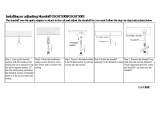
C1 Flue Restrictor Adjustment
The flue restrictors are adjusted by removing the firebox bae inside the firebox by removing a screw
in the centre rear of the bae; once removed the bae can be lifted up then out. The restrictors
are a simple sheetmetal part with a finger fold, allowing the installer to bend the flue restrictor open
or closed (flat) with his/her hands or pliers. The flue diagrams in section C7, C8, C9 & C10 refer to
dierent restrictor setups for dierent flue configurations. Use the following index for creating the
correct restriction:
C2 Installing False Cavity Flueing (if installing appliance into masonry, skip to C7)
Ensure all rigid flue components are Simpson Duravent Direct Vent Pro 4” x 6,” no other flue
types may be used.
Use the diagrams in sections C7, C8, C9 & C10 to check if your proposed flue system is
acceptable. Section C11 will also need to be used to determine whether the flue terminal
location meets the requirements of AS/NZS 5601. Then use the table following section C11 to work
out the quantities of the flue components that are required.
5
6
AF960 Restrictor SetupAF700 Restrictor Setup
N/A
N/A

B
A
CDEFGSERVICE
15
Rigid flue system rules for installation:
• The appliance comes with 300mm of flexi flue (compressed) and a converter box to convert the
appliance to rigid flueing.
• Any osets in your flue configuration should be 45° where possible.
• If your flue configuration has a horizontal run, there must be a minimum 1° inclination (20mm
vertical rise per 1m horizontal run) leading upwards towards the termination.
• Do not install the flue with horizontal sections sloping down towards the termination. This could
cause the fire to operate incorrectly and possibly create an unsafe condition.
• This flue system cannot be cut to length. Correct lengths must be selected for each installation.
For a full list of available flue lengths, contact your Escea retailer.
• The listed length of the flue pipe is not the installed length. 1 ½” (38mm) needs to be subtracted
for each join to determine the installed length of each piece of flue pipe.
E.g. 48” length has installed length of 45”.
• All vertical measurements should be measured from the top surface of the fireplace casing itself
(not the fascia).
• When using 90° elbows in the installation, use the diagram below to help calculate installations
horizontal and vertical distances. 1½” (38mm) will still need to be subtracted from each join.
• When using horizontal flue runs, vertical measurements should be measured to the centre line of
the horizontal flue pipes (as shown in diagram below).
• If using a 45° oset in your installation, consult the chart below to select the required flue length
to give the desired oset. 1½” (38mm) will still need to be subtracted from each of the 45° bends
to allow for the joins.

B
A
C D E F G SERVICE
16
• Adjustable lengths are available depending on stock levels. Contact escea for more information.
The flue must maintain the following clearances to combustible materials; 25mm from all sides and
bottom of the flue, and 50mm from the top of the flue:
C3 Supporting the Direct Vent flue system
Wall straps are required to fix the Direct Vent flue system in place for each installation. This will ensure
that no undue strain is placed on flue components once installed.
For a flue oset or horizontal run, it is recommended that wall straps be used to secure the flue system
with a spacing of 900mm between straps. Plumbers strapping / tape can be used to connect the wall
straps to the building structure where there are large distances between the support point and the
anchor point.
For vertical flue runs it is recommended that wall straps be used to anchor the flue system
with a spacing of 1200mm between straps.
C4 Sealing ‘Through Roof’ and ‘Through Wall’ Penetrations
For ‘through roof’ penetrations, use a Deck-tite flashing or equivalent to create a weather-tight seal
between the flue and the roof cladding.
For ‘through wall’ penetrations, this will require the use of a Wall Thimble. The Wall Thimble will ensure
you have suitable clearance from combustibles as well as sealing the penetration. The section of the
wall thimble installed on the external surface of the wall should be sealed to the wall using a high tem-
perature sealant such as a High Temperature RTV Silicone or equivalent. Additional sealant is required
to seal the Terminal Cap to the external wall. A bead should be run along the edge of the Terminal that
will be in contact with the wall once installed.

B
A
CDEFGSERVICE
17
C5 Twist locking procedure
Before connecting flue components, to ensure an airtight seal run a single 7-8mm bead of High Tem-
perature RTV Silicone or equivalent, on the ‘male’ end of the flue as shown in the diagram below.
The four indentations located on the female end of the flue are designed to slide straight onto the male
ends of the adjacent flue length, by orienting the four flue indentations so they match and slide into
the four entry slots on the male ends.
Push the pipe sections completely together, then twist-lock one section clockwise approximately
one-quarter turn, until the two sections are fully locked.
Wipe o any excess sealant from the exterior of the flue joint.
C6 Installing Converter Box
The AF-Series fireplace only comes with a spigot plate suited for flexi flue, because of this, a converter
box is required to convert a 300mm, 4” and 3” flexi flue length to Simpsons Duravent 4” x 6” direct
vent flueing.
The converter box must be appropriately secured and should not take the weight of the duravent rigid
flue; rigid flueing should be secured by wall straps as stated in section C3.
NOTE: The joists used to support the converter box from below MUST still maintain clearances from
the flexi pipes.
Combustible clearances for the converter box are as shown in a diagram in section B3

B
A
C D E F G SERVICE
18
Locate the 30cms long piece of fibreglass tape in the accessory pack provided with the
AF-Series fire.
Remove the tape backing and adhere it to the Exhaust spigot of the Co-axial transition box
spigot approximately 10mm o the face of the planer surface of the transition box.
Locate the 100mm exhaust flexi flue. Stretch the flexi flue to the desired length ensuring
that the end part that fits onto the exhaust spigot is completely extended (stretched).
Locate the exhaust flue onto the exhaust spigot over the fibreglass tape.
Locate 1 X 100mm diameter stainless steel band clamp provided with the flexi flue kit.
Mark, centre punch and drill 3 x 4.0mm diameter holes approximately equally spaced
around the diameter of the band clamp.

B
A
CDEFGSERVICE
19
Place the band clamp over the exhaust flexi flue. Position the band so that it aligns with the
fibreglass tape underneath (approximately 15mm o the planar surface of the transition
box). Tighten the band clamp.
ONLY TIGHTEN ENOUGH TO JUST HOLD AND PREVENT THE FLEXI FLUE FROM COM-
ING OFF THE SPIGOT IF PULLED ON. OVER TIGHTENING THE CLAMP WILL CRUSH &
DAMAGE THE FLEXI FLUE.
Pilot drill 3 X 3.00 diameter holes through the previously drilled holes in the band clamp and
into and through both the flexi flue and the exhaust spigot.
Screw a stainless steel self-tapping screw (provided with the fibre glass tape) into each of
the 3 holes.
Ensure that the joint is sound and secure.
The steel ‘flashing plate’ provided with the 46DVA-CT collinear kit may be used (if desired)
to force distances to combustible materials and provide a platform to screw onto
appropriately placed wooden joists (supports).
The joint on the 75mm intake spigot is achieved in the same manner however the fibreglass
tape is not required to be fitted to the intake spigot.

B
A
C D E F G SERVICE
20
C7 AF700 ONLY Vertically Terminating Flue Restriction Diagram
^AF700 ONLY^
Hybrid flueing: any length of flexi Flue or rigid Duravent may be used as long as the total length of
vertical flueing does not exceed 12m. The flexi flue must be used within masonry and convert to rigid
duravent immediately after exiting masonry.
NOTE: If your flue configuration falls on or near a restriction zone boundary line in diagrams located in
section C7, C8, C9 or C10 it may require the restriction setup from either side of the boundary line to
achieve the correct flame aesthetic (refer to E11 for flame aesthetic), this may vary from installation to
installation.
/