Page is loading ...

FCC Information
This is an FCC Class A product. In a domestic environment this product may cause
radio interference in which case the user may be required to take adequate measures.
This equipment has been tested and found to comply with the limits for a Class A
digital device, pursuant to Part 15 of the FCC Rules. These limits are designed to
provide reasonable protection against harmful interference when the equipment
is operated in a commercial environment. This equipment generates, uses and can
radiate radio frequency energy and, if not installed and used in accordance with
the instruction manual, may cause harmful interference to radio communications.
Operation of this equipment in a residential area is likely to cause harmful
interference in which case the user will be required to correct the interference at
his own expense.
© Copyright 2003 ALTUSEN
®
PAPE-0215-2AX
All brand names and trademarks are the registered property of their respective owners.
2003-07-23

Package Contents
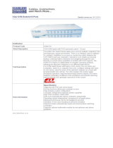
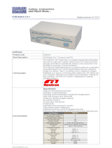
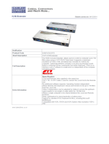
The complete KL0116 16-Port LCD Console KVM Switch package contains
the following components:
M 1 KL0116 KVM Switch
M 2 Custom KVM Cable Sets
M 1 Firmware Upgrade Cable
M 1Power Cord
M 1 Rack Mounting Kit (Optional)
M 1 User Manual
M 1 Quick Start Guide
M 1 Warranty / Registration Card
Check to make sure that all the components are present and in good order. If
anything is missing, or was damaged in shipping, contact your dealer.
Read this manual thoroughly and follow the installation and operation proce-
dures carefully to prevent damage to the switch or any of the devices that con-
nect to it.
2003-07-23
ii

Contents
About this Manual
Overview . . . . . . . . . . . . . . . . . . . . . . . . . . . . . . . vi
Conventions . . . . . . . . . . . . . . . . . . . . . . . . . . . . . vii
Getting Help
ALTUSEN Technical Support . . . . . . . . . . . . . . . . . . . viii
ALTUSEN Authorized Resellers . . . . . . . . . . . . . . . . . . viii
Chapter 1
Introduction
Overview . . . . . . . . . . . . . . . . . . . . . . . . . . . . . . . 1
Features . . . . . . . . . . . . . . . . . . . . . . . . . . . . . . . . 3
Benefits . . . . . . . . . . . . . . . . . . . . . . . . . . . . . . . . 4
Hardware Requirements . . . . . . . . . . . . . . . . . . . . . . . 4
Computers . . . . . . . . . . . . . . . . . . . . . . . . . . . . 4
Cables . . . . . . . . . . . . . . . . . . . . . . . . . . . . . . . 5
KL0116 Front View . . . . . . . . . . . . . . . . . . . . . . . . . . 6
KL0116 Rear View . . . . . . . . . . . . . . . . . . . . . . . . . . 9
Chapter 2
Installation
Single Stage Installation . . . . . . . . . . . . . . . . . . . . . . . 11
Daisy Chaining . . . . . . . . . . . . . . . . . . . . . . . . . . . . 12
Hot Plugging . . . . . . . . . . . . . . . . . . . . . . . . . . . . . 14
Switching Station Positions: . . . . . . . . . . . . . . . . . . . 14
Hot Plugging CPU Ports: . . . . . . . . . . . . . . . . . . . . . 14
Powering Off and Restarting . . . . . . . . . . . . . . . . . . . . . 14
Port ID Numbering . . . . . . . . . . . . . . . . . . . . . . . . . . 15
Port Selection . . . . . . . . . . . . . . . . . . . . . . . . . . . . . 15
2003-07-23
iii

Chapter 3
Hotkey Operation
Hotkey Port Access . . . . . . . . . . . . . . . . . . . . . . . . . 17
Invoking Hotkey Mode . . . . . . . . . . . . . . . . . . . . . 17
Selecting the Active Port . . . . . . . . . . . . . . . . . . . . . 18
Auto Scanning . . . . . . . . . . . . . . . . . . . . . . . . . . 19
Skip Mode . . . . . . . . . . . . . . . . . . . . . . . . . . . . 21
Hotkey Beeper Control . . . . . . . . . . . . . . . . . . . . . . . . 21
Hotkey Summary Table . . . . . . . . . . . . . . . . . . . . . . . 22
Chapter 4
OSD Operation
OSD Overview . . . . . . . . . . . . . . . . . . . . . . . . . . . . 23
OSD Navigation . . . . . . . . . . . . . . . . . . . . . . . . . . . 24
OSD Main Screen Headings . . . . . . . . . . . . . . . . . . . 25
OSD Functions . . . . . . . . . . . . . . . . . . . . . . . . . . . . 25
F1 GOTO: . . . . . . . . . . . . . . . . . . . . . . . . . . . . 26
F2 LIST: . . . . . . . . . . . . . . . . . . . . . . . . . . . . . 27
F3 SET: . . . . . . . . . . . . . . . . . . . . . . . . . . . . . . 28
F4 ADM: . . . . . . . . . . . . . . . . . . . . . . . . . . . . . 31
F5 SKP: . . . . . . . . . . . . . . . . . . . . . . . . . . . . . . 34
F6 BRC: . . . . . . . . . . . . . . . . . . . . . . . . . . . . . 35
F7 SCAN: . . . . . . . . . . . . . . . . . . . . . . . . . . . . 36
F8 LOUT: . . . . . . . . . . . . . . . . . . . . . . . . . . . . 37
Chapter 5
The Firmware Upgrade Utility
Before You Begin . . . . . . . . . . . . . . . . . . . . . . . . . . . 39
Starting the Upgrade . . . . . . . . . . . . . . . . . . . . . . . . . 40
Upgrade Succeeded . . . . . . . . . . . . . . . . . . . . . . . . . . 42
Upgrade Failed . . . . . . . . . . . . . . . . . . . . . . . . . . . . 42
Firmware Upgrade Recovery . . . . . . . . . . . . . . . . . . . . . 43
2003-07-23
iv

Chapter 6
Remote Console Operation
Installation . . . . . . . . . . . . . . . . . . . . . . . . . . . . . . 45
Operation . . . . . . . . . . . . . . . . . . . . . . . . . . . . . . . 46
Appendix
KL0116 Connection Table . . . . . . . . . . . . . . . . . . . . 47
OSD Factory Default Settings . . . . . . . . . . . . . . . . . . . . 48
Specifications . . . . . . . . . . . . . . . . . . . . . . . . . . . . . 49
LCD Operation Reference . . . . . . . . . . . . . . . . . . . . . . 50
Clear Login Information . . . . . . . . . . . . . . . . . . . . . . . 51
Module Removal . . . . . . . . . . . . . . . . . . . . . . . . . . . 52
Removing the KVM Module . . . . . . . . . . . . . . . . . . . 52
Removing the Keyboard and Touchpad . . . . . . . . . . . . . 53
Rack Mounting . . . . . . . . . . . . . . . . . . . . . . . . . . . . 54
Standard Rack Mounting . . . . . . . . . . . . . . . . . . . . . 54
Optional Rack Mounting . . . . . . . . . . . . . . . . . . . . . 54
Limited Warranty . . . . . . . . . . . . . . . . . . . . . . . . . . . 56
2003-07-23
v

About This Manual
This User Manual provides information concerning the installation, configura-
tion, and operation of the KL0116 16-Port LCD Console KVM Switch.
Overview
Chapter 1, Introduction, introduces you to the KL0116. Its purpose, features
and benefits are presented, and its front and back panel components are described.
Chapter 2, Installation explains how to set up your installation — from a basic
single stage hookup to a complete three stage operation.
Chapter 3, Hotkey Operation, details the procedures used in the Hotkey
operation of your KL0116 installation.
Chapter 4, OSD Operation, provides a complete description of the KL0116’s
OSD (On Screen Display), and explains the procedures usded to manipulate it.
Chapter 5, The Firmware Upgrade Utility, describes how to upgrade the
KL0116’s firmware with the latest available version.
Chapter 6, Remote Console Operation, explains how to operate the
KL0116 from a remote console (up to 150 meters / 500 feet away).
An Appendix provides technical and other important information regarding the
KL0116.
2003-07-23
vi

Conventions
This manual uses the following conventions:
Courier
Indicates text that you should key in.
[ ]
Indicates keys you should press. For example, [Enter] means to
press the Enter key. If keys need to be chorded, they appear
together in the same bracket with a plus sign between them:
[Ctrl+Alt].
1.
Numbered lists represent procedures with sequential steps.
M
Bullet lists provide information
>
Indicates selecting an option on a menu. For example, Start >
Run means to open the Start menu, and then select Run.
Indicates critical information.
Getting Help
For additional help, advice, and information, ALTUSEN provides several sup-
port options. If you need to contact ALTUSEN technical support with a prob-
lem, please have the following information ready beforehand:
M Product model number, serial number, and date of purchase.
M Your computer configuration, including operating system, revision level,
expansion cards, and software.
M Any error messages displayed at the time the error occurred.
M The sequence of operations that led up to the error.
M Any other information you feel may be of help.
2003-07-23
vii

ALTUSEN Technical Support
North America Technical
Phone Support
Registered ALTUSEN product owners are entitled to
telephone technical support. Call the ALTUSEN
Technical Support Center: 949-453-8885.
International Technical Phone
Support
1. Contact your local dealer.
2. Call the ALTUSEN Technical Support Center:
1-949-453-8885.
Email Support Email your questions and concerns to:
Online Troubleshooting The ALTUSEN support website:
http://www.altusen.com/support
provides online troubeshooting that describes the
most commonly encountered problems and offers
possible solutions to them.
Online Documentation User Manuals are available electronically at the
ALTUSEN support website:
http://www.altusen.com/support
Software Updates Download the latest drivers and firmware for your
product from the ALTUSEN support website:
http://www.altusen.com/support
Product Information
For information about all of ALTUSEN’s products and how they can help you
connect without limits, visit ALTUSEN on the webat http://www.altusen.com
ALTUSEN Authorized Resellers
ALTUSEN provides the following ways to find an authorized reseller in your area:
M In the United States of America, call: 866-ALTUSEN
M In Canada and South America, call: 949-453-8885
M In all other locations, call: 886-2-8692-6959
M Visit ALTUSEN on the web at http://www.altusen.com for a list of locations
and telephone numbers
2003-07-23
viii

Chapter 1.
Introduction
Overview
The ALTUSEN 16-Port LCD Console KVM Switch offers a highly efficient
network management solution. Custom designed high-density CPU connectors
allow a 16-port KVM switch to fit into a 1U high rack space. Additional AL-
TUSEN switches can be daisy chained to the KL0116, allowing up to 512 com-
puters to be controlled from its LCD console.
The KL0116 offers many advanced features, such as intuitive On Screen Dis-
play (OSD), Hotkeys, excellent video resolution, two level User password secu-
rity with different security clearances, and flash ROM for firmware upgrades.
The ALTUSEN KL0116 offers a space-saving, streamlined approach to KVM
switch technology, integrating a keyboard, LCD monitor, and touchpad in a 1U
high slide-out housing. The LCD display is built into the cover, and the key-
board and trackball are built into the base. Simply slide the KVM module sec-
tion out; flip the cover up; and you are ready to go to work. The KL0116’s
modular design also allows you to detach the KVM module from the switch
module for maintenance.
For further convenience, the switch can be operated from an independent, exter-
nal KVM console with the addition of an ALTUSEN Console Extender (not in-
cluded). The KL0116 also features high density 15 pin connectors instead of
the usual 25 pin connectors. This space-saving innovation allows installation of
a full, 16 port switch in a 1U system rack.
An included Firmware Upgrade Utility protects your KL0116 investment. You
can stay current with the latest functionality imporvements by downloading
firmware update files from the ALTUSEN website as they become available,
and use the utility to quickly and conveniently perfrom upgrades.
Setting up the KL0116 is fast and easy, consisting of plugging cables into their
appropriate ports. Because the KL0116 intercepts keyboard input directly, there
is no software to configure, and therefore no complex installation routines or in-
compatibility problems.
2003-07-25
1

You can easily access to any computer on the installation either by entering
Hotkey combinations from the keyboard, or by using the powerful menu driven
OSD system. A convenient Auto Scan feature also permits automatic scanning
and one-by-one monitoring of the activities of selected computers.
2003-07-25
2

Features
The main features of the KL0116 are as follows:
w A single slide-out console integrated with the KVM switch controls up to 16
computers directly
w Slide-out console features a 15" LCD monitor that can tilt back to a 30
o
viewing angle.
w Modular design - the keyboard and touchpad module, as well as the KVM
Switch module, are easily removed for convenient maintenance
w Dedicated chain ports to link up to 31 additional High Density KVM
Switches (model KH0116) to control up to 512 computers from the slide-out
console
w Plug-n-Play; no software required
w Convenient computer selection via intuitive On Screen Display (OSD)
menus, Hotkeys, or pushbutton switches
w Remote console port for optional control of servers from up to 500 feet away
w Auto Scan feature for monitoring selected computers
w Hot pluggable - add or remove computers without having to power down the
switch
w Auto-sensing of station position on daisy chained installations - no need for
manual DIP switch setting
w Port names automatically reconfigured when station sequence is changed
w Two level password security - up to four authorized Users and an
Administrator view and control the computers, with separate profiles for each
w Two level logout - manual and timed
w PS/2 keyboard and mouse emulation allows computers to boot the even
when they are not selected
w 15" RGB analog LCD display supporting high XGA resolutions of up to
1024 x 768 with 250 cd/m2 brightness
w Firmware upgradable via flash ROM
w Full range universal internal power supply (AC 100-240 V)
w Console Lock - keeps the sliding console securely locked away when not in
use
2003-07-25
3

Benefits
The KL0116 saves time and money by allowing a single console to manage all
of your computers. Specifically, the benefits of a KL0116 installation are these:
w Eliminates the expense of purchasing a keyboard, monitor, and mouse for
each computer
w Eliminates the space needed for the extra KVM components
w More efficient use of space than standard KVM switches
w Saves on energy costs
w Eliminates the inconvenience and effort required to physically move from
one computer to another
Hardware Requirements
Computers
The following equipment must be installed on each computer:
w A VGA, SVGA or Multisync card.
Note: Since the integrated LCD monitor’s maximum resolution is 1024 x
768, the video resolution settings for each computer must not
exceed 1024 x 768.
w A 6-pin mini-DIN (PS/2 style) mouse port.*
w Either a 6-pin mini-DIN (PS/2 Style) keyboard port with +5V DC on pin 4
and Ground on pin 3, or a 5-pin DIN (AT Style) keyboard port with +5V DC
on pin 5 and ground on pin 4.*
* 1. See the note under Cables on p. 5.
2. For Mac, Sun, and Linux computers, PS/2 to USB converters are
required. If you plan to use these on your KL0116 installation, see
your dealer for details
2003-07-25
4

Cables
Substandard cables may damage the connected devices or degrade overall perform-
ance. For optimum signal integrity and to simplify the layout, we strongly recom-
mend that you use the high quality CS Custom Cable sets described below:
Function CS Part Number
KVM Switch to KVM Switch (Daisy Chaining) KL1700 - 0.6 m
KL1701 - 1.8 m
KVM Switch to Computer KL5201P - 1.2 m
KL5202P - 1.8 m
KL5203P - 3.0 m
Note: 1. The KL0116 does not support serial mice. You cannot use
Serial-to-PS/2 adapters with the cables.
2. If your computer uses an AT style keyboard socket you will need to
purchase a PS/2-to-AT keyboard adapter in order to plug the cable
into the computer’s keyboard port.
KC1700 / KC1701 KC5201P / KC5202P / KC5203P
2003-07-25
5

KL0116 Front View
1. Handle
Pull the handle to slide the KVM module out; push to slide the module in.
2. LCD Screen
3. Port Selection Switches / Port LEDs
Press a switch to bring the KVM focus to its corresponding port.
Note: 1. You must be logged in to use these switches. Otherwise, pressing
them will have no effect.
2. The focus will only switch to ports that you have access rights to
(see SET ACCESSIBLE PORTS, p. 1-33). If you don’t have
access rights to a port, pressing the switch will have no effect.
w Pressing Buttons 1 and 2 for three seconds performs a keyboard and
mouse reset.
w Pressing Buttons 15 and 16 for three seconds initiates Auto Scan Mode
(see p. 20, and F7 SCAN, p. 36).
1
2
3
4
5
8
6
7
10
9
2003-07-25
6

Two LEDs are built into each selection switch. The one on the left is the On
Line LED; the one on the right is the Selected Port LED:
w An On Line LED lights GREEN to indicate that the device attached to
its corresponding port is up and running.
w A Selected LED lights AMBER to indicate that its corresponding port is
the one that has the KVM focus. The LED is steady under normal
conditions, but flashes when its port is accessed under Auto Scan Mode
(see F7 SCAN, p. 36).
w Each time the KL0116 is powered on, the On Line and Selected LEDs
blink in sequence as the Switch performs a self-test.
4. Keyboard
Note: The special functions for the F6, F9, F10, F11, and F12 function
keys as well as the Esc and Z keys (the functions that are enabled
when the Fn key is held down), are not supported at this time.
5. Touchpad
6. Power LED
Lights BLUE to indicate that the unit is receiving power.
7. Console Release
The KL0116 has a mechanism that locks it in the “In” position to prevent it
from accidentally sliding out. To slide the console out, push this tab
sideways.
8. Rack Mounting Brackets
There are rack mounting brackets attached to each corner of the unit. They
are used to secure the chassis to a system rack.
2003-07-25
7

9. Reset Switch
Pressing this switch in performs a system reset. This switch is recessed and
must be pushed with a thin object - such as the end of a paper clip, or a
ballpoint pen.
10. LCD Display Controls
w Buttons to control the position and picture settings of the LCD display
are located here, as well as a buton to Enable/Disable operating the
KL0116 from an optional remote console. See the Remote Console
Operation chapter (p. 45) and the LCD Operation section (p. 50) for
details.
w The Local and Remote LEDs light to indicate that their respective
consoles are active.
2003-07-25
8

KL0116 Rear View
1. Power Switch
This is a standard rocker switch that powers the unit On and Off.
2. Power Socket
The AC power cord plugs in here.
3. Daisy Chain Port
When Daisy Chaining Units, the Daisy Chain cable plugs in here.
4. CPU Port Section
The KVM cables that link to the computers plug in here. Because of the
connector shape, only cables designed to work with this switch (see p. 5)
can plug in. Do NOT attempt to use ordinary 15 pin VGA connector cables
to link these ports to the computers.
Note: See the Cables section, p 5, for detailed information about cables.
1 2 34
4
5 6 7
2003-07-25
9

5. Remote Console Port
The KL0116 can be operated from a remote console up to 500 feet (150
meters) away with the optional purchase of a KA9250 Console Extender
Module. If the Extender Module is used, its cable plugs into this RJ-45
connector. See the Remote Console Operation chapter (p. 45) and the LCD
Operation section (p. 50) for details about remote console operation.
6. Firmware Upgrade Port
The KL0116’s firmware can be upgraded. To perform an upgrade, the
Firmware Upgrade Cable plugs into this RJ-11 connector (see p. 39 for
details).
7. Firmware Upgrade Recovery Switch
This switch should be in the NORMAL position during normal operation
and while performing a fimware upgrade. See p. 43 for further details about
the use of this switch.
2003-07-25
10

Chapter 2.
Installation
Single Stage Installation
In a Single Stage installation, there are no additional switches daisy chained
down from the first unit. To set up a single stage installation do the following:
1. Use KVM cable sets (as described in the Cables section on p. 5), to connect
any available CPU Port to the Keyboard, Video and Mouse ports of the
computer you are installing.
Note: Disregard the Daisy Chain Port at this time. It is only used for daisy
chaining a KH0116 switch to the KL0116. Daisy chaining is
described in the next section of this chapter.
2. Plug the female end of the power cable into the KL0116’s Power Socket,
then plug the male end into an AC power source.
3. Turn on the power to the KL0116.
4. Turn on the power to the computers.
2003-07-25
11

Daisy Chaining
To control even more computers, up to 31 additional ALTUSEN KVM
switches can be daisy chained down from the KL0116.
Note: KH0116 switches are used for daisy chaining, since there is no need for
consoles on the chained switches. The KH0116 is similar to the
KL0116, except that it comes in a standard housing without the
slide-out console. Tables showing the relation between the number of
computers and the number of switches needed to control them are
provided on p. 47.
To set up a daisy chained installation, do the following:
1. Turn off the power to all the devices you will be connecting to the
installation.
2. Use a daisy chain cable set (described in the Cables section, p. 5), to
connect the KL0116’s Daisy Chain Portto the first KH0116’s Chain In port.
Note: 1. The KL0116 is referred to as the First Station; the first KH0116
in the chain is the Second Station, etc.
2. In a daisy chained installation, a switch is the child of the switch
above it, and the parent of the switch below.
2003-07-25
12
/