Page is loading ...

4K DVI Protector
Article No: RGB-RD-UM-4K DVI
Protector E000
Revision No: V1.0
USER MANUAL

FLEX4ML User Manual
1
CONTENTS
Declarations
...................................................................................................................................................
2
FCC/Warranty
........................................................................................................................................
2
Operators Safety Summary
.................................................................................................................
3
Installation Safety Summary
...............................................................................................................
3
Chapter 1 Your Product
................................................................................................................................
5
1.1 Packing
...............................................................................................................................................
5
1.2 Product Overview
..............................................................................................................................
5
1.3 Dimension
..........................................................................................................................................
6
Chapter 2
Use
Your Product
......................................................................................................................
7
2.1 Stucture and Performance
.................................................................................................................
7
2.2 Main Features
....................................................................................................................................
7
2.2.1 Mechanical Damage Protection
.............................................................................................
7
2.2.2 ESD Protection
........................................................................................................................
7
2.2.2 Signal Indication
......................................................................................................................
8
2.3 Questions and Troubleshooting
.........................................................................................................
8
CHAPTER 3 ORDERING CODES
.............................................................................................................
9
3.1 Product
...............................................................................................................................................
9
3.2 Compatibility
......................................................................................................................................
9
CHAPTER 4 Support
.................................................................................................................................
10
4.1 Contact Us
........................................................................................................................................
10
CHAPTER
5
APPENDIX
............................................................................................................................
11
5.1 Specification
.....................................................................................................................................
11
5.2 Terms & Definitions
.........................................................................................................................
12
5.3 Revison History
................................................................................................................................
13

4K DVI Protector User Manual
2
Thank you for choosing our product!
This User Manual is designed to show you how to use this video processor quickly and
make use of all the features. Please read all directions and instructions carefully before
using this product.
Declarations
FCC/Warranty
Federal Communications Commission (FCC) Statement
This equipment has been tested and found to comply with the limits for a class A digital device,
pursuant to Part 15 of the FCC rules. These limits are designed to provide reasonable protection
against harmful interference when the equipment is operated in a commercial environment. This
equipment generates, uses, and can radiate radio frequency energy and, if not installed and used
in accordance with the instruction manual, may cause harmful interference to radio
communications. Operation of this equipment in a residential area may cause harmful
interference, in which case the user will be responsible for correcting any interference.
Guarantee and Compensation
RGBlink provides a guarantee relating to perfect manufacturing as part of the legally
stipulated terms of guarantee. On receipt, the purchaser must immediately inspect all
delivered goods for damage incurred during transport, as well as for material and
manufacturing faults. RGBlink must be informed immediately in writing of any complains.
The period of guarantee begins on the date of transfer of risks, in the case of special systems
and software on the date of commissioning, at latest 30 days after the transfer of risks. In the
event of justified notice of compliant, RGBlink can repair the fault or provide a replacement at its
own discretion within an appropriate period. If this measure proves to be impossible or
unsuccessful, the purchaser can demand a reduction in the purchase price or cancellation of the
contract. All other claims, in particular those relating to compensation for direct or indirect
damage, and also damage attributed to the operation of software as well as to other service
provided by RGBlink, being a component of the system or independent service, will be deemed
invalid provided the damage is not proven to be attributed to the absence of properties
guaranteed in writing or due to the intent or gross negligence or part of RGBlink.
If the purchaser or a third party carries out modifications or repairs on goods delivered by
RGBlink, or if the goods are handled incorrectly, in particular if the systems are commissioned
operated incorrectly or if, after the transfer of risks, the goods are subject to influences not
agreed upon in the contract, all guarantee claims of the purchaser will be rendered invalid. Not
included in the guarantee coverage are system failures which are attributed to programs or
special electronic circuitry provided by the purchaser, e.g. interfaces. Normal wear as well as

4K DVI Protector User Manual
3
normal maintenance are not subject to the guarantee provided by RGBlink either.
The environmental conditions as well as the servicing and maintenance regulations specified in
this manual must be complied with by the customer.
Operators Safety Summary
The general safety information in this summary is for operating personnel.
Do Not Remove Covers or Panels
There are no user-serviceable parts within the unit. Removal of the top cover will expose
dangerous voltages. To avoid personal injury, do not remove the top cover. Do not operate the
unit without the cover installed.
Power Source
This product is intended to operate from a power source that will not apply more than 230 volts
rms between the supply conductors or between both supply conductor and ground. A protective
ground connection by way of grounding conductor in the power cord is essential for safe
operation.
Grounding the Product
This product is grounded through the grounding conductor of the power cord. To avoid electrical
shock, plug the power cord into a properly wired receptacle before connecting to the product
input or output terminals. A protective-ground connection by way of the grounding conductor in
the power cord is essential for safe operation.
Use the Proper Power Cord
Use only the power cord and connector specified for your product. Use only a power cord that is
in good condition. Refer cord and connector changes to qualified service personnel.
Use the Proper Fuse
To avoid fire hazard, use only the fuse having identical type, voltage rating, and current rating
characteristics. Refer fuse replacement to qualified service personnel.
Do Not Operate in Explosive Atmospheres
To avoid explosion, do not operate this product in an explosive atmosphere.
Installation Safety Summary
Safety Precautions
For all installation procedures, please observe the following important safety and handling rules
to avoid damage to yourself and the equipment.

4K DVI Protector User Manual
4
To protect users from electric shock, ensure that the chassis connects to earth via the ground
wire provided in the AC power Cord.
The AC Socket-outlet should be installed near the equipment and be easily accessible.
Unpacking and Inspection
Before opening shipping box, inspect it for damage. If you find any damage, notify the shipping
carrier immediately for all claims adjustments. As you open the box, compare its contents against
the packing slip. If you find any shortages, contact your sales representative.
Once you have removed all the components from their packaging and checked that all the listed
components are present, visually inspect the system to ensure there was no damage during
shipping. If there is damage, notify the shipping carrier immediately for all claims adjustments.
Site Preparation
The environment in which you install your product should be clean, properly lit, free from static,
and have adequate power, ventilation, and space for all components.

4K DVI Protector User Manual
5
Chapter 1 Your Product
1.1 Packing
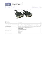
1.2 Product Overview
4K DVI Protector is designed to protect the DVI connectors on source or display
devices. It can protect DVI connector against mechanical damage due to frequent
plug in and out. While delivering UHD video signal it indicates signal connection by a
small embedded blue LED light and offers up to 15KV ESD protection against electric
shock and burning.
RGBlink video processing solutions provide a range of flexible configuration options
for professional applications.
4K DVI Protector System Connection Diagram
1 pc per bag
10pcs per box
System Connection

4K DVI Protector User Manual
6
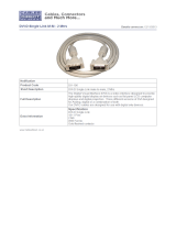
1.3 Dimension
Following is the dimension of 4K DVI Protector for your reference:

4K DVI Protector User Manual
7
Chapter 2 Use Your Product
2.1 Stucture and Performance
L*W*H:40.9*39*17cm
Input Connector:DVI-FEMALE 24+5 , white rubber core plated with gold
Output Connector:DVI-MALE 24+1, white rubber core plated with gold
Connector plating:1u” gold
Shell plating
:
1u”gold
Body plating
:
50 u”nickle
Insertion force
:
44.1N(MAX)
Withdrawal force:39.2N(MAX)---9.8N(MIN)
2.2 Main Features
2.2.1 Mechanical Damage Protection
Connect 4K DVI protector male port to DVI connector on devices and plug digital video cable to female
port of 4K protector. In this way, DVI connectors on devices can avoid mechanical damage due to rough
or incorrect operation.
DVI protectors can fit connector as follow:
Type
Signal
Pin
DVI-I Single Link
Digital/Analog
18+5
DVI-I Dual Link
Digital/Analog
24+5
DVI-D Single Link
Digital
18+1
DVI-D Dual Link
Digital
24+1
2.2.2 ESD Protection
ESD chip embedded in 4K DVI Protector offers ESD protection to the connectors and mainboard against
all static electricity from clock signal ,human body, devices and surrounding environment.

4K DVI Protector User Manual
8
2.2.2 Signal Indication
4K DVI Protector is built with a led indicator light which illuminates when there is video signal pass
through, no signal or the connection cable is loose, it doesn’t light up.
There are several reasons if the led indicator doesn’t light up.
LED indicator Off
LED Indicator On
4K DVI protector plug into source device, but
no video cable to connect
4K DVI protector plug into source device and
cable connection to Display is right.
4K DVI protector plug into source device, but
video cable connection goes wrong
Correct cable connection but the Display is on
Standby mode or Display is off.
2.3 Questions and Troubleshooting
2.3.1 Yellow Characters
Question:After using 4K DVI Protector, characters or words on 4K@60Hz video gets yellow, why is that?
Solution:First of all, make sure the cable used in the connection can support 4K@60Hz video, then find
out if the connector between cable, protector and device are loose, if loose, lock them.
2.3.1 Flashing Points
Question:After using 4K DVI Protector,flashing points occurs, why is that?
Solution: Check the connection between protector and device, if it get loose, tighten the connection,
flashing points will disappear.

4K DVI Protector User Manual
9
CHAPTER 3 ORDERING CODES
3.1 Product
Product Code
Item
920-0006-01-0
4K DVI Protector
3.2 Compatibility
DVI protector can be used together with following product:
Product Code
Item
921-0000-50-0
DVI-DVI Digital Video Cable, with Cap, 0.5m
921-0001-50-0
DVI-DVI Digital Video Cable, with Cap,1.5m
921-0002-01-0
DVI-DVI Digital Video Cable, with Cap, 2m
921-0003-01-0
DVI-DVI Digital Video Cable, with Cap, 3m
921-0005-01-0
DVI-DVI Digital Video Cable, with Cap, 5m
922-0001-50-0
HDMI-DVI Digital Video Cable, with Cap, 1.5m
922-0002-01-0
HDMI-DVI Digital Video Cable, with Cap2m,
(
with steel nail
)
922-0002-01-1
HDMI-DVI Digital Video Cable, with Cap2m
(
without steel nail
)
922-0003-01-0
HDMI-DVI Digital Video Cable, with Cap, 3m
922-0005-01-0
HDMI-DVI Digital Video Cable, with Cap, 5m
923-0002-01-0
HDMI-HDMI Digital Video Cable, with Cap, 2m
(
with steel nail
)
923-0002-01-1
HDMI-HDMI Digital Video Cable, with Cap, 2m
(
without steel nail
)
923-0003-01-0
HDMI-HDMI Digital Video Cable, with Cap, 3m
923-0005-01-0
HDMI-HDMI Digital Video Cable, with Cap, 5m
923-0010-01-0
HDMI-HDMI Digital Video Cable, with Cap, 10m
927-0030-00-0
DP-DVI Premium Adapter

4K DVI Protector User Manual
10
CHAPTER 4 Support
4.1 Contact Us

4K DVI Protector User Manual
11
CHAPTER 5 APPENDIX
5.1 Specification
Connectors
Input
DVI-D (male)24+1
Output
DVI-I (female)24+5
Performance
Input Resolution
SMPTE
720p@60 |1080p@60 | 2160p@30/60
VESA
1280×720@60 | 1360×768@60 | 1366×768@60 |
1600×900@60 |
1920×1080@60 | 1920×1200@60 | 2540×1440@60 |
3840×2160@30/60 | 7680×1080@60
Output Resolution
SMPTE
720p@60 |1080p@60 | 2160p@30/60
VESA
1280×720@60 | 1360×768@60 | 1366×768@60
|1600×900@60 |
1920×1080@60 | 1920×1200@60 | 2540×1440@60 |
3840×2160@30/60| 7680×1080@60
Supported
Standards
DVI
Dual Link
HDMI
2.0
Power
Source
Male
Environment
Temperature
-10
℃
~5
0
℃
Humidity
10%~
85%
Physical
Weight
40.9mm×39mm×17mm
Dimension
0.048kg
Extras
Storage Environment
20°C~80°C
Stored Environment
5% to 90%
Product Warranty
3 years parts and labor warranty

4K DVI Protector User Manual
12
5.2 Terms & Definitions
●DVI :
Digital Visual Interface. The digital video connectivity standard that was developed by
DDWG (Digital Display Work Group). This connection standard offers two different connectors:
one with 24 pins that handles digital video signals only, and one with 29 pins that handles both
digital and analog video.
DVI-I Connector
Pin
Function
Pin
Function
1
TMDS Data 2-
13
TMDS Data 3+
2
TMDS Data 2+
14
+5V DC power supply
3
TMDS Data 2/4
Shielding
15
Ground(+5 Loop)
4
TMDS Data
16
Hot plug detecting
5
TMDS Data
17
TMDS Data 0-
6
DDC Clock
18
TMDS Data 0+
7
DDC Data
19
TMDS Data 0/5 Shielding
8
Analog Genlock V
20
TMDS Data 5-
9
TMDS Data 1-
21
TMDS Data 5+
10
TMDS Data 1+
22
TMDS Data Clock Shielding
11
TMDS Data 1/3
Shielding
23
TMDS Data Clock+
12
TMDS Data 3-
24
TMDS Data Clock-
C1
Analog Genlock V
C4
Analog Genlock H
C2
Analog Green
C5
Analog ground(RGB Loop)
C3
Analog Blue

4K DVI Protector User Manual
13
5.3 Revison History
The table below lists the changes to the Video Processor User Manual.
Version
Time
ECO#
Description
Editor
V1.0
20200512
0000
Release
Fanny
/