Page is loading ...

Danfoss scroll compressors
VLZ028-035-044
Single
R404A/R448A/R449A
Application guidelines
http://cc.danfoss.com


Content
GENERAL INFORMATION .........................4
PRODUCT INFORMATION .......................5
Features......................................................5
Compressor model designation ..............6
Nomenclature ............................................................ 6
Technical specications ............................7
Dimensions ................................................9
Single compressors .................................................. 9
Electrical data, connections and wiring 12
Supply voltage ......................................................... 12
Phase sequence and reverse rotation
protection .................................................................. 14
IP rating ....................................................................... 15
Motor protection.....................................................15
Approval and certicates .......................16
Low voltage directive 2014/35/EU .................... 16
Internal free volume...............................................16
SYSTEM DESIGN ..................................... 17
Design piping ..........................................17
General requirements ........................................... 17
Design compressor mounting ...............18
General requirements ........................................... 18
Single requirements...............................................18
Manage oil in the circuit .........................19
Requirement .............................................................19
System evaluation .................................................. 19
Test, criteria and solutions ...................................19
Manage sound and vibration ................ 20
Compressor sound radiation .............................. 20
Mechanical vibrations ........................................... 21
Gas pulsation ............................................................ 21
Manage operating envelope ................. 22
Requirement ............................................................. 22
Speed limit requirement ...................................... 24
Start/Stop/Ramp setting ...................................... 24
Short cycle protection .........................................25
Manage superheat ................................. 26
Requirement ............................................................. 26
System evaluation ..................................................26
Test, criteria and solutions ................................... 27
Manage o cycle migration ................... 28
Requirement ............................................................. 28
System evaluation .................................................28
Provide power supply and electrical
protection ............................................... 30
Wiring diagram of CDS803 ..................................30
Wiring connections of CDS803 .......................... 31
Soft-start control .....................................................31
Control logic ........................................... 32
Safety control logic requirements ....................32
Defrost cycle logic ..................................................33
Pump-down logic recommendations .............33
Oil management logic ..........................................34
Reduce moisture in the system ............. 35
Requirements ........................................................... 35
Solutions ....................................................................35
INTEGRATION INTO SYSTEMS .............. 36
Assembly line procedure ....................... 36
Compressor storage ...............................................36
Compressor holding charge ...............................36
Handling ....................................................................36
Piping assembly.......................................................37
System pressure test and leak detection ....... 37
Vacuum evacuation and moisture removal . 38
Refrigerant charging ..............................................38
Dielectric strength and insulation resistance
tests .............................................................................. 38
Commissioning ....................................... 39
Preliminary check....................................................39
Initial start-up ........................................................... 39
System monitoring ................................................. 39
Oil level checking and top-up ............................ 39
Troubleshooting ..................................... 40
Dismantal and disposal ......................... 43
ORDERING INFORMATION ...................44
Packaging ............................................... 44
Ordering codes ....................................... 45
Accessories .............................................. 46
3FRCC.PC.052.A2.02

PRODUCT INFORMATIONSYSTEM DESIGNINTEGRATION INTO SYSTEMORDERING INFORMATION GENERAL INFORMATION
General Information
Danfoss scroll compressors are designed and
manufactured according to the state of the
art and to valid European and US regulations.
Particular emphasis has been placed on
safety and reliability. Related instructions are
highlighted with the following icons:
This icon indicates instructions to avoid
safety risk.
This icon indicates instructions to avoid
reliability risk.
The purpose of this guideline is to help
customers qualify compressors in the unit.
You are strongly advise to follow these
instructions. For any deviation from the
guidelines, please contact Danfoss Technical
Support. In any case, Danfoss accepts no
liability as a result of the improper integration
of the compressor into the unit by the system
manufacturer.
R
4 FRCC.PC.052.A2.02

GENERAL INFORMATIONSYSTEM DESIGNINTEGRATION INTO SYSTEMORDERING INFORMATION PRODUCT INFORMATION
Features
Intermediate discharge
valves for better eciency
at low pressure-ratio
Scrolls with optimized
volume ratio lead to better
performance
New distributed IPM
motor lead to higher
power factor
Linear control oil pump
POE46 lubricant
EMC (Electro-Magnetic
Compatibility) bracket
provided allows for
grounding termination
of shielded wire-harness,
which reduces EMC
emissions between drive
and compressor
5FRCC.PC.052.A2.02

GENERAL INFORMATIONSYSTEM DESIGNINTEGRATION INTO SYSTEMORDERING INFORMATION PRODUCT INFORMATION
Compressor model designation
Nomenclature
Compressor nomenclature
Frequency converter
nomenclature
AE9NGT044LZV
Variable speed
Family
Scroll (refrigeration)
Lubricant
POE46(RL46HB) lubricant
R404A/R448A/R449A refrigerant
Swept volume
in cm³/rev
Design pressure ratio
T: Design optimized for
refrigeration
Evolution index
Other features
Fittings/connections
Brazed connections, EMC
compatible terminal box
Motor protection type
N: no internal motor protection
(protection by Danfoss drive)
Motor voltage code to CDS303 *
G: 380-480V/3~/50 & 60Hz
J: 200-240V/3~/50 & 60Hz
* main supply voltage to frequency converter
9Threaded None Schrader
Oil sight glass Oil equalization Oil drain
H4E20T4P7K5803CDS
Dedicated compressor
drive for VLZ scroll
Serie 803
Output power
in kW
Main supply voltage
T2: 200-240V/3 ph/50-60 Hz
T4: 380-480V/3 ph/50-60 Hz
RFI class
Enclosure protection
IP rating
P7K5
6 FRCC.PC.052.A2.02

GENERAL INFORMATIONSYSTEM DESIGNINTEGRATION INTO SYSTEMORDERING INFORMATION PRODUCT INFORMATION
Technical specications
To have the optimum compressor selection,
select a compressor size which achieves the
peak load system cooling capacity demand at its
maximum speed.
Detailed performances can be found in
datasheets and in selection programs.
Compressor size
Dierent frequency converter variants are
available according to:
1. Mains supply voltage
2. IP class
3. RFI (Radio Frequency Interference) class H4
4. Printed Circuit Board (PCB) coated
When the compressor size and mains voltage
have been dened in the above selection criteria,
the code number tables from the “Ordering
information and packaging” section provides the
appropriate frequency converter sizes.
Note this compressor is equipped with
a four-pole electrical motor so the applied
frequency from the inverter will be 60 Hz
for 30rps(1800 rpm) up to 200 Hz for 100
rps(6000 rpm).
Please refer to the table below
Frequency converter
variants
Compressor and
frequency converter
combinations
min max
Compressor speed
rps 30 100
rpm 1800 6000
Drive output frequency Hz 60 200
7FRCC.PC.052.A2.02

GENERAL INFORMATIONSYSTEM DESIGNINTEGRATION INTO SYSTEMORDERING INFORMATION PRODUCT INFORMATION
Technical specications
Compressor
specications
Frequency converter
specications
POE
R448A & R449A
R404A
Compressor model
Swept
volume
(cm³/rev)
Displacement
Oil charge
(Liters)
Net weight
(kg)
30 rps
(m³/h)
50 rps
(m³/h)
60 rps
(m³/h)
100 rps
(m³/h)
VLZ028 27.8 3.0 5.0 6.0 10.0 1.1 26
VLZ035 34.9 3.8 6.3 7.5 12.6 1.3 27
VLZ044 44.5 4.8 8.0 9.6 16.0 1.3 27
Mains supply voltage
CDS803-T2: 200 - 240 V +/-10% (3-phase)
CDS803-T4: 380 - 480 V +/-10% (3-phase)
Supply frequency 50 / 60 Hz
Output voltage 0 - 100 % of supply voltage
Standby power
T2: P7K5: 23.17W
T4: P7K5: 11.3W
Inputs CDS803: 4 digital (0 - 24 V), 2 analog (0 /±10 V or 4 - 20 mA, scalable)
Programmable outputs CDS803: 2 digital (0- 24 V), 2 analog (0-24 V), 2 relay
Protection functions Over-current protection, low / high current handling
Compressor functions
Pressostat / thermostat function, short cycle protection, oil return
management
The POE oil RL46HB(215PZ) is an ISO VG 46
synthetic polyol ester (POE) lubricant formulated
specically for use in refrigeration and air
conditioning compressors using HFC refrigerants.
This product provides eective wear protection
for steel and aluminum surfaces for increased
system life and improved eciency and is
suitable for both initial ll and service ll. The
combination of low temperature characteristics
and unparalleled chemical and thermal stability
enable the use of RL46HB over a wide operating
temperature range.
R448A and R449A are two HFO-based
refrigerants with similar properties. Both have a
GWP below 1500 and comply with the EU F-gas
regulation.
They can be used as alternatives to R404A
refrigerants in MBP application.
R448A&R449A have zero ozone depletion
potential (ODP = 0). R448A&449A are especially
suitable for low evaporating temperature
applications but they can also be applied to
medium evaporating temperature applications.
R448A &449A are mixtures and have big
temperature glide, and therefore must be
charged in their gas phase.
R404A is an HFC refrigerant. R404A has zero
ozone depletion potential (ODP = 0). R404A is
also suitable for low evaporating temperature
applications but it can also be applied to medium
evaporating temperature applications. R404A is a
mixture and has a very
small temperature glide, and therefore must be
charged in its liquid phase, but for most other
aspects this small glide can be neglected.
Because of the small glide, R404A is often called a
near-azeotropic mixture.
Designation Composition ODP GWP
Safety
group
Boiling
temp °C
Temp
glide °C
Critical
temp °C
Critical
pressure
bar
Cond temp
@ 26babs
R404A 52% R143a - 44% R125 - 4% R134a 0 3943 A1 -45.5 0.8 73.0 36.9 55.8
R448A
21% R134a - 20% R1234yf
26% R125 - 26% R32 - 7% R1234ze
0 1273 A1 -46.1 6.1 83.7 48.0 58.1
R449A
24.3% R32 - 24.7% R125
25.3% R1234yf - 25.7% R134a
0 1282 A1 -45.7 6.0 83.9 44.5 58.2
8 FRCC.PC.052.A2.02

GENERAL INFORMATIONSYSTEM DESIGNINTEGRATION INTO SYSTEMORDERING INFORMATION PRODUCT INFORMATION
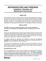
Dimensions
Version Compressor model D(mm) H(mm) H1(mm) H2(mm) L1(mm) L2(mm) Outline drawing number
Single VLZ028-035-044 164.5 404.4 230.5 360.4 190.5 190.5 0VG8213B
Single compressors
Single version
Ø164.5
Suction line
3/4"
Organ pipe
tting
Schrader valve
and cover
Overall height:
Top of sensor bracket
404.4
360.4
230.5
55.0
42.5
78.0
11
239
190.5
Ø19.5
4X
(95.25)
129.5
109.7
Suction line
111.3
discharge line
14°±2°
45°±2°
(31°)
(17°)
(34°)
(60°)
Oil level sensor
prism
Discharge line
1/2"
ØD
H2
H1
L1
L2
Earth grounding
EMC bracket to
terminations of
shielded wire
Mounting GrommetTerminal box (quick connect spade terminals)
Ø 41
29.5
Recommended torque for
mounting bolts: 11 Nm (±1 Nm)
Ø11
9FRCC.PC.052.A2.02

GENERAL INFORMATIONSYSTEM DESIGNINTEGRATION INTO SYSTEMORDERING INFORMATION PRODUCT INFORMATION
Dimensions
Connection Details
VLZ028-035-044 single version
Suction connection Brazed 3/4"
Discharge connection Brazed 1/2"
Oil sight glass Threaded (1"1/8 – 18 UNF)
Oil equalization connection -
Shrader Male 1/4" Flare incorporating a Schrader valve
1) VLZ compressors single versions come
equipped with a threaded oil sight glass with
1"1/8 – 18 UNEF connection. It can be used for
a visual check of oil amount and condition.
2) Schrader: The oil ll connection and
gauge port is a 1/4" male are connector
incorporating a Schrader valve.
Compressor models Brazed connection size
Rotolock adaptor set
(adaptor, gasket, sleeve, nut)
Rotolock adaptor
( adaptor only)
Rotolock Solder sleeve ODF Code Number Code Number
VLZ028-035-044
Suction 3/4" 1-1/4" 3/4"
120Z0126
120Z0366
Discharge 1/2" 1" 1/2" 120Z0365
VLZ compressors are all delivered with suction
and discharge brazed connections only. They are
copper-plated steel connections.
Rotolock adaptors are available, refer to the
information above.
10 FRCC.PC.052.A2.02

GENERAL INFORMATIONSYSTEM DESIGNINTEGRATION INTO SYSTEMORDERING INFORMATION PRODUCT INFORMATION
Dimensions
CDS803 Frequency
converter
L
H
W
Min 100
Clearance above for cooling
Min 100
Clearance above for cooling
Frequency converter dimensions depend on
supply voltage and power. The table below
gives an overview of the overall dimensions and
dierent drive enclosures (H3-H4). Details for
each drive enclosure are on the following pages.
Drive supply voltage
Drive power
kW
Compressor
voltage code
Compressor
model
IP20
Drive enclosure
Overall drive size
(H x W x L) mm
Overall drive size
(H x W x L) mm
incl. decoupling
plate
Clearance above/
below
(mm/inch)
T2: 200-240/3/50-60 7.5 J VLZ028-035-044 H4 296x135x241 359x135x241 100/4
T4: 380-480/3/50-60 7.5 G VLZ028-035-044 H3 255x100x206 329x100x206 100/4
CDS803 frequency converter
A
a
b
B
C
D
e
f
a
e
Enclosure Height (mm) Width (mm) Depth (mm) Mounting hole (mm) Max. Weight
Frame IP Class A A
1)
a B b C d e f kg
H3 IP20 255 329 240 100 74 206 11 5.5 8.1 4.5
H4 IP20 296 359 275 135 105 241 12.6 7 8.4 7.9
A
1)
Including decoupling plate.
The dimensions are only for the physical units, but when installing in an application it is necessary to add space for free air passage both above and below the units. The amount
of space for free air passage is listed in “frequency converter dimensions - Clearance above/below (mm/inch)”.
99 99
Decoupling Plate Illustration
Decoupling Plate
11FRCC.PC.052.A2.02

GENERAL INFORMATIONSYSTEM DESIGNINTEGRATION INTO SYSTEMORDERING INFORMATION PRODUCT INFORMATION
Electrical data, connections and wiring
Compressor electrical
specications
Compressor rated
voltage (V)
Model
RW(Ω) at 20°C line
to line
RLA (A)
Max Operating
Current (A)
400 VLZ044
0.708Ω±7%
10.5 12.1
400 VLZ035 8.5 9.8
400 VLZ028 7 8.1
208 VLZ044
0.185Ω±7%
22.1 25.4
208 VLZ035 19.7 22.7
208 VLZ028 14.6 16.8
RW: Winding resistance per winding, measured at motor terminals
RLA: Rated load Amp
Because VLZ compressors are powered by a
frequency converter, the mains frequency, 50 or
60 Hz, is no longer an issue. Only the mains
voltage is to be taken into account. With 2 motor
voltage codes, the most common mains voltages
and frequencies are covered. VLZ compressors
will only work normally when connect to a
frequency converter. Connect VLZ compressors
to the mains power supply directly will cause
compressor motor get burnt.
Supply voltage
Voltage code Mains voltage range of drive
J
200-240V / 3ph / 50Hz &
200-240V / 3ph / 60Hz (±10%)
G
380-480V / 3ph / 50Hz &
380-480V / 3ph / 60Hz (±10%)
Rated Load Amp value is the current value at
maximum load, in the operating envelope, and at
maximum speed and rated drive input voltage.RLA (Rated Load Amp)
MOC (Max Operating
Current)
Wiring connections
Max operating current is the maximum
continuous current which is 115% of RLA. This
value is printed on compressor nameplate.
VLZ scroll compressors will only compress gas
while rotating counter-clockwise (when viewed
from the top of the compressor).
The drawing shows electrical terminal labeling
and should be used as a reference when wiring
the compressor.
U, V & W of the drive and the compressor must be
connected accordingly.
For use of EMC bracket with shielded cable, it is
recommended to have a thread cutting screw
(#10-32) having a torque of 3NM.
Terminal cover mounting The terminal cover and gasket should be installed
prior to operation of the compressor. The terminal
cover has two outside tabs, 180 degrees apart,
that engage the terminal fence. When installing
the cover, check that it is not pinching the lead
wires.
Terminal cover removal
push
push
push
Earth
grounding
EMC bracket to
terminations of
shielded wire
12 FRCC.PC.052.A2.02

GENERAL INFORMATIONSYSTEM DESIGNINTEGRATION INTO SYSTEMORDERING INFORMATION PRODUCT INFORMATION
Electrical data, connections and wiring
Fuses Danfoss recommends using the fuses listed
below to protect service personnel and property
in case of component break-down in the
frequency converter.
For circuit breakers, Moeller types have been
tested and are recommended. Other types of
circuit breakers may be used provided they limit
the energy to a level equal to or lower than the
Moeller types.
Wire sizes Below table lists recommended wiring sizes for the motor compressor power supply cables. These
wiring sizes are valid for a cable length up to 20m.
from network
to drive
from drive to
to compressor
CDS 803
UL Compliant fuses Recommended circuit breaker
UL Non UL IP20
Bussmann Bussmann Bussmann Bussmann Max fuse
Type RK5 Type RK1 Type J Type T Type G Moeller type
3x200-240 V IP20
VLZ028-035-044 FRS-R-50 KTN-R50 JKS-50 JJN-50 50 PKZM4-50
3x380-480 V IP20
VLZ028-035-044 FRS-R-25 KTS-R25 JKS-25 JJS-25 25 PKZM4-25
From network to frequency converter From frequency converter to compressor
Type mm² AWG Type mm² AWG
200 - 240 V CDS803-7.5kW(IP20) 6 10 VLZ028/035/044-J 6 10
380 - 400 V CDS803-7.5kW(IP20) 4 10 VLZ028/035/044-G 4 10
Note: The wire size here is the guidelines but not the actual needed cable. The needed cable size should be specied by the OEM
depending on the unit design, ambient temperature, the wire material, current, etc...
13FRCC.PC.052.A2.02

GENERAL INFORMATIONSYSTEM DESIGNINTEGRATION INTO SYSTEMORDERING INFORMATION PRODUCT INFORMATION
Electrical data, connections and wiring
Wiring & EMC protection The motor compressor power supply from
the CDS803 frequency converter to the VLZ
compressor must be done with a braided
screened / armored cable. This cable needs to
have its screen / armor conduit connected to
earth on both ends. Avoid terminating this cable
connection with twisting ends (pigtails) because
that would result in an antenna phenomena and
decrease the eectiveness of the cable.
Control cables to the CDS803 frequency
converter must use the same installation
principles as the power supply cable.
The motor compressor cable must be installed in
a conduit separated from the control and mains
cables.
Physical installation of the frequency converter
on the mounting plate must ensure good
electrical contact between the mounting plate
and the metal chassis of the converter. Use star-
washers and galvanically conductive installation
plates to secure good electrical connections.
Refer to instructions MG18N102 for tightening
torques and screw sizes.
Note that the CDS803 must be mounted on a
plain wall to ensure a good air ow through its
heat exchanger.
The CDS803 frequency converter generates by
design a compressor soft start with an default
initial ramp up of 7.5s to 50 rps.
Current inrush will not exceed the frequency
converter maximum current.
Basically seen from the mains the inrush peak
reach a level which is only a few percent more
than the rated nominal current.
Soft-start control
The compressor will only operate properly in a
single direction. If electrical connections are done
correctly between the drive and the compressor
terminals (compressor and drive terminals U, V &
W matching), the drive will provide correct phase
supply to the compressor, and reverse rotation
will be not possible:
• CDS terminal U (96) to VLZ terminal T1/U
• CDS terminal V (97) to VLZ terminal T2/V
• CDS terminal W (98) to VLZ terminal T3/W
If compressor and drive U, V & W terminals are
not matching, the compressor can operate in a
reverse rotation. This results in excessive noise,
no pressure dierential between suction and
discharge, and suction line warming rather than
immediate cooling. The compressor can be
rapidly damaged in these conditions. To protect
compressors from reverse rotation, below action
is recommended:
- Use pressure sensors to monitor pressure
dierence between discharge and suction of
the compressor, and for normal operation,
discharge pressure should be at least 1 bar
higher than suction pressure within 30 s
running after compressor starting.
Mains connection to the CDS frequency
converter order has no inuence on the output
phase sequence which is managed by the
frequency converter.
Phase sequence and
reverse rotation
protection
14 FRCC.PC.052.A2.02

GENERAL INFORMATIONSYSTEM DESIGNINTEGRATION INTO SYSTEMORDERING INFORMATION PRODUCT INFORMATION
Electrical data, connections and wiring
The compressor terminal box IP rating according to IEC529 is IP22.IP rating
Element Numerals or letters Meaning for the protection of equipment
First characteristic
numeral
0
1
2
3
4
5
6
Against ingress of solid foreign objects
(non protected)
≥ 50 mm diameter
≥ 12.6 mm diameter
≥ 2.5 mm diameter
≥ 1.0 mm diameter
dust protected
dust tight
Second
characteristic
numeral
0
1
2
3
4
5
6
7
8
Agains ingress of water with harmful effects
(non protected
vertically dripping
dripping (15° tilted)
spaying
splashing
jetting
powerful jetting
temporary immersion
continuous immersion
VLZ scroll compressors are not equipped with
an internal motor protector. Motor protection
is provided by the variable speed drive. All
parameters are factory preset in order to
guaranty locked rotor or overload current
protection.
When a warning situation is reached in the
current control, the CDS frequency converter
will automatically reduce the compressor
speed in order to keep the motor current of the
compressor below the maximum allowed.
Motor protection
The maximum allowable voltage imbalance
between each phase is 3%. Voltage imbalance
causes high amperage over one or several
phases, which in turn leads to overheating and
possible drive damage.
Mains imbalance function in CDS frequency
converter can be set to “[0] Trip” or “[1] Warning”
in 14.12 parameter. It is, by default, factory preset
to “[1] Warning”.
Then the compressor electrical motor is never
aected by main voltage imbalance situations
which are made completely transparent by the
frequency converter.
Voltage imbalance
15FRCC.PC.052.A2.02

GENERAL INFORMATIONSYSTEM DESIGNINTEGRATION INTO SYSTEMORDERING INFORMATION PRODUCT INFORMATION
Approval and certicates
VLZ compressors comply with the following approvals and certicates.Approvals and
certicates
Internal free volume
CE
(European Directive)
VLZ code G & code J
UL
(Underwriters Laboratories)
All VLZ models
EMC
2014/30/EU
VLZ code G & code J
CCC VLZ code G
Products Internal free volume at LP side without oil (liter)
VLZ028 3.2
VLZ035 3.2
VLZ044 3.2
Conformity to directives Pressure equipment directive 2014/68/EU
Machinery directive 2006/42/EC annex II b
Low voltage directive 2014/35/EU
Electromagnetic compatibility 2014/30/EU
Products VLZ028-035-044
Refrigerating uids Group 2
Category PED I
Evaluation module no scope
Service temperature - Ts -35°C < Ts < 55°c
Service pressure (low side) - Ps 26.17 bar(g)
Declaration of conformity contact Danfoss
Marking of conformity CE
16 FRCC.PC.052.A2.02

GENERAL INFORMATIONPRODUCT INFORMATIONINTEGRATION INTO SYSTEMORDERING INFORMATION SYSTEM DESIGN
Design piping
General requirements Proper piping practices should be employed to:
1. Ensure adequate oil return, even under
minimum load conditions (refrigerant speed,
piping slopes…). For more details see section
“Manage oil in the circuit”.
2. Avoid condensed liquid refrigerant from
draining back to the compressor when stopped
(discharge piping upper loop). For more details
see section “Manage o cycle migration”.
General recommendations are described in the
gures below:
3. Piping should be designed with adequate
three-dimensional exibility to avoid excess
vibration. It should not be in contact with the
surrounding structure, unless a proper tubing
mount has been installed. For more information
on noise and vibration, see section on: “Sound
and vibration management”.
4. The design in this guideline is for short circuit
application. However, for long circuit and split
system application, an oil separator and an
external non-return valve are mandatory to use.
HP
4 m/s or more
0.5% slope
To condenser
max. 4 m
max. 4 m
0.5% slope
U-trap,
as short as possible
4m/s or more
U trap, as short as possible
Evaporator
LP
8 to 12 m/s
HP
LP
Condenser
3D exibility
Upper loop
17FRCC.PC.052.A2.02

GENERAL INFORMATIONPRODUCT INFORMATIONINTEGRATION INTO SYSTEMORDERING INFORMATION SYSTEM DESIGN
Ø 41
29.5
1.7
Recommended torque for
mounting bolts: 11 Nm (±1 Nm)
41
Ø11
5/16" - 18 UNC
self tapping
Design compressor mounting
General requirements
Single requirements
Compressors used in single applications must be
mounted with exible grommets.
During operation, the maximum inclination from
the vertical plane must not exceed 7 degrees.
All compressors are delivered with four rubber
grommets and metal sleeves. Compressors
must always be mounted with these grommets.
Recommended torque for mounting bolts: 11 Nm
(±1 Nm).
18 FRCC.PC.052.A2.02

GENERAL INFORMATIONPRODUCT INFORMATIONINTEGRATION INTO SYSTEMORDERING INFORMATION SYSTEM DESIGN
Purpose Test condition Pass criteria Solutions
Check proper oil return
Lowest foreseeable evaporation,
and highest foreseeable
condensation.
Minimum speed during 6 hours.
Oil level must be visible or full in the
sight glass when the compressor is
running.
1. Top-up with oil, generally 3% of
the total system refrigerant charge
(in weight). Above 3% look for
potential oil trap in the system.
2. Adjust oil boost function, for more
details see section”Oil management
logic”.
3. Oil separator* can be added
A
Manage oil in the circuit
R
Requirement
System evaluation
Test, criteria and solutions
Oil level must be visible or full in the sight
glass when the compressor is running and when
all compressors of the circuit are stopped.
Single compressor
Non split Oil return test described below
Split
1. Since each installation is unique, test can not validate
the oil return, Oil separator* is mandatory
2. Pay special attention to “Piping design” on eld
3. Oil level must be checked and adjusted at
commissioning.
*Oil separator
Oil separator which has the internal
reintegration system is recommended, such as
oating ball oil separator.
Oil return injection must be done in suction
line and not in oil sump. If there is a suction
accumulator, place the oil return on suction pipe,
between suction accumulator and compressor
suction port.
In any case, the T° measurement used for
superheat control, (bulb or sensor ) must be
placed before the oil injection.
NRV must be used at outlet of oil separator to
prevent Compressor O Cycle migration issues.
Do not place the oil separator in the air ow, to
avoid having oil separator acting as a condenser.
Oil separator
Check valve
19FRCC.PC.052.A2.02

GENERAL INFORMATIONPRODUCT INFORMATIONINTEGRATION INTO SYSTEMORDERING INFORMATION SYSTEM DESIGN
Manage sound and vibration
Typical sounds and vibrations in systems can be
broken down into the following three categories:
• Sound radiation (through air)
• Mechanical vibrations (through parts and
structure)
• Gas pulsation (through refrigerant)
The following sections focus on the causes and
methods of mitigation for each of the above
sources.
Compressor sound
radiation
For sound radiating from the compressors,
the emission path is air and the sound waves
are travelling directly from the machine in all
directions.
Sound levels are as follows:
• For compressors running alone:
Compressor
model
Frequency RPS
200V 400V
Acoustic hood
code number
Sound power
dB(A)
Attenuation
dBA
Sound power
dB(A)
Attenuation
dBA
VLZ028-035-044
60 82 9 82 9
120Z5083
100 91 9 91 9
Sound power and attenuation are given at ARI conditions, measured in free space
Attenuation given with acoustic hood
Materials are UL approved
During compressor shut down, a short reverse
rotation sound is generated. The duration of this
sound depends on the pressure dierence at shut
down and should be less than 3 seconds.
This phenomenon has no impact on compressor
reliability.
Mitigations methods:
We can consider two means to reduce
compressors sound radiations:
1. Acoustic hoods are quick and easy to install
and do not increase the overall size of the
compressors. Acoustic hoods are available from
Danfoss as accessories. Refer to the table above
for sound levels, attenuation and code numbers.
2. Use of sound-insulation materials on the inside
of unit panels is also an eective means to reduce
radiation.
20 FRCC.PC.052.A2.02
/