Page is loading ...

125135-4
11/00
© 2000 by Crown Audio, Inc., P.O. Box 1000, Elkhart, Indiana 46515-
1000 U.S.A. Telephone: 219-294-8000. The
IQ–P.I.P.–MEM
is
produced by Crown Audio, Inc. Trademark Notice:
MPX-6
™
,
SMX-6
™
,
SmartAmp
™
,
PIP
™
and
Macro Reference
™
are trademarks and
Amcron
®
,
Crown
®
,
IQ System
®
,
IOC
®
,
ODEP
®
,
Macro-Tech
®
,
Com-
Tech
®
and
P.I.P.
®
are registered trademarks of Crown International,
Inc. Other trademarks are the property of their respective owners.
An IQ System
®
Programmable Input Processor
for Crown
®
PIP
™
-compatible Power Amplifiers
Note: The information provided in this manual was deemed accurate as
of the publication date. However, updates to this information may have
occurred. To obtain the latest version of this manual, please visit the
Crown website at www.crownaudio.com.
Obtaining Other Language Versions:
To obtain information in another language about the use of this product,
please contact your local Crown Distributor. If you need assistance lo-
cating your local distributor, please contact Crown at 219-294-8200.
Printed on
recycled paper.

Page 2
Reference Manual
IQ–P.I.P.-MEM Programmable Input Processor for IQ Systems
NORTH AMERICA
SUMMARY OF WARRANTY
The Crown Audio Division of Crown International, Inc., 1718 West Mishawaka Road,
Elkhart, Indiana 46517-4095 U.S.A. warrants to you, the ORIGINAL PURCHASER and
ANY SUBSEQUENT OWNER of each NEW Crown product, for a period of three (3)
years from the date of purchase by the original purchaser (the “warranty period”) that
the new Crown product is free of defects in materials and workmanship. We further
warrant the new Crown product regardless of the reason for failure, except as excluded
in this Warranty.
ITEMS EXCLUDED FROM THIS CROWN WARRANTY
This Crown Warranty is in effect only for failure of a new Crown product which occurred
within the Warranty Period. It does not cover any product which has been damaged
because of any intentional misuse, accident, negligence, or loss which is covered
under any of your insurance contracts. This Crown Warranty also does not extend to
the new Crown product if the serial number has been defaced, altered, or removed.
WHAT THE WARRANTOR WILL DO
We will remedy any defect, regardless of the reason for failure (except as excluded),
by repair, replacement, or refund. We may not elect refund unless you agree, or unless
we are unable to provide replacement, and repair is not practical or cannot be timely
made. If a refund is elected, then you must make the defective or malfunctioning
product available to us free and clear of all liens or other encumbrances. The refund
will be equal to the actual purchase price, not including interest, insurance, closing
costs, and other finance charges less a reasonable depreciation on the product from
the date of original purchase. Warranty work can only be performed at our authorized
service centers or at the factory. We will remedy the defect and ship the product from
the service center or our factory within a reasonable time after receipt of the defective
product at our authorized service center or our factory. All expenses in remedying the
defect, including surface shipping costs in the United States, will be borne by us. (You
must bear the expense of shipping the product between any foreign country and the
port of entry in the United States and all taxes, duties, and other customs fees for such
foreign shipments.)
HOW TO OBTAIN WARRANTY SERVICE
You must notify us of your need for warranty service not later than ninety (90) days after
expiration of the warranty period. All components must be shipped in a factory pack,
which, if needed, may be obtained from us free of charge. Corrective action will be
taken within a reasonable time of the date of receipt of the defective product by us or
our authorized service center. If the repairs made by us or our authorized service
center are not satisfactory, notify us or our authorized service center immediately.
DISCLAIMER OF CONSEQUENTIAL & INCIDENTAL DAMAGES
YOU ARE NOT ENTITLED TO RECOVER FROM US ANY INCIDENTAL DAMAGES
RESULTING FROM ANY DEFECT IN THE NEW CROWN PRODUCT. THIS INCLUDES
ANY DAMAGE TO ANOTHER PRODUCT OR PRODUCTS RESULTING FROM SUCH
A DEFECT.
SOME STSOME ST
SOME STSOME ST
SOME ST
AA
AA
A
TES DO NOT ALLOW THE EXCLUSION OR LIMITTES DO NOT ALLOW THE EXCLUSION OR LIMIT
TES DO NOT ALLOW THE EXCLUSION OR LIMITTES DO NOT ALLOW THE EXCLUSION OR LIMIT
TES DO NOT ALLOW THE EXCLUSION OR LIMIT
AA
AA
A
TIONS OFTIONS OF
TIONS OFTIONS OF
TIONS OF
INCIDENTINCIDENT
INCIDENTINCIDENT
INCIDENT
AL OR CONSEQUENTIAL DAMAGES, SO THE ABOVE LIMITAL OR CONSEQUENTIAL DAMAGES, SO THE ABOVE LIMIT
AL OR CONSEQUENTIAL DAMAGES, SO THE ABOVE LIMITAL OR CONSEQUENTIAL DAMAGES, SO THE ABOVE LIMIT
AL OR CONSEQUENTIAL DAMAGES, SO THE ABOVE LIMIT
AA
AA
A
TION ORTION OR
TION ORTION OR
TION OR
EXCLUSION MAEXCLUSION MA
EXCLUSION MAEXCLUSION MA
EXCLUSION MA
Y NOT APPLY NOT APPL
Y NOT APPLY NOT APPL
Y NOT APPL
Y TO YOU.Y TO YOU.
Y TO YOU.Y TO YOU.
Y TO YOU.
WARRANTY ALTERATIONS
No person has the authority to enlarge, amend, or modify this Crown Warranty. This
Crown Warranty is not extended by the length of time which you are deprived of the use
of the new Crown product. Repairs and replacement parts provided under the terms
of this Crown Warranty shall carry only the unexpired portion of this Crown Warranty.
DESIGN CHANGES
We reserve the right to change the design of any product from time to time without
notice and with no obligation to make corresponding changes in products previously
manufactured.
LEGAL REMEDIES OF PURCHASER
THIS CROWN WARRANTY GIVES YOU SPECIFIC LEGAL RIGHTS, YOU MAY ALSO
HAVE OTHER RIGHTS WHICH VARY FROM STATE TO STATE. No action to enforce this
Crown Warranty shall be commenced later than ninety (90) days after expiration of the
warranty period.
THIS STATEMENT OF WARRANTY SUPERSEDES ANY OTHERS
CONTAINED IN THIS MANUAL FOR CROWN PRODUCTS.
9/90
Y
E
A
R
3
THREE YEAR
FULL WARRANTY

Page 3
Reference Manual
IQ–P.I.P.-MEM Programmable Input Processor for IQ Systems
WORLDWIDE
SUMMARY OF WARRANTY
The Crown Audio Division of Crown International, Inc., 1718 West Mishawaka Road,
Elkhart, Indiana 46517-4095 U.S.A. warrants to you, the ORIGINAL PURCHASER and
ANY SUBSEQUENT OWNER of each NEW Crown
1
product, for a period of three (3)
years from the date of purchase by the original purchaser (the “warranty period”) that
the new Crown product is free of defects in materials and workmanship, and we further
warrant the new Crown product regardless of the reason for failure, except as excluded
in this Crown Warranty.
1
Note: If your unit bears the name “Amcron,” please substitute it for the name “Crown”
in this warranty.
ITEMS EXCLUDED FROM THIS CROWN WARRANTY
This Crown Warranty is in effect only for failure of a new Crown product which occurred
within the Warranty Period. It does not cover any product which has been damaged
because of any intentional misuse, accident, negligence, or loss which is covered
under any of your insurance contracts. This Crown Warranty also does not extend to
the new Crown product if the serial number has been defaced, altered, or removed.
WHAT THE WARRANTOR WILL DO
We will remedy any defect, regardless of the reason for failure (except as excluded),
by repair, replacement, or refund. We may not elect refund unless you agree, or unless
we are unable to provide replacement, and repair is not practical or cannot be timely
made. If a refund is elected, then you must make the defective or malfunctioning
product available to us free and clear of all liens or other encumbrances. The refund
will be equal to the actual purchase price, not including interest, insurance, closing
costs, and other finance charges less a reasonable depreciation on the product from
the date of original purchase. Warranty work can only be performed at our authorized
service centers. We will remedy the defect and ship the product from the service center
within a reasonable time after receipt of the defective product at our authorized service
center.
HOW TO OBTAIN WARRANTY SERVICE
You must notify us of your need for warranty service not later than ninety (90) days after
expiration of the warranty period. All components must be shipped in a factory pack.
Corrective action will be taken within a reasonable time of the date of receipt of the
defective product by our authorized service center. If the repairs made by our
authorized service center are not satisfactory, notify our authorized service center
immediately.
DISCLAIMER OF CONSEQUENTIAL & INCIDENTAL DAMAGES
YOU ARE NOT ENTITLED TO RECOVER FROM US ANY INCIDENTAL DAMAGES
RESULTING FROM ANY DEFECT IN THE NEW CROWN PRODUCT. THIS INCLUDES
ANY DAMAGE TO ANOTHER PRODUCT OR PRODUCTS RESULTING FROM SUCH
A DEFECT.
WARRANTY ALTERATIONS
No person has the authority to enlarge, amend, or modify this Crown Warranty. This
Crown Warranty is not extended by the length of time which you are deprived of the use
of the new Crown product. Repairs and replacement parts provided under the terms
of this Crown Warranty shall carry only the unexpired portion of this Crown Warranty.
DESIGN CHANGES
We reserve the right to change the design of any product from time to time without
notice and with no obligation to make corresponding changes in products previously
manufactured.
LEGAL REMEDIES OF PURCHASER
No action to enforce this Crown Warranty shall be commenced later than ninety (90)
days after expiration of the warranty period.
THIS STATEMENT OF WARRANTY SUPERSEDES ANY OTHERS
CONTAINED IN THIS MANUAL FOR CROWN PRODUCTS.
9/90
THREE YEAR
FULL WARRANTY
Y
E
A
R
3

Page 4
Reference Manual
IQ–P.I.P.-MEM Programmable Input Processor for IQ Systems
Important Safety Instructions
1) Read these instructions.
2) Keep these instructions.
3) Heed all warnings.
4) Follow all instructions.
5) Do not use this apparatus near water.
6) Clean only with a dry cloth.
7) Do not block any ventilation openings. Install in accor-
dance with the manufacturer’s instructions.
8) Do not install near any heat sources such as radiators,
heat registers, stoves, or other apparatus that produce
heat.
9) Do not defeat the safety purpose of the polarized or
grounding-type plug. A polarized plug has two blades
with one wider than the other. A grounding-type plug has
two blades and a third grounding prong. The wide blade
or the third prong is provided for your safety. If the
provided plug does not fit into your outlet, consult an
electrician for replacement of the obsolete outlet.
10) Protect the power cord from being walked on or pinched,
particularly at plugs, convenience receptacles, and the
point where they exit from the apparatus.
11) Only use attachments/accessories specified by the
manufacturer.
12) Use only with a cart, stand, bracket, or table specified by
the manufacturer, or sold with the apparatus. When a cart
is used, use caution when moving the cart/apparatus
combination to avoid injury from tip-over.
13) Unplug this apparatus during lightning storms or when
unused for long periods of time.
14) Refer all servicing to qualified service personnel. Servic-
ing is required when the apparatus has been damaged in
any way, such as power-supply cord or plug is damaged,
liquid has been spilled or objects have fallen into the
apparatus, the apparatus has been exposed to rain or
moisture, does not operate normally, or has been
dropped.
15) To reduce the risk of fire or electric shock, do not expose
this apparatus to rain or moisture.

Page 5
Reference Manual
IQ–P.I.P.-MEM Programmable Input Processor for IQ Systems
Quick Install Procedure
This procedure is provided for those who are already familiar with Crown’s IQ System and
who would like to install the IQ–P.I.P.-MEM in the shortest time possible. Less experienced
installers or those wishing a full explanation of the installation procedure are encouraged to
go to Section 4 where the full installation procedure is described.
Prepare the IQ–P.I.P.-MEM:
1. Set the IQ address switch SW1 (see Figures 4.1 and 4.2) on the IQ–P.I.P.-MEM to
an unused IQ address. (Tip: Record the IQ address on the small blank label that is
provided on lower right corner of the PIP
™
panel.)
2. Set the input switches S1 and S2 (see Figures 4.3 and 4.4) for the desired input gain
and, if a microphone input is desired, phantom power. (Tip: Record the input setting
on the small blank label that is provided on lower right corner of the PIP panel.)
3. Set jumpers JP4 and JP5. Set both jumpers JP4 and JP5 to the “OUT” position if
either a PIP2-compatible amplifier (such as the Com-Tech10 Series or Macro-Tech
02 Series) will be used. Both JP4 and JP5 should be set to the “IN” position for all
other amplifiers.
Prepare the amplifier:
4. Turn down the level controls of the amplifier and turn off the amplifier.
5. Unplug the power cord of the amplifier from the AC mains.
6. Remove the existing PIP or cover panel from the amplifier back panel (two screws).
7. Set the amplifier input sensitivity switch to 0.775 V. (See the Reference or Owner’s
Manual of the amplifier.)
Install the IQ–P.I.P.-MEM into the amplifier:
8. Carefully ground yourself to the chassis of the amplifier before installing the IQ–
P.I.P.-MEM. It is a good idea to maintain ground contact between yourself and the
amplifier while inserting the module into the PIP card rails in the next step.
9. Install the
IQ–P.I.P.-MEM into the amplifier:
Standard PIP Amplifiers:
Align the edges of the IQ–P.I.P.-MEM in the PIP card rails
and firmly push the unit in until it seats against the mounting bracket (see Figure
4.5).
PIP2 Compatible Amplifiers:
Connect the PIP2 input adapter to the amplifier input
cables. Plug the IQ–P.I.P.-MEM into the PIP2 input adapter and insert the assembly
into the PIP opening in the back of the amplifier (see Figure 4.6 and 4.7).
10. Tighten the two PIP mounting screws until it is secured to the amplifier back panel.
Install the wiring:
11. Connect the IQ–P.I.P.-MEM to the IQ System via the Crown Bus (see Section 4.6 if
more information is needed).
12. Connect the audio signal wiring to the IQ–P.I.P.-MEM (see Section 4.7 if more infor-
mation is needed).
13. Connect the amplifier back to the AC receptacle.
Adjust the levels and scale factors:
14. Turn the level controls of the amplifier to their full setting. Use the software-con-
trolled input attenuators on the IQ–P.I.P.-MEM to adjust the input levels down.
15.
Standard PIP Amplifiers:
Manually configure the scaling factors of the IQ–P.I.P.-
MEM with appropriate IQ System software.
PIP2 Compatible Amplifiers:
The scaling factors will be automatically set.

Page 6
Reference Manual
IQ–P.I.P.-MEM Programmable Input Processor for IQ Systems
The information furnished in this manual does not include all of the details
of design, production, or variations of the equipment. Nor does it cover
every possible situation which may arise during installation, operation or
maintenance. If you need special assistance beyond the scope of this
manual, please contact our Technical Support Group.
Crown Technical Support Group
Plant 2 SW, 1718 W. Mishawaka Rd., Elkhart, Indiana 46517 U.S.A.
Phone: 800-342-6939 (North America, Puerto Rico and Virgin Islands)
or 219-294-8200
Fax: 219-294-8301 Internet: http://www.crownaudio.com
WARNING
TO REDUCE THE RISK OF ELECTRIC
SHOCK, DO NOT EXPOSE THIS
EQUIPMENT TO RAIN OR MOISTURE!
FCC COMPLIANCE NOTICE
This equipment has been tested and found to
comply with the limits for a Class A digital Device,
pursuant to Part 15 of the FCC Rules. These limits are
designed to provide reasonable protection against
harmful interference when the equipment is
operated in a commercial environment. This
equipment generates, uses and can radiate radio
frequency energy and, if not installed and used in
accordance with the instruction manual, may cause
harmful interference to radio communications.
Operation of this equipment in a residential area is
likely to cause harmful interference in which case the
user will be required to correct the interference at his
own expense.
“The user is cautioned that any changes or
modifications not expressly approved by Crown
International could void the user’s authority to
operate the equipment.”

Page 7
Reference Manual
IQ–P.I.P.-MEM Programmable Input Processor for IQ Systems
Quick Install Procedure ....................................................... 5
1 Welcome ................................................................................ 9
1.1 Unpacking ................................................................... 9
2 Facilities ................................................................................. 10
3 Features ................................................................................. 13
3.1 Amplifier Information ................................................... 13
3.2 Amp Mode ................................................................... 13
3.3 Power Control .............................................................. 13
3.4 Input Signal Level Monitor .......................................... 13
3.5 Signal Mute.................................................................. 13
3.6 Polarity Inverter ........................................................... 13
3.7 Input Signal Attenuator ............................................... 13
3.8 Output Signal Level Monitor ....................................... 13
3.9 IOC Event Monitor ....................................................... 14
3.10 ODEP Level Monitor .................................................... 14
3.11 Crown Bus “Drop Out” Relays .................................... 14
3.12 DSPI ............................................................................. 14
3.13 AUX Output ................................................................. 14
3.14 Memory Backup .......................................................... 15
3.15 Reset............................................................................ 15
3.16 User Default Settings .................................................. 15
4 Installation ............................................................................. 16
4.1 Prepare the IQ–P.I.P.-MEM .......................................... 16
4.2 Prepare the Amplifier .................................................. 19
4.3 Install the IQ–P.I.P.-MEM into the Amplifier ................. 19
4.4 Install the Wiring.......................................................... 20
4.5 Adjust the Levels & Scale Factors.............................. 20
4.6 A Closer Look at Crown Bus Wiring ........................... 21
4.7 A Closer Look at Audio Signal Wiring ........................ 26
4.8 Using the AUX Connector ........................................... 27
4.8.1 AUX Output ................................................................. 27
4.8.2 AUX Input .................................................................... 28
CONTENTS

Page 8
Reference Manual
IQ–P.I.P.-MEM Programmable Input Processor for IQ Systems
Contents continued...
ILLUSTRATIONS
1.1 IQ–P.I.P.-MEM .............................................................................. 9
2.1 The IQ–P.I.P.-MEM Facilities ...................................................... 10
4.1 IQ Address Switch (SW1) Location ........................................... 16
4.2 IQ Address Switch (SW1) Values .............................................. 17
4.3 Input Switch (S1, S2) Location .................................................. 18
4.4 Input Switch (S1, S2) Settings ................................................... 18
4.5 Installation into a Standard PIP Amplifier .................................. 19
4.6 PIP2 Input Adapter Connection ................................................. 19
4.7 Installation into a PIP2 Amplifier ................................................ 20
4.8 Amp Scale Factor Values and Output Signal Pad Settings...... 21
4.9 IQ–P.I.P.-MEM Output to IQ Component with DIN ................... 23
4.10 IQ–P.I.P.-MEM Output to IQ Comp. w/ Screw Term. Plug........ 23
4.11 IQ–P.I.P.-MEM Output to IQ Component w/ RJ45 Connector .. 24
4.12 IQ Component w/ Screw Term. Plug to IQ–P.I.P.-MEM Input .. 24
4.13 IQ Component w/ RJ45 Connector to IQ–P.I.P.-MEM Input ..... 24
4.14 Standard Crown Bus Wiring "Loops" to each IQ Component .. 25
4.15 Audio Input Wiring ..................................................................... 26
4.16 The Internal AUX Circuit ............................................................ 27
4.17 A Sample AUX Output Circuit .................................................... 27
5.1 IQ–P.I.P.-MEM Circuit Block Diagram ....................................... 30
7.1 IQ Address Switch (SW1) Settings from 0 to 125 ..................... 33
7.2 IQ Address Switch (SW1) Settings from 126 to 250 ................. 34
5 Technical Information........................................................... 28
5.1 Audio Signals .............................................................. 28
5.2 Amplifier Monitoring: “Monitor Inputs” ....................... 29
5.3 Amplifier Control ......................................................... 29
5.4 IQ System Communications ....................................... 29
5.5 Microprocessor and Reset Switch .............................. 29
6 Specifications ....................................................................... 31
7IQ Address Tables ................................................................. 33
8 Service ................................................................................... 35

Page 9
Reference Manual
IQ–P.I.P.-MEM Programmable Input Processor for IQ Systems
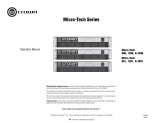
Fig. 1.1 IQ–P.I.P.-MEM
1 Welcome
The I
Q–P.I.P.-MEM
brings powerful
monitor and control capabilities to
your Crown PIP™ (programmable in-
put processor) and PIP2-compatible
amplifiers.
An IQ2-series component, the IQ–
P.I.P.-MEM support Crown’s UCODE
protocol and requires an IQ System
®
with an IQ2-compatible IQ Interface
(such as IQ-INT V2.00). UCODE
(universal code) enables users and
third parties to develop custom soft-
ware objects to control and monitor
IQ2-compatible components like the
IQ–P.I.P.-MEM.
The IQ–P.I.P.-MEM connects the am-
plifier to the Crown Bus of an IQ Sys-
tem so the amplifier can be con-
trolled and monitored. It is powered
by the amplifier and includes a
microprocesser with a memory
backup feature that enables the am-
plifier to resume operation with all of
its IQ settings in tact after a power
outage.
This manual will help you success-
fully install your unit. We strongly rec-
ommend that you read all the in-
structions, warnings and cautions
contained within. Also for your pro-
tection, please send in the warranty
registration card today and save the
bill of sale since it is your official
proof of purchase.
1.1 Unpacking
The unit is shipped in a protective
antistatic bag.
CAUTION: STATIC ELECTRICITY
MAY DAMAGE THE UNIT. Use
caution when handling the unit.
Carefully ground yourself BEFORE
touching the unit. For added safety,
touch the outer metal collar of either
Crown Bus connector.
Avoid unnecessarily touching the
components, edge connector or
solder pads on the circuit boards.
Please unpack and inspect the unit
for any damage that may have
occurred during transit. If damage is
found, notify the transportation
company immediately. Only you, the
consignee, may initiate a claim with
the carrier for shipping damage.
Crown will be happy to cooperate
fully as needed. Save the shipping
carton as evidence of damage for the
shipper’s inspection.
Even if the unit arrived in perfect
condition, as most do, save all
packing materials.
NEVER SHIP THE UNIT WITHOUT
THE FACTORY PACK.

Page 10
Reference Manual
IQ–P.I.P.-MEM Programmable Input Processor for IQ Systems
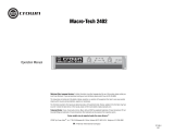
Front View
2 Facilities
A. Mounting Screws
The IQ–P.I.P.-MEM is secured to the
back panel of the amplifier with two
phillips-head screws and star-tooth
lock washers. The lock washers are
required for proper ground connec-
tion.
Fig. 2.1 The IQ–P.I.P.-MEM Facilities
Bottom View
B. Balanced Audio Inputs
A 3-pin female XLR connector is
provided for balanced audio input
to each channel of the amplifier. Pin
1 is chassis (gnd); pin 2 is not in-
verted (+); and pin 3 is inverted (–).
Do not use the Ch.2 input if the am-
plifier is configured in either Bridge
or Parallel-Mono mode.

Page 11
Reference Manual
IQ–P.I.P.-MEM Programmable Input Processor for IQ Systems
C. Reset Switch
A multifunction reset switch is pro-
vided to restore the IQ–P.I.P.-MEM
to a prior state. It can be de-
pressed with a straightened paper
clip through the small hole in the
PIP panel. Press the reset switch
for less than 2 seconds and all set-
tings, except the amplifier model
scale factors, will be reset with
“user default” parameters and the
DSPI will flash once. (If no “user
default” settings have been stored,
the unit will be reset to the “factory
default” settings described next.)
Press the reset switch for more
than 2 seconds and the same set-
tings will be reset with “factory de-
fault” parameters and the DSPI will
flash twice. After the unit has been
reset to the factory default settings,
it will behave like a standard P.I.P.-
FX until it is reprogrammed by an
IQ System or it is toggled to the
“user default” settings.
D. AUX Connector
A 3-pin male mini XLR connector is
provided to control auxiliary equip-
ment. When the AUX feature is
turned on, +15 VDC is provided
across pin 1 (gnd) and pin 3 (+). A
nominal current of 10 mA is avail-
able. The AUX connector also in-
cludes a high-impedance input that
can sense logic signals.
E. DSPI
The DSPI is a Data Signal Presence
Indicator which flashes whenever a
valid IQ command has been re-
ceived. The indicator can also be
forced to stay on to aid rapid
troubleshooting of the Crown Bus
wiring.
F. Crown Bus Input Connector
A lockable 5-pin female DIN con-
nector is provided for input connec-
tion to the Crown Bus. A mating
Switchcraft 502 series connector
can be ordered from Crown (part C
7776-5). Pin 1 is negative (–), pin 2
is positive (+), and pin 3 is ground
(gnd). Pins 4 and 5 are not used.
G. Crown Bus Output
Connector
A lockable 4-pin female DIN con-
nector is used for output connec-
tion to the Crown Bus. A mating
Switchcraft 502 series connector
can be ordered from Crown (part
C 7777-3). Pin 1 is negative (–) and
pin 2 is positive (+). Pins 3 and 4
are not used.
H. Input Switches (S1, S2)
An 8-section DIP switch is used to
configure each input. These
switches are located on the bottom
circuit board. S1 configures the in-
put of Channel 1 and S2 configures
the input of Channel 2. The
switches activate a microphone
preamp and enable phantom
power. The preamp can be turned
off (0 dB gain) or set to either 20 or
40 dB of gain. See Section 4.1.
I. PIP Edge Connector
The gold-plated edge connector of
the top IQ circuit board inserts into
the PIP connector inside the back
of the amplifier. Use care when in-
stalling a PIP module to be certain
that the edge connector is properly
inserted into the amplifier’s PIP con-
nector.

Page 12
Reference Manual
IQ–P.I.P.-MEM Programmable Input Processor for IQ Systems
J. Amplifier Output Pad
Jumpers (JP4, JP5)
These jumpers enable the circuitry
that pads the output signal feeding
the IQ–P.I.P.-MEM so it can be
properly scaled. Factory default
setting for these jumpers is the
“OUT” position as marked on the
digital circuit board. Switch to the
“IN” position whenever the unit is
installed into a PIP-style amplifier.
K. PIP2 SIP Sockets (RN1,
RN2)
These eight-pin SIP (single in-line
package) resistors are provided
for full PIP2 compatibility. IQ–
P.I.P.-MEM-PIP2 modules (re-
quired for PIP2-compatible ampli-
fiers) should come with the SIP net-
works already installed. The SIP
networks are not required and
should be absent on standard IQ–
P.I.P.-MEM modules.
L. IQ Circuit Board (Top)
The top circuit board contains the
IQ communication circuitry, includ-
ing the IQ address switch (SW1),
amplifier output pad jumpers (JP4,
JP5), PIP2 SIP resistors (RN1, RN2)
and the PIP edge connector.
M. Audio Circuit Board
(Bottom)
The bottom circuit board contains
the audio analog circuitry, includ-
ing the input switches (S1, S2).
N. IQ Address Switch (SW1)
An 8-section DIP switch is used to
set the IQ address of the unit (see
Section 4.1). This switch is located
on the top circuit board. Each IQ
component on a Crown Bus is
given a unique IQ address so it can
be independently controlled and
monitored. Two or more IQ compo-
nents of the same type should
NEVER have the same address on
the same Crown Bus loop.

Page 13
Reference Manual
IQ–P.I.P.-MEM Programmable Input Processor for IQ Systems
3 Features
With an IQ–P.I.P.-MEM module a
Crown amplifier can be monitored
and controlled by an IQ System.
This typically involves a host com-
puter (usually a PC), attached to
the IQ System via an IQ2-compat-
ible IQ interface, running IQ soft-
ware. Please contact your Crown
representative or Crown’s Technical
Support Group if you are unfamiliar
with IQ software.
3.1 Amplifier Information
(PIP2 amplifiers only.) Several items
of information about an amplifier
can be displayed by the IQ soft-
ware. These include the manufac-
turer, model, date code, serial
number and revision level. Which
items are available depends on
both the amplifier and the IQ soft-
ware used.
3.2 Amp Mode
The stereo/mono mode of the
amplifier can be stored into the
unit’s memory so the IQ System is
aware of the amplifier’s stereo/
mono switch setting. Storing this
setting serves as an “electronic
reminder” to the system—however,
the stereo/mono mode can
not be
controlled with this setting. The
modes are Stereo (Dual), Bridge-
Mono and Parallel-Mono. This
software amp mode setting is
controlled by the IQ System.
3.3 Power Control
Each channel’s high-voltage supply
can be independently turned on
and off with the Power control. The
IQ System is used to set this
control.
3.4 Input Signal Level
Monitor
The input signal level of each
channel can be monitored by IQ
software. This monitor feature has
a range from +16 dBu to –40 dBu
in ½ dB steps.
3.5 Signal Mute
The output signal of each channel
can be independently muted by the
IQ System. The function typically
provides 80 dB or more of
attenuation.
3.6 Polarity Inverter
The polarity of the input signal of
eachchannel can be independently
inverted by the IQ System.
3.7 Input Signal Attenuator
An attenuator is available at the
input of each channel to control the
input signal level. These atten-
uators are controll and monitored
by the IQ System. Each input
attenuator has a range from 0 dB to
–80 dB in ½ dB steps. (Zero equals
no attenuation.)
3.8 Output Signal Level
Monitor
The output signal level of each
channel of the amplifier can be
monitored by the IQ System. This
monitor feature has a range from –
40 dB to 0 dB where 0 dB is
referenced to the rated output
voltage of the amplifier model. (This
is assumed to be 70-V or the rated
8 ohm output for Com-Tech
amplifiers or the rated 8 ohm output
voltage for all other amplifiers.)

Page 14
Reference Manual
IQ–P.I.P.-MEM Programmable Input Processor for IQ Systems
The output signal of some
amplifiers must be padded before
the IQ–P.I.P.-MEM can scale them.
This is accomplished by setting
jumpers JP4 and JP5 on the IQ
circuit board to the “IN” position.
Only PIP2-compatible amplifiers do
not require these pads. Set jumpers
JP4 and JP5 to the “OUT” position
for them (see Figure 4.8).
The output signals of all amplifiers
must be scaled in order to
“calibrate” the 0 dB level. (See
Section 4.5.) This is accomplished
with either an amplifier ID code or
a user scale factor. The factory
default setting for this is an
amplifier ID code of “CT-70V” which
assumes that the output level is that
of a Com-Tech amplifier (any
model) with both channels in the
70-V output mode. Note: PIP2-
compatible amplifiers are
automatically scaled by the IQ–
P.I.P.-MEM.
3.9 IOC Event Monitor
The Input/Output Comparator
(IOC
®
) of each channel of the
amplifier can be monitored by the
IQ System. The IOC circuitry acts
as a sensitive distortion meter to
provide you
proof of distortion-free
performance
. If distortion of any
kind equals or exceeds 0.05%, the
IOC circuit will cause an indicator
on the front of the amplifier to flash.
By monitoring these events, the IQ
System can flash an indicator on
the screen of the host computer to
alert a user that distortion is
occurring.
3.10 ODEP Level Monitor
The Output Device Emulation
Protection (ODEP
®
) level of each
channel of the amplifier can be
monitored by the IQ software. This
level represents the percent of
available thermodynamic energy
that is currently being used. When
the ODEP level reaches 100%, the
amplifier cannot produce any more
power and “ODEP limiting” will
begin to limit the drive level to the
output devices, thereby protecting
them from too much stress. (See
the amplifier’s Reference or
Owner’s Manual for more
information about ODEP.)
3.11 Crown Bus “Drop Out”
Relays
“Drop out” relays are provided on
the Crown Bus ports to maintain the
continuity of the IQ communication
loop even if the IQ–P.I.P.-MEM loses
power.
3.12 DSPI
A Data Signal Presence Indicator
(DSPI) is provided on the front
panel. It flashes whenever
commands addressed to the IQ–
P.I.P.-MEM are received. It can be
forced to stay on by IQ software to
assist with troubleshooting of an IQ
System.
3.13 AUX Output
A 3-pin male mini XLR connector is
provided to control auxiliary equip-
ment. When the AUX feature is
turned on, +15 VDC is provided
across pin 1 (gnd) and pin 3 (+). A
nominal current of 10 mA is avail-
able. The
IQ System
is used to con-
trol the AUX output.

Page 15
Reference Manual
IQ–P.I.P.-MEM Programmable Input Processor for IQ Systems
3.14 Memory Backup
A memory backup feature is
provided which can be disabled, if
desired. The factory default setting
is “enabled.” When enabled, it
stores all run-time parameters that
can be controlled by the IQ
software into nonvolatile memory
(EEPROM) at approximately one
second intervals. When disabled,
all run-time parameters are
returned to the factory defaults
whenever the unit loses power.
CAUTION: Be careful to turn on the
memory backup feature if the input
attenuators will be used to set
critical levels. If the memory
backup feature is turned off and the
IQ–P.I.P.-MEM loses power, the
attenuators will be reset to 0 dB,
resulting in the loudest possible
signal.
3.15 Reset
A recessed reset switch, acc-
essible from outside the PIP panel,
enables the IQ–P.I.P.-MEM to be
restored to one of two sets of
default settings. A straightened
paper clip or similar small object is
required to press the reset switch.
Press the reset switch for less than
2 seconds and all settings,
except
the amplifier ID code or user scale
factors, will be reset with “user
default” parameters and the DSPI
will flash once. This feature is only
available if “user default” settings
have been previously established. If
none have, pressing the reset
switch for any length of time will
cause the unit to be reset to the
“factory default” settings as
described below.
Press the reset switch for more than
2 seconds and the same settings
will be reset with “factory default”
parameters and the DSPI will flash
twice. After the unit has been reset
to the factory default settings, it will
behave like a standard P.I.P.-FX
until it is reprogrammed by an IQ
System or it is toggled to the “user
default” settings.
3.16 User Default Settings
The parameters for all functions,
except the amplifier ID code or user
scale factors, can be saved as
“user default” parameters. Then,
pressing the reset switch for less
than 2 seconds will restore all
settings to the “user default” values.
Please consult the documentation
of your IQ software for instructions
on setting the “user default” values.

Page 16
Reference Manual
IQ–P.I.P.-MEM Programmable Input Processor for IQ Systems
4 Installation
Before beginning, please carefully
note:
CAUTION: STATIC ELECTRICITY
MAY DAMAGE THE IQ–P.I.P.-MEM
MODULE. Use caution when
handling the unit. Carefully ground
yourself BEFORE touching the IQ–
P.I.P.-MEM module. For added
safety, touch the outer metal collar
of either Crown Bus connector
(Figure 2.1). This should safely
discharge any static electricity
through the ground plane of the
module. Don’t unnecessarily touch
the components, edge connector or
solder pads on the circuit boards.
NOTE — Amplifier Compatibility
The version of the IQ–P.I.P.-MEM
card you received will vary
depending on whether you
indicated the card will be installed
in a PIP2-compatible amplifier
(such as the Crown Macro-Tech 02
Series or Com-Tech 10 Series
amplifiers). The correct card to
install in a PIP2-compatible
amplifier is the IQ–P.I.P.-MEM-PIP2.
The standard IQ–P.I.P.-MEM should
be ordered for non-PIP2-
compatible amplifiers.
Fig. 4.1 IQ Address Switch (SW1) Location
Should you later wish to change the
amplifier you are using for your IQ–
P.I.P.-MEM installation, it is possible
to alter the card's configuration by
simply removing or installing two
SIPS from the card’s circuit boards
1
.
For instructions on installing or
removing these SIPS, contact
Crown Technical Support.
4.1 Prepare the IQ–P.I.P.-MEM
1. Set the IQ address switch
SW1. By giving each IQ
component a unique ad-
dress, it can be individually
controlled and monitored.
Whenever the IQ System
wants to send a command to
just one IQ component, it
first sends its address and
then the command down the
Crown Bus.
The 8-segment DIP switch
(SW1) shown above is used
to set the IQ address of the
IQ–P.I.P.-MEM. No two IQ
components of the same
type which are connected to
1 IQ–P.I.P.-MEM-PIP2 has SIPS installed; IQ–P.I.P.-MEM has SIPS removed.

Page 17
Reference Manual
IQ–P.I.P.-MEM Programmable Input Processor for IQ Systems
the same Crown Bus Loop
can have the same address.
Suppose, for example, the
IQ System has two Crown
Bus loops and this IQ–P.I.P.-
MEM is installed into loop 1
and given address 77. No
other IQ–P.I.P.-MEM can
have the same address in
loop 1. However, an IQ–
P.I.P.-MEM in loop 2 can
have the same address.
Different IQ components in
the same Crown Bus loop
can have the same address.
For example, both an SMX-6
mixer and an IQ–P.I.P.-MEM
can use address 77 in the
same loop.
A valid IQ address is any
number from 1 to 250. Do
not use a number higher
than 250 since they are re-
served for special use. An
address of “0” (zero) should
never be used except to put
the IQ–P.I.P.-MEM into a
stand-alone mode where it is
invisible to the IQ System
and acts as a “dumb” bal-
anced audio input.
Switch SW1 is located on the
right side on the underside
of the top circuit board (Fig-
ure 4.1). It has eight seg-
ments because it actually
contains eight tiny switches
inside. There is an arrow
printed on the switch along
its left side that points to the
“ON” position and the
switches are numbered
along the bottom (Figure
4.2).
Each of the eight switches in
SW1 has a value which
doubles as the switch num-
ber increases. For example
switch 1 has a value of 1;
switch 2 has a value of 2;
switch 3 has a value of 4;
switch 4 has a value of 8 and
so on.
The address is determined
by adding the values of all
switches which are turned
on. In Figure 4.2 switches 1,
3, 4 and 7 are on. Simply add
the values to find the ad-
dress: 1+4+8+64=77.
A convenient series of IQ
address tables are included
in Section 7. The tables show
the switch settings for all 250
addresses.
2. Set the input switches S1
and S2. Each input can be
configured for either line-
level or microphone-level
signals with an 8-segment
DIP switch. Phantom power
is also available. Switches
S1 and S2 (see Figure 4.3)
are located on the left side
of the lower circuit board.
The table in Figure 4.4 shows
how to set each switch.
Fig. 4.2 IQ Address Switch (SW1)
Values

Page 18
Reference Manual
IQ–P.I.P.-MEM Programmable Input Processor for IQ Systems
IMPORTANT: Two switch
segments (S1, S2) are re-
quired for each setting. Be
careful to use both seg-
ments or improper operation
will result.
Switch S1 configures the in-
put to Channel 1 and switch
S2 configures the input to
Channel 2.
CAUTION: The IQ–P.I.P.-
MEM input preamplifiers
should only be used with
microphone or low-level
signals.
Once the PIP is in-
stalled, there will be no out-
ward indication of the input
preamplifier gain setting.
The protection circuitry of
the amplifier will probably be
activated if the preamplifier
gain is set to 40 dB and a
line-level signal is con-
nected to the input. If your
amplifier appears to “cut
out” when you drive it with a
strong input signal, check to
see if the input preamplifier
gain is set too high.
Recommendations: Attach
a small label to the back of
the PIP to identify whether it
has been set for microphone
or line-level input signals.
And keep the output levels
low if you are uncertain of
the preamplifier settings.
Remember, Crown is
not li-
able for damage due to
overpowering other compo-
nents.
3. Set the jumpers JP4 and
JP5. If the IQ–P.I.P.-MEM is
Fig. 4.3 Input Switch (S1, S2) Location
Fig. 4.4 Input Switch (S1, S2) Settings

Page 19
Reference Manual
IQ–P.I.P.-MEM Programmable Input Processor for IQ Systems
being installed into a PIP2-
compatible amplifier, move
both jumper JP4 and JP5 on
the IQ circuit board to the
“OUT” position (Figures 2.1
and 4.8). Set both JP4 and
JP5 to the “IN” position for
all other amplifiers.
4.2 Prepare the Amplifier
4.
TT
TT
T
urur
urur
ur
n down the level con-n down the level con-
n down the level con-n down the level con-
n down the level con-
trtr
trtr
tr
ols ols
ols ols
ols (full counterclockwise)
and
turtur
turtur
tur
n ofn of
n ofn of
n of
f the amplifierf the amplifier
f the amplifierf the amplifier
f the amplifier.
5.
Disconnect the amplifier’Disconnect the amplifier’
Disconnect the amplifier’Disconnect the amplifier’
Disconnect the amplifier’
ss
ss
s
power corpower cor
power corpower cor
power cor
d.d.
d.d.
d.
6.
Remove the existing PIPRemove the existing PIP
Remove the existing PIPRemove the existing PIP
Remove the existing PIP or
cover panel from the ampli-
fier back panel (two
screws). For PIP2 amplifiers,
this may involve disconnect-
ing the PIP from a PIP2 input
adapter (Figure 4.6). If a
PIP2 input adapter is al-
ready present, do not re-
move the ribbon cables from
the adapter. Otherwise you
will have to reconnect them
in Step 9.
7. Set the amplifier input
sensitivity to 0.775 V. (See
the amplifier’s Reference
Manual.)
4.3 Install the IQ–P.I.P.-MEM
into the Amplifier
8.
CarCar
CarCar
Car
efully grefully gr
efully grefully gr
efully gr
ound yourselfound yourself
ound yourselfound yourself
ound yourself
to the chassis of the ampli-
fier before installing the IQ–
P.I.P.-MEM. It is a good idea
to maintain ground contact
between yourself and the
amplifier while inserting the
module into the PIP card
rails (standard PIP-compat-
Fig. 4.5 Installation into a Standard
PIP Amplifier
Fig. 4.6 PIP2 Input Adapter
Connection
ible amplifiers) or the PIP2
connector (PIP2-compatible
amplifiers).
9. Install the IQ–P.I.P.-MEM
into the amplifier:
Standard PIP Amplifiers:
Align the edges of the IQ–
P.I.P.-MEM in the PIP card
rails and firmly push the unit
in until it is seated against
the mounting bracket (see
Figure 4.5).
PIP2 Amplifiers: Connect the
PIP2 input adapter to the two
input cables of the amplifier
(Figure 4.6). Notice that the
PIP2 input adapter should
be
positioned with the PIP edge
connector on top facing
away from the amplifier. The
20 pin cable (A) is con-
A
B
B
A
18 PIN (B)
20 PIN (A)
P
I
P
2
A
D
A
P
T
E
R
FROM AMPLIFIER

Page 20
Reference Manual
IQ–P.I.P.-MEM Programmable Input Processor for IQ Systems
P
.
I
.
P
.
M
O
D
U
L
E
B
A
C
K
P
A
N
E
L
O
F
P
I
P
2
A
M
P
L
I
F
I
E
R
P
I
P
2
A
D
A
P
T
E
R
Fig. 4.7 Installation into a PIP2
Amplifier
10. Tighten the two PIP mount-
ing screws until the PIP is
secured to the amplifier
back panel.
4.4 Install the Wiring
11. Connect the IQ–P.I.P.-MEM
to the IQ System via the
Crown Bus. See Section 4.6
for full instructions.
12. Connect the audio signal
wiring to the IQ–P.I.P.-MEM.
This includes the XLR input
wiring and, if desired, the
phone jack daisy chain wir-
ing. See Section 4.7 for full
instructions.
13. Reconnect amplifier to the
AC receptacle.
4.5 Adjust the Levels & Scale
Factors
14. Turn the level controls of the
amplifier to their full or maxi-
mum setting. This is required
by the IQ–P.I.P.-MEM. If
needed, use the software-
controlled input attenuators
on the IQ–P.I.P.-MEM to re-
duce the audio levels.
15. Configure the amplifier scale
factors. (Standard PIP-com-
patible amplifiers only—the
scale factors for PIP2-com-
patible amplifiers are set au-
tomatically.) It is necessary
to configure software scale
factors in the microproces-
sor of the IQ–P.I.P.-MEM in
order for it to properly inter-
pret the output signal level of
the amplifier model in which
it is installed. This is easily
done by connecting a host
computer to the IQ–P.I.P.-
MEM via an IQ interface and
the Crown Bus and running
the appropriate software
(see IQ for Windows online
help for more information).
The software will prompt you
for the amplifier model and
send the appropriate scale
factors to the PIP. The scale
factor values are listed in
Figure 4.8 along with the set-
tings of jumpers JP4 and
JP5.
Note: Since it is possible to
configure one channel of a
Com-Tech amplifier in the 8-
Ohm output mode and the
other channel in the 70-Volt
output mode, it may be nec-
essary to configure the scale
factors differently for each
channel.
nected first then the 18 pin
cable (B) is connected. Both
ribbon cables should extend
below the PIP2 input
adapter.
Next, insert the edge con-
nector of the IQ–P.I.P.-MEM
into the PIP2 input adapter
(see Figure 4.7) and insert
the assembly into the PIP
opening in the back of the
amplifier.
/