Klimaire KDIS060-H2G1 Installation guide

Category
Split-system air conditioners
Type
Installation guide
HIGH STATIC PRESSURE DUCT TYPE AIR CONDITIONER
Installation Manual
High Static Pressure Duct Type
IMPORTANT NOTE:
Read this manual carefully before
installing or operating your new air
conditioning unit. Make sure to save
this manual for future reference.
KDIS
Series
Accessories .................................................... 04
Indoor Unit Parts ........................................ 10
Indoor Unit Installation Instructions ....... 11
Safety Precautions ..................................... 06
Outdoor Unit Installation ......................... 17
Outdoor Unit Installation Instructions ...... 17
Outdoor Unit Types and Specifications .... 18
Notes on Drilling Hole in Wall .................... 20
Drainpipe Installation ............................... 21
Table of Contents
Installation Manual
Indoor Unit Installation
........................... 10
Installation Overview ............................... 09
1
2
5
3
4
6
Page 3
Refrigerant Piping Connection....................... 23
Notes on Pipe Length and Elevation ............... 23
Refrigerant Piping Connection Instructions .... 25
Wiring................................................. 27
Outdoor Unit Wiring ................... 27
Indoor Unit Wiring ...................... 28
Power Specifications ................... 30
Air Evacuation ................................................. 32
Evacuation Instructions ................................. 32
Note on Adding Refrigerant ........................
........................
33
Test Run....................................................................................... 34
35
MC MC
7
8
9
10
11
L N
European Disposal Guidelines
Page 4
Accessories
1
The air conditioning system comes with the following accessories. Use all of the installation parts
and accessories to install the air conditioner. Improper installation may result in water leakage,
electrical shock and fire, or cause the equipment to fail.
QUANTITY
SHAPENAME
Soundproof / insulation sheath
2
1
1
1
1
1
Tubing & Fittings
Others
Installation manual
Transfer connector (some models)
(Φ9.52-Φ9.52)/(Φ0.375in-Φ0.375in)
(Packed with the indoor unit )
NOTE: Pipe size may dier from
appliance to appliance. To meet
dierent pipe size requirements,
sometimes the pipe connections
need a transfer connector installed
on the outdoor unit.(some models)
Component of display control
unit (some models)
1
Owner‘s manual
Drain joint (some models)
Seal ring (some models)
Drainpipe Fittings
(for cooling & heating)
1
1
EMC Magnetic
Ring (some
models)
Magnetic ring (wrap the electric
wires S1 & S2 P & Q & E ) around
the magnetic ring twice)
Magnetic ring
(Hitch on the connective cable
between the indoor unit and
outdoor unit after installation.)
S1&S2(P&Q&E)
Optional accessories
There are two types of remote controls: wired and wireless.
Select a remote controller based on customer preferences and requirements and install in an
appropriate place.
Refer to catalogues and technical literature for guidance on selecting a suitable remote controller.
Page 5
QUANTITY
SHAPENAME
1
1
2
2
1
1
1
1
Remote controller manual
Remote controller
(on some models)
Frame(on some models)
Alkaline dry batteries (AM4)
Wire controller
Remote controller &
Its Frame(Match with
remote controller )
Wire controller & Its
Frame(Match with
wire controller )
Mounting screw(ST2.9×10-C-H)
Owner‘s manual of wire controller
Wire controller installation manual
Page 6
Safety Precautions
2
Read Safety Precautions Before Installation
Incorrect installation due to ignoring instructions can cause serious damage or injury.
The seriousness of potential damage or injuries is classified as either a WARNING or CAUTION.
WARNING
Install according to this installation instructions strictly.
Carefully read the Safety Precautions before installation.
When installing the unit in a small room, take measures against to keep refrigerant
concentration from exceeding allowable safety limits in the event of refrigerant leakage. Contact
the place of purchase for more information. Excessive refrigerant in a closed ambient can lead to
oxygen deciency.
Use the attached accessories parts and specied parts for installation.
Install at a strong and firm location which is able to withstand the set' s weight.
If the strength is not enough or installation is not properly done, the set will drop to cause injury.
Before obtaining access to terminals, all supply circuits must be disconnected.
The appliance must be positioned so that the plug is accessible.
The enclosure of the appliance shall be marked by word, or by symbols, with the
direction of the fluid flow.
For electrical work, follow the local national wiring standard, regulation and this
installation instructions. An independent circuit and single outlet must be used.
If electrical circuit capacity is not enough or defect in electrical work, it will cause electrical shock re.
Use the specified cable and connect tightly and clamp the cable so that no external
force will be acted on the terminal.
If connection or xing is not perfect, it will cause heat-up or re at the connection.
Wiring routing must be properly arranged so that control board cover is fixed properly.
If control board cover is not xed perfectly, it will cause heat-up at connection point of terminal,
re or electrical shock.
Failure to observe a warning may result in death. The appliance must be installed in
accordance with national regulations.
Failure to observe a caution may result in injury or equipment damage.
WARNING
CAUTION
After completing the installation, make sure that the unit operates properly during the start-up
operation. Please instruct the customer on how to operate the unit and keep it maintained.Also, inform
customers that they should store this installation manual along with the owner's manual for future
reference.
Page 7
If the supply cord is damaged, it must be replaced by the manufacture or its service
agent or similarly qualifued person in order to avoid a hazard.
When carrying out piping connection, take care not to let air substances go into
refrigeration cycle.
Otherwise, it will cause lower capacity, abnormal high pressure in the refrigeration cycle, explosion
and injury.
Do not modify the length of the power supply cord or use of extension cord, and do
not share the single outlet with other electrical appliances.
Otherwise, it will cause re or electrical shock.
If the refrigerant leaks during installation, ventilate the area immediately.
The temperature of refrigerant circuit will be high, please keep the interconnection
cable away from the copper tube.
Toxic gas may be produced if the refrigerant leaks into the room and comes into contact with a
source of re, such as a fan heater, stove or cooker.
The appliance shall be installed in accordance with national wiring regulations.
An all-pole disconnection device which has at least 3mm clearances in all poles , and
have a leakage current that may exceed 10mA, the residual current device (RCD)
having a rated residual operating current not exceeding 30mA, and disconnection
must be incorporated in the fixed wiring in accordance with the wiring rules.
In certain functional environments, such as kitchens, server rooms, etc., the use of specially
designed air-conditioning units is highly recommended.
Only trained and certified technicians should install, repair and service this air
conditioning unit.
Improper installation may result in electrical shock, short circuit, leaks, fire or other damage to
the equipment and personal property.
Strictly follow the installation instructions set forth in this manual.
Before you install the unit, consider strong winds, typhoons and earthquakes that might aect
your unit and locate it accordingly. Failure to do so could cause the equipment to fail.
After installation, ensure there are no refrigerant leaks and that the unit is operating properly.
Refrigerant is both toxic and flammable and poses a serious health and safety risk.
This appliance is not intended for use by persons(including children) with reduced physical,
sensory or mental capabilities, or lack of experience and knowledge, unless they have been
given supervision or instruction concerning use of the appliance by a person responsible for
their safety. Children should be supervised to ensure that they do not play with the appliance.
The appliance (indoor units) shall not be installed in the laundry.
Page 8
CAUTION
Note about Fluorinated Gasses
1. This air-conditioning unit contains fluorinated gasses. For specific information on the type of gas
and the amount, please refer to the relevant label on the unit itself.
2. Installation, service, maintenance and repair of this unit must be performed by a certified
technician.
3. Product uninstallation and recycling must be performed by a certified technician.
4. If the system has a leak-detection system installed, it must be checked for leaks at least every 12
months.
5.
When the unit is checked for leaks, proper record-keeping of all checks is strongly recommended.
Ground the air conditioner.
Do not connect the ground wire to gas or water pipes, lightning rod or a telephone ground
wire. Incomplete grounding may result in electric shocks.
Be sure to install an earth leakage breaker.
Failure to install an earth leakage breaker may result in electric shocks.
Connect the outdoor unit wires , then connect the indoor unit wires.
You are not allow to connect the air conditioner with the power source until wiring and piping
the air conditioner is done.
While following the instructions in this installation manual, install drain piping in
order to ensure proper drainage and insulate piping in order to prevent condensation.
Improper drain piping may result in water leakage and property damage.
Install the indoor and outdoor units, power supply wiring and connecting wires at
least 1 meter away from televisions or radios in order to prevent image interference
or noise.
Depending on the radio waves, a distance of 1 meter may not be sucient enough to eliminate
the noise.
Page 9
Installation Overview
3
Installation
Overview
L N
1
2
3
4
5
MC MC
6
7
Install the indoor unit
(Page 10)
INSTALLATION ORDER
Install the outdoor unit
(Page 17)
Install the drainpipe
(Page 21)
Evacuate the refrigeration system
(Page 32)
Connect the wires
(Page 27)
Connect the refrigerant pipes
(Page 23)
Perform a test run
(Page 34)
Page 10
Indoor Unit Installation
4
Indoor Unit
Installation
Indoor Unit Parts
WARNING
Securely install the indoor unit on a structure
that can sustain its weight. If the structure is
too weak, the unit may fall causing personal
injury, unit and property damage, or even
death
DO NOT install the indoor unit in a bathroom
or laundry room as excessive moisture can
short the unit and corrode the wiring.
Safety Precautions
Fig. 4.1
Air outlet
Air inlet
Drain hose
Refrigerant connecting pipe
Electric control cabinet
Air filter(inside air-in grill)(optional)
Heat exchanger
CAUTION
DO NOT install the unit in the following locations:
Where oil drilling or fracking is taking place
Coastal areas with high salt content in the air
Areas with caustic gases in the air, such
as near hot springs
Areas with power fluctuations, such as
factories
Enclosed spaces, such as cabinets
Areas with strong electromagnetic waves
Areas that store flammable materials or gas
Rooms with high humidity, such as
bathrooms or laundry rooms
CAUTION
Install the indoor and outdoor units, cables
and wires at least 1m (3.2’) from televisions
or radios to prevent static or image
distortion. Depending on the appliances, a
1m (3.2’) distance may not be sufficient.
If the indoor unit is installed on a metal
part of the building, it must be grounded.
Install the indoor unit at least 2.4m(7.87’)
from the oor.
At delivery, the package should be checked and any damage should be reported immediately to the
carrier claims agent.
When handling the unit, take into account the following:
Fragile, handle the unit with care.
Keep the unit upright in order to avoid compressor damage.
Choose on before hand the path along which the unit is to be brought in.
Move this unit as originally package as possible.
When lifting the unit , always use protectors to prevent belt damage and pay attention to the
position of the unit’s centre of gravity.
Page 11
Indoor Unit
Installation
Step 2: Hang indoor unit.
1. Please refer to the following diagrams to locate the four positioning screw bolt holes on the
ceiling. Be sure to mark the paces where you will drill ceiling hook holes.
This unit has been installed air intake pipe ange, but there is no air lterseeFig. 4.3~4.4
550
1200
495
(suspension position)
1236
(suspension position)
1000
(air outlet duct flange)
1
2345
6
6
270
900
170
253
1010
2-Φ3.2
Φ5
NOTE: 14 groups all around
130
1145
(air inlet duct flange)
925
325
NOTE: 12 groups all around
10 10
Φ5
2-Φ3.2
334
380
29
14
29
14
29
14
14
29
Fig. 4.3 (Applicable to 30~48K series only)
Indoor Unit Installation Instructions
Step 1: Select installation location
The indoor unit should be installed in a location that meets the following requirements:
Enough room for installation and maintenance.
Enough room for the connecting pipe and drainpipe.
The ceiling is horizontal and its structure can sustain the weight of the indoor unit.
The air inlet and outlet are not impeded.
The airflow can fill the entire room.
There is no direct radiation from heaters.
Fig. 4.2
Maintenance roomage
checking orice
600mmX600mm
600mm or more
500mm or more
Air outlet
Air inlet
Models with a cooling capacity of 9000Btu to 18000Btu only apply to one room.
Page 12
Indoor Unit
Installation
4
NOTE:16 groups all around
(the same of the air inlet ange)
10
Φ5
2-Φ3.2
10
280
280
1000
500
1000
500
385
(air inlet
duct flange)
385
(air outlet
duct flange)
1188(air outlet duct flange)
1188(air inlet duct flange)
1436(suspension position)
700
(suspension position)
770
1400
440
44
20
20
44
44
20
44
20
Fig. 4.4 (Applicable to 60K series only)
5
Table 4-1 (Applicable to 30~60K series only)
Name
Description
Gas pipe connection
Ø15.9 (30~36K units)
Ø19 (48~60K units)
Liquid pipe connection
Ø9.5
Drain pipe connection
OD Ø25 ID Ø20
Drain pipe connection
Using drain pump (optional)
Power supply connection
_
Air discharge ange
_
Number
1
2
3
4
5
6
Page 13
Indoor Unit
Installation
Table.4-2
(unit: mm/inch)
MODEL
(Btu/h)
Outline dimension
A B C
30K~60K 1200/47.2 380/15625/24.6
55K~60K 1400/55.1 440/17.3858/33.8
size of
mounted lug
D E F
1236/48.6 1000/39.3495/19.5
1436/56.5 1188/46.7700/27.5
253/10
385/15
I
900/35.4270/10.6
1000/39.3500/20
J
G
H
170/6.7
280/11
K
1145/45
1188/46.7
334/13.1
325/12.8
N
925/36.4325/12.8
1000/39.3500/20
O
L
M
130/5.1
280/11
The size of installation for indoor unit following the Fig.4-5, This unit has installed with air lter.
Fig. 4.5
D
A
H
I
F
M
N
K
E
J
G
O
L
C
B
air inlet opening size
(symmetry of air inlet opening)
air outlet opening size
(symmetry of air outlet opening)
Name
fixed-frequency
Gas pipe connection Ø15.9 (30~36K units)
Ø19 (48~60K units)
Liquid pipe connection
Ø9.5
Drain pipe connection OD Ø25 ID Ø20
Drain pipe connection
Using drain pump (optional)
Power supply connection
_
Air inlet duct ange
some models
Air outlet duct ange
_
Number
1
2
3
4
5
6
7
Air lter
optional
inverter
Ø15.9
Ø9.5
OD Ø25 ID Ø20
Using drain pump (optional)
_
some models
_
optional
8
Table.4-3
Page 14
Cut o the roof beam.
Strengthen the point at which the cut
was made. Consolidate the roof beam.
Fig. 4.8
Fig. 4.9
Original concrete bricks
Use an embedding screw bolt, crock, and stick
harness.(See Fig.4.8)
Steel roof beam structure
Install and use the supporting steel angle.
(See Fig.4.9)
Fig. 4.6
Wood
Place the wood mounting across the roof beam,
then install the hanging screw bolts.(See Fig.4.6)
Wood mounting
Roof beam
Hanging screw bolts
Ceiling
Fig. 4.7
New concrete bricks
Inlay or embed the screw bolts. (See Fig.4.7)
(Blade shape insertion)
(Slide insertion)
Steel bar
Embedding screw bolt
(Pipe hanging and embedding screw bolt)
Hanging screw bolt
Hanging
bolts
Supporting
angle steel
CAUTION
The unit body must be completely aligned with
the hole. Ensure that the unit and the hole are
the same size before moving on.
2. Install and t pipes and wires after you have
nished installing the main body.When
choosing where to start, determine the
direction of the pipes to be drawn out.
Especially in cases where there is a ceiling
involved, align the refrigerant pipes, drain
pipes, and indoor and outdoor lines with their
connection points before mounting the unit.
3.
Install hanging screw bolts.
4. After you select an installation location,align
the refrigerant pipes, drain pipes, as well as
indoor and outdoor wires with their
connection points before mounting the unit.
5. Drill 4 holes 10cm (4”) deep at the ceiling
hook positions in the internal ceiling. Be sure
to hold the drill at a 90° angle to the ceiling.
6. Secure the bolt using the washers and nuts
provided.
7. Install the four suspension bolts.
8. Mount the indoor unit with at least two
people to lift and secure it. Insert suspension
bolts into the unit’s hanging holes. Fasten
them using the washers and nuts provided.
(See Fig. 4.10).
Fig. 4.10
Indoor Unit
Installation
Page 15
Indoor Unit
Installation
Fig. 4.12
Fig. 4.14
Fig. 4.15
Fig. 4.16
Fig. 4.13
Step 4: Duct and accessories installation
NOTE: 1. Do not put the connecting duct
weight on the indoor unit.
2. When connecting the duct, use an
nonammable canvas tie-in to prevent
vibrating.
3. When connecting duct, install in place prone
to takedown for maintenance.
4. Change the fan motor static pressure
corresponding to external duct static pressure.
5. If installed in place like meeting room where
noise is easy to be perceived, design isolation
booth and internal duct underlayer to mue
the duct system and weaken the air
encounter noise in the duct.
1. The air inlet and air outlet duct should be far
enough apart enough to prevent air outlet
entering Air Inlet.
Step 3: Diagrammatic sketch for installing
the main body
Installing the dust proof net and canvas air
passage
2. There is dust lter on the indoor unit.
3. Please attach the outside air duct to the indoor
air outlet/inlet ange by using the type
ST3.9 x 10 screw.
4. Connect the duct according to the following
diagram:
Canvas tie-in Canvas tie-in
Air outlet
Isolation booth
Isolation booth
checking orice
Air inlet
Air dust lter
Fig. 4.11
Screw nut
Washer
Hanging screw bolt
Overhang part
Shockproof cushion
NOTE: Conrm the minimum drain tilt is 1/100 or
more.
9. Mount the indoor unit onto the hanging
screw bolts with a block. Position the
indoor unit at using a level indicator to
prevent leaks. (See Fig. 4.11).
1. Install the dust proof net according to the
installation manual;
There are three methods:
1: Remove the front side plate from the top.
Remove the top cover as shown.
2. Install the canvas air passage underneath the
dust proof net.
Step 5: Motor and drain pump maintenance
Pump maintainance:
Remove four screws from the drain pump.
Unplug the pump power supply and water
level switch cable.
Detach the pump.
1.
2.
3.
Pump
Motor maintain:
Loosen the four bolts and two screws which
used to fasten the front side plate.
Remove the cord of motor, take o the
front side plate and repair the motor.
Page 16
Indoor Unit
Installation
Fig. 4.17
Fig. 4.18
Fig. 4.19
Fig. 4.20
3:
Repair it directly (only applicable to plastic
scroll and fan wheel)
2: Remove the front side plate from the bottom.
• Remove the bottom base as shown.
Loosen the four bolts and two screws which
used to fasten the front side plate(Be careful,
the front side plate may fall down)
Remove the cord of motor, take o the
front side plate and repair the motor.
Take o the chassis assembly and lter .
Take o the volute. Take o the motor.
Motor
Volute
Filter
Chassis assembly
Page 17
Outdoor Unit
Installation
Outdoor Unit Installation
Outdoor Unit Installation Instructions
Step 1: Select installation location.
The outdoor unit should be installed in the
location that meets the following requirements:
Place the outdoor unit as close to the indoor
unit as possible.
Ensure that there is enough room for
installation and maintenance.
The air inlet and outlet must not be
obstructed or exposed to strong wind.
Ensure the location of the unit will not be
subject to snowdrifts, accumulation of
leaves or other seasonal debris. If possible,
provide an awning for the unit. Ensure the
awning does not obstruct airflow.
The installation area must be dry and well
ventilated.
There must be enough room to install the
connecting pipes and cables and to access
them for maintenance.
The area must be free of combustible gases
and chemicals.
The pipe length between the outdoor and
indoor unit may not exceed the maximum
allowable pipe length.
If possible, DO NOT install the unit where it
is exposed to direct sunlight.
If possible, make sure the unit is located far
away from your neighbors’ property so that
the noise from the unit will not disturb them.
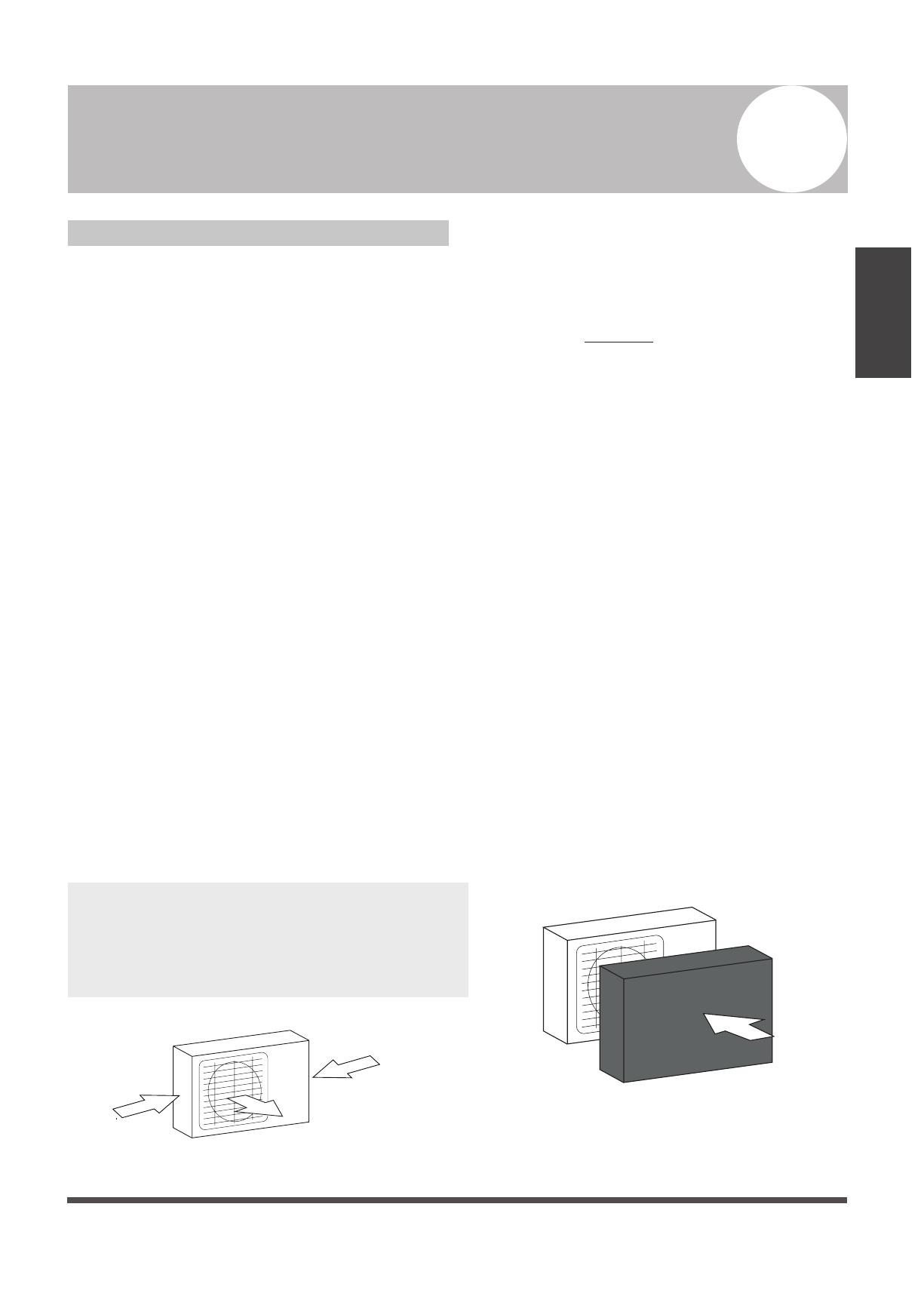
If the location is exposed to strong winds (for
example: near a seaside), the unit must be
placed against the wall to shelter it from the
wind. If necessary, use an awning. (See Fig.
5.1 & 5.2)
Install the indoor and outdoor units, cables
and wires at least 1 meter from televisions or
radios to prevent static or image distortion.
Depending on the radio waves, a 1 meter
distance may not be enough to eliminate all
interference.
Strong wind
Strong wind
Strong wind
Fig. 5.1
Fig. 5.2
5
NOTE:
All the pictures in this manual are for explanation
purpose only. They may be slightly dierent from
the air conditioner you purchased(depend on
model).The actual shape shall prevail.
The support is at and horizontal and can stand
the weight of the outdoor unit. And will no
additional noise or vibration.
It is easy to install the connecting pipes or
cables.
Determine the air outlet direction where the
discharged air is not blocked.
If necessary, install a blind that does not
interfere with the air ow.
During the heating mode, the water drained o
the outdoor unit ,The condensate should be well
drained away by the drain hole to an
appropriate place, so as not to interfere other
people.
The minimum distance between the outdoor
unit and obstacles described in the installation
chart does not mean that the same is applicable
to the situation of an airtight room.
Page 18
Outdoor Unit
Installation
Air Outlet
(Wall or obstacle)
H
(Refer to Fig 5.4, 5.5, 5.6, 5.10 and Table 5.1)
(Refer to Fig 5.7, 5.8, 5.9 and Table 5.2)
A
B
D
W
H
W
H
760x590x285 (29.9x23.2x11.2) 530 (20.85) 290 (11.4)
810x558x310 (31.9x22x12.2) 549 (21.6) 325 (12.8)
845x700x320 (33.27x27.5x12.6) 560 (22) 335 (13.2)
900x860x315 (35.4x33.85x12.4) 590 (23.2) 333 (13.1)
945x810x395 (37.2x31.9x15.55) 640 (25.2) 405 (15.95)
990x965x345 (38.98x38x13.58) 624 (24.58) 366 (14.4)
946x810x420 (37.24x31.9x16.53) 673 (26.5)
403 (15.87)
946x810x410 (37.24x31.9x16.14) 673 (26.5)
403 (15.87)
952x1333x410 (37.5x52.5x16.14) 634 (24.96)
404 (15.9)
952x1333x415 (37.5x52.5x16.34) 634 (24.96)
404 (15.9)
845x702x363 (33.27x27.6x14.3)
540 (21.26)
350 (13.8)
938x1369x392 (36.93x53.9x15.43) 634 (24.96) 404 (15.9)
900x1170x350 (35.4x46x13.8) 590 (23.2) 378 (14.88)
800x554x333 (31.5x21.8x13.1) 514 (20.24) 340 (13.39)
Fix the outdoor unit with anchor bolts (M10)
>60cm / 23.6”
Fix with bolts
Be sure to remove any obstacles that may
block air circulation.
Make sure you refer to Length Specifications
to ensure there is enough room for installation
and maintenance.
>152.4cm / 60”
Page 19
Outdoor Unit
Installation
NOTE: The minimum distance between the
outdoor unit and walls described in the
installation guide does not apply to airtight
rooms. Be sure to keep the unit unobstructed
in at least two of the three directions (M, N, P)
(See Fig. 5.10)
M
N
P
30 cm / 11.8” from back wall
60 cm / 23.6”on right
60 cm / 23.6” above
30 cm / 11.8”on left
200 cm / 78” in front
Fig. 5.10
D
W
Air inlet
Air inlet
Air inlet
Air inlet
(Wall or obstacle)
Table 5.2: Length Specifications of Vertical
Discharge Outdoor Unit (unit: mm/inch)
MODEL
DIMENSIONS
W H D
18 633/25 554/21.8554/21.8
24 633/25 554/21.8554/21.8
36 759/29.8 554/21.8554/21.8
36 633/25 600/23.6600/23.6
48 759/29.8 710/28710/28
60 843/33 710/28710/28
Fig. 5.8
Fig. 5.9
Fig. 5.11
L
H
300 cm / 118” or more
A
60 cm / 23.6”
or more
150 cm / 59”
or more
25 cm / 9.8”
or more
25 cm / 9.8”
or more
Rows of series installation
L H
L 1/2H
L A
25 cm / 9.8” or more
1/2H < L H
30 cm / 11.8” or more
L H
Can not be installed
Table 5.3 The relations between H, A and L
are as follows.
Drain Joint Installation
If the drain joint comes with a rubber seal
(see Fig. 5.12 - A ), do the following:
1. Fit the rubber seal on the end of the drain joint
that will connect to the outdoor unit.
2. Insert the drain joint into the hole in the base
pan of the unit.
3. Rotate the drain joint 90° until it clicks in place
facing the front of the unit.
>45.7cm / 18”
>45.7cm / 18”
>45.7cm / 18”
>45.7cm / 18”
Page 20
Outdoor Unit
Installation
NOTE: Make sure the water drains to a safe
location where it will not cause water damage
or a slipping hazard.
Base pan hole of
outdoor unit
Seal
Drain joint
(A) (B)
Seal
Fig. 5.12
Notes On Drilling Hole In Wall
You must drill a hole in the wall for the
refrigerant piping, and the signal cable that will
connect the indoor and outdoor units.
1. Determine the location of the wall hole
based on the location of the outdoor unit.
2. Using a 65-mm (2.5”) core drill, drill a hole
in the wall.
NOTE: When drilling the wall hole, make
sure to avoid wires, plumbing, and other
sensitive components.
3. Place the protective wall cu in the hole.
This protects the edges of the hole and will
help seal it when you nish the installation
process.
4. Connect a drain hose extension (not included)
to the drain joint to redirect water from the
unit during heating mode.
If the drain joint doesn’t come with a rubber
seal (see Fig. 5.12 - B ), do the following:
1. Insert the drain joint into the hole in the base
pan of the unit. The drain joint will click in
place.
2. Connect a drain hose extension (not included)
to the drain joint to redirect water from the
unit during heating mode.
  • Page 1 1
  • Page 2 2
  • Page 3 3
  • Page 4 4
  • Page 5 5
  • Page 6 6
  • Page 7 7
  • Page 8 8
  • Page 9 9
  • Page 10 10
  • Page 11 11
  • Page 12 12
  • Page 13 13
  • Page 14 14
  • Page 15 15
  • Page 16 16
  • Page 17 17
  • Page 18 18
  • Page 19 19
  • Page 20 20
  • Page 21 21
  • Page 22 22
  • Page 23 23
  • Page 24 24
  • Page 25 25
  • Page 26 26
  • Page 27 27
  • Page 28 28
  • Page 29 29
  • Page 30 30
  • Page 31 31
  • Page 32 32
  • Page 33 33
  • Page 34 34
  • Page 35 35
  • Page 36 36

Klimaire KDIS060-H2G1 Installation guide

Category
Split-system air conditioners
Type
Installation guide

Ask a question and I''ll find the answer in the document

Finding information in a document is now easier with AI