Follett HCC1000A Operation And Service Manual
- Category
- Ice cube makers
- Type
- Operation And Service Manual

HCC1400A, HCC1400W Icemakers
00135830R04
801 Church Lane • Easton, PA 18040, USA
Toll free (800) 523-9361 • (610) 252-7301
Fax (610) 250-0696 • www.follettice.com
Following installation, please forward this manual
to the appropriate operations person.
Operation and Service Manual
Order parts online
www.follettice.com

2
Follett Corporation
Equipment Return Policy
Follett equipment may be returned for credit under the following conditions:
1. The equipment is new and unused.
2. A return authorization number has been issued by customer service within 30 days after shipment.
3. Follett receives the equipment at the factory in Easton, PA within 30 days after issuance of the return authorization number.
4. The equipment must be returned in Follett packaging. If the packaging has been damaged or discarded, Follett will forward,
at the customer’s expense, new packaging.
Note: Return freight charges are the responsibility of the customer. If equipment is returned and is damaged because of
improper packaging, Follett Corporation will not be held responsible.
Credit will be issued when:
The equipment has been inspected by Follett and deemed suitable to be returned to stock.
Note: A 15% restocking charge will be deducted from the credit. If the cost to return the product to stock exceeds 15%, the
actual cost will be deducted.

3
Welcome to Follett Corporation
Specifications
Operation
Cleaning
Weekly exterior care
Monthly condenser cleaning
Semi-annual evaporator cleaning
Service
Icemaker operation
Water system
Electrical system
Normal control board operation
Test points
Time delay and self flushing jumpers
Error faults
Hard error
Soft errors
Relay output indication
Compressor/refrigerant solenoid output
Wiring diagram
Compressor data
Gearmotor data
Resistance of windings
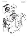
Mechanical system
Evaporator disassembly
Evaporator reassembly
Refrigeration system
Refrigeration pressure data
Refrigeration system diagram
Refrigerant charge size
Refrigerant replacement requirements
Evacuation
Ambients
Ice capacity test
Bin full detection system
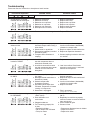
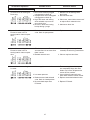
Troubleshooting
Replacement parts
Table of contents
4
5
7
7
7
7
7
12
12
13
14
14
15
15
15
15
15
15
15
16
17
17
17
18
18
20
23
23
23
24
24
24
24
24
25
26
28

4
Welcome to Follett
Follett equipment enjoys a well-deserved reputation for excellent performance, long-term reliability and
outstanding after-the-sale support. To ensure that this equipment delivers the same degree of service, we ask
that you review the installation manual (provided as a separate document) before beginning to install the unit.
Our instructions are designed to help you achieve a trouble-free installation. Should you have any questions or
require technical help at any time, please call our technical service group at (800) 523-936 or (610) 252-7301.
Before you begin
After uncrating and removing all packing material, inspect the equipment for concealed shipping damage. If damage
is found, notify the shipper immediately and contact Follett Corporation so that we can help in the filing of a claim,
if necessary.
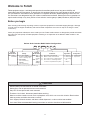
Check your paperwork to determine which model you have. Follett model numbers are designed to provide information
about the type and capacity of Follett equipment. Following is an explanation of the different model numbers in the
1400 series.
Horizon Series Icemaker Model Number Configurations
A Air-cooled, self-contained
W Water-cooled, self-contained
R Air-cooled, remote condensing unit
N Air-cooled, no condensing unit for
connection to parallel rack system
AVSC 1400HC
HC Horizon
Chewblet
®
D Low side 115/60/1
Condenser 208-230/60/1
(remote condensing only)
C 208-230/60/1
(self-contained only)
E 230/50/1
(self-contained only)
Icemaker
Model Series Voltage
Capacity
Model Series Condenser
V Vision™
H Harmony™
B Ice storage
bin
J Drop-in
1000 up to
1036 lbs
(471kg)
1400 up to
1450 lbs
(658kg)
S Satellite-fill™
T Top-mount
Application Configuration
Chewblet is a registered trademark of Follett Corporation, registered in the US.
CAUTION
• Warranty does not cover exterior or outside installations.
• Moving parts. Do not operate with front cover removed.
• Hot parts. Do not operate with cover removed.
• To reduce risk of shock, disconnect power before servicing.
• Most ice machine cleaners contain citric or phosphoric acid, which can cause skin irritation. Read caution
label on product and follow instructions carefully.
• Ice is slippery. Maintain counters and floors around dispenser in a clean and ice-free condition.
• Ice is food. Follow recommended cleaning instructions to maintain cleanliness of delivered ice.

5
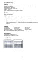
Specifications
Electrical
Each icemaker requires its own separate circuit with electrical disconnect within 10 ft (6m).
Equipment ground required.
Standard electrical – 208-230/60/1
Maximum icemaker fuse – 20 amps each
Amperage – 12 amps
6 ft (2m) NEMA 6-20 cord and plug provided on icemaker
Plumbing
3/8" OD push-in water inlet
3/4" MPT drain
1/4" FPT condenser inlet (water-cooled condenser only)
1/4" FPT condenser drain (water-cooled condenser only)
Notes: 3/4" vented drain line must slope a minimum of 1/4" per foot (6mm per 30.4cm run).
Drain to be hard piped and insulated.
To prevent back flow, do not connect drains.
Separate drains for icemaker and condenser.
Water shut-off recommended within 10 feet (3m).
Follett recommends installation of a Follett water filter system (part# 00130286) in icemaker inlet
water line.
Ambient
Air temperature 100˚F/38˚C max. 50˚F/10˚C min.
Water temperature 90˚F/32˚C max. 45˚F/7˚C min.
Water pressure – potable 70 psi max. (483 kPa) 10 psi min. (69 kPa)
Note: Water-cooled condenser pressure 150 psi (1034 kPa)
Heat rejection
Air-cooled rejects 14,500 BTU/hr to air
Water-cooled rejects 14,500 BTU/hr to water
Ice production
F
C
50
10
60
16
70
21
80
27
90
32
60
16
1591
722
1509
684
1396
633
1364
619
1270
576
70
21
1454
660
1374
541
1270
576
1267
575
1169
530
80
27
1315
596
1197
543
1178
534
1129
512
1071
486
90
32
1187
538
1127
511
1068
484
1020
462
969
440
100
38
1056
479
1030
467
932
423
902
409
870
395
lbs
kg
lbs
kg
lbs
kg
lbs
kg
lbs
kg
Inlet Water Temperature F/C
Ambient Air Temperature F/C
Air-cooled icemaker capacity/24 hrs.
F
C
50
10
60
16
70
21
80
27
90
32
60
16
1356
615
1272
577
1160
526
1065
483
999
453
70
21
1356
615
1272
577
1160
526
1065
483
999
453
80
27
1356
615
1272
577
1160
526
1065
483
999
453
90
32
1356
615
1272
577
1160
526
1065
483
999
453
100
38
1356
615
1272
577
1160
526
1065
483
999
453
lbs
kg
lbs
kg
lbs
kg
lbs
kg
lbs
kg
Water-cooled icemaker capacity/24 hrs.
Inlet Water Temperature F/C
Ambient Air Temperature F/C

6
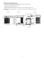
Dimensions and clearances
Entire front of icemaker must be clear of obstructions/connections to allow removal.
1" (26mm) clearance above icemaker for service.
1" (26mm) minimum clearance on sides.
The intake and exhaust air grilles must provide at least 170 sq in (968 sq cm) of open area.
Air-cooled model HCC1400A icemakers – 18" (458mm) minimum clearance between discharge and air
intake-grilles.
C
MOTOR COMPRESSOR THERMALLY PROTECTED
MIN. BRANCH CIRCUIT AMPACITY
MAX. BRANCH CIRCUIT FUSE SIZE
DESIGN PRESSURE HIGH SIDE
Stock Module Identification Plate
FULL LOAD AMPS
REFRIGERANT
Module No.
Product
Service No.
MODEL
CORPORATION
SERIAL NO
VOLTS
AMPS
AMPS
208264
Easton Pennsylvania
HZ
RR
PART NO
CHARGE
LOW SIDE
SINGLE
PHASE
OZ
MADE IN
THE USA
PSIG
NEMA 6-20
right angle
G
Air intake
23.50"
(597mm)
2.72"
(69mm)
23.8" (580mm)
21.05" (535mm)
Air exhaust
both sides
3/8" OD push-in water inlet
3/4" MPT drain
Air exhaust
15.56"
(395mm)
6.97"
(177mm)
2.53"
(64mm)
2.43" (62mm)
29.63" (753mm)
L
U
L
U
NSF
21.28" (541mm)
Front View Side View Back View
Ice transport hose connection
1/4" FPT
condenser inlet
1/4" FPT
condenser drain

7
Operation
Cleaning and preventive maintenance (all models)
Note: Do not use bleach to sanitize or clean the icemaker.
Preventive maintenance
Periodic cleaning of Follett’s icemaker system is required to ensure peak performance and delivery of clean,
sanitary ice. The recommended cleaning procedures that follow should be performed at least as frequently as
recommended, and more often if environmental conditions dictate.
Cleaning of the condenser can usually be performed by facility personnel. Cleaning of the icemaker system,
in most cases, should be performed by your facility’s maintenance staff or a Follett authorized service agent.
Regardless of who performs the cleaning, it is the operator’s responsibility to see that this cleaning is performed
according to the schedule below. Service problems resulting from lack of preventive maintenance will not be
covered under the Follett warranty.
Weekly exterior care
The exterior may be cleaned with a stainless cleaner such as 3M Stainless Steel Cleaner & Polish or equivalent.
Monthly condenser cleaning (air-cooled icemaker only)
1. Use a vacuum cleaner or stiff brush to carefully clean condenser coils of air-cooled icemakers to ensure
optimal performance.
2. When reinstalling counter panels in front of remote icemakers, be sure that ventilation louvers line up with
condenser air duct.
Semi-annual evaporator cleaning (every 6 months)
WARNING
• Wear rubber gloves and safety goggles (and/or face shield) when handling ice machine cleaner or sanitizer.
CAUTION
• Use only Follett approved SafeCLEAN™ Cleaner (part #00132001) and NU-CALGON IMS-II SANITIZER.
• Do not mix Cleaner and Sanitizer solutions together.
• DO NOT USE BLEACH.
• It is a violation of Federal law to use these solutions in a manner inconsistent with their labeling.
• Read and understand all labels printed on packaging before use.
Note: Complete procedure for cleaning an sanitizing MUST be followed. Ice must be collected for 10
minutes before putting ice machine back into service.
1. To clean – Remove cover. Press the CLEAN
button. The machine will drain. Wait for the LO
WATER light to come on (Fig. 1).
LO WATER
C
L
E
A
N
Fig. 1

8
2. Mix 1 gallon (3.8L) 120˚F (49˚C) water and
7 ounces (198g) (one 7 ounce packet of Follett
SafeCLEAN ice machine cleaner, part#-00132001).
Locate cleaning cup. Fill until HI WATER light
comes on (Fig. 2).
Note: Do not use bleach to sanitize or clean the
icemaker.
HI WATER
Fig. 2
12
Fig. 3
LO WATER
N
A
E
L
C
Fig. 4
3. Replace cover on cleaning cup. Wait until machine
restarts. Machine will clean, then flush 3 times in
approximately 12 minutes (Fig. 3).
4. To sanitize – Press CLEAN button. The machine
will drain. Wait for LO WATER light to come on
(Fig. 4).

9
HI WATER
Fig. 5
12
Fig. 6
Fig. 7
5. Mix 1 gallon 120˚F (49˚C) water and 1.6 ounces
(48ml) NU-CALGON IMS-II SANITIZER. Fill until
HI WATER light comes on (Fig. 5).
Note: Do not use bleach to sanitize or clean the
icemaker.
6. Replace cover on cleaning cup. Wait until machine
restarts. Machine will sanitize, then flush 3 times in
approximately 12 minutes (Fig. 6).
7. To clean transport tube – Press power switch OFF
(Fig. 7).

10
Fig. 8
1
2
3
16"
(407mm)
Fig. 9
Fig. 10
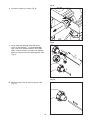
8. Disconnect coupling as shown (Fig. 8).
9. Using disposable food service grade gloves,
insert dry Sani-Sponge
™
(kit part# 00132068).
Next,-insert Sani-Sponge soaked in Nu-Calgon
IMS-II sanitizer solution. Push both Sani-Sponges
down ice transport tube with supplied pusher tube
(Fig. 9).
10. Remove and discard 16" (407mm) pusher tube
(Fig. 10).

11
Fig. 11
Fig. 12
11. Reconnect coupling. Press power switch ON. Ice
pushes Sani-Sponges through tube (Fig. 11).
12. Place a sanitary (2 gallon or larger) container in
bin or dispenser to collect Sani-Sponges and ice
for 10 minutes. Collect 5.5 lbs of ice from unit.
Discard ice and Sani-Sponges (Fig. 12).

12
Service
Icemaker operation (all models)
Follett’s icemaker consists of five distinct functional systems covered in detail as follows:
• Water system
• Electrical control system
• Mechanical assembly
• Refrigeration system
• Bin full
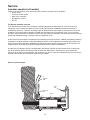
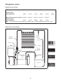
The Horizon icemaker overview
The Follett Horizon icemaker uses a horizontal, cylindrical evaporator to freeze water on its inner surface. The
refrigeration cycle is continuous; there is no batch cycle. The evaporator is flooded with water and the level is
controlled by sensors in a reservoir. A rotating auger (22 RPM) continuously scrapes ice from the inner wall of the
evaporator. The auger moves harvested ice through the evaporator into an ice extrusion canal. The ice is forced
through a restrictive nozzle that squeezes out the water and creates the Chewblet. The continuous extrusion process
pushes the Chewblets through a transport tube into a dispenser or bin.
A solid state PC board controls and monitors the functionality of the ice machine. In addition to sequencing electrical
components, the board monitors various operational parameters. A full complement of indicator lights allows visual
status of the machine's operation. Additionally, the PC board controls the self-flushing feature of the icemaker. The
evaporator water is periodically drained and replenished to remove minerals and sediment.
A unique “bin full” detection system is incorporated in the Horizon icemaker. A switch located at the ice discharge
port of the machine detects the position of the transport tube. When the bin fills up with ice, the transport tube
moves out of the normal running position, and the switch turns the ice maker off. A domed housing at the end of the
transport tube contains the ice extrusion loads during shut down.
water
inlet
auger
compression
nozzle
ice
transport
tube
Harvest system diagram

13
Water system
The water level in the evaporator is controlled by a feed solenoid and level detecting sensors. Referencing the
diagram below, water sensing rods extend down into the reservoir at the end of the evaporator assembly. The
system works via electrical conductivity as follows:
One of the longest probes is a common. When water is between any of the other probes and the common, the
PC board will sense the activation. During normal operation, the water level rises and falls between the Normal
High and Normal Low sensors. As water is consumed to make ice, the level will fall until the Normal Low sensor is
exposed, triggering the water feed solenoid on. Water will fill until the Normal High sensor is activated.
Additional sensors are incorporated in the reservoir for alarm and cleaning/flushing conditions.
Note: The potable water dissolved solids content must be greater than 30 ppm for the water control system to
function properly. If using reverse osmosis water filtration system, ensure T.D.S level is greater than 30 ppm.
Alarm HI
Alarm LO
Normal HI
Common
Normal LO
Normal
operating
range
Water system diagram
Water level diagram

14
Electrical system
Normal control board operation
The PC board indicator lights provide all the information necessary to determine the machine's status. Green
indicator lights generally represent “go” or normal operation; Yellow indicators represent normal off conditions;
Red indicators generally represent alarm conditions, some of which will lock the machine off.
A green light labeled POWER indicates power to the machine. A flashing green light labeled CPU is normal and
indicates that the Central Processing Unit “heart beat” is working. All other normal operation status indicators are
covered as follows:
1. Ice machine is making ice.
2. Ice machine is not making ice.
3. Ice machine is not making ice.
1. Normal running.
2. Normal time delay. When the bin fills with ice, the LOW BIN
light goes out and the refrigeration and auger drive systems
immediately shut down. (Note: The fan motor will continue to
run for 10 minutes to cool condenser) The TIME DELAY light
comes on, initiating the time delay period. When the time delay
expires, the machine will restart provided that the LOW BIN
light is on.
3. Normal purge indicator. After a selected period of ice
making time has elapsed (2 or 6 hours), the ice machine will
automatically self-flush. The compressor will shut down but
the fan and gearmotor will continue to run. After the flush is
complete the machine will refill and start without a time delay.
Ice machine disposition Operating conditions
ON OFF
Legend:
ON or OFF FLASHING
POWER
LOW BIN
AUGER ON
REFRIG ON
PURGE
TIME DELAY
CLEANING
SERVICE
HI AMPS
HI PRESS
DRAIN CLOG
HI WATER
CPU
LO WATER
POWER
LOW BIN
AUGER ON
REFRIG ON
PURGE
TIME DELAY
CLEANING
SERVICE
HI AMPS
HI PRESS
DRAIN CLOG
HI WATER
CPU
LO WATER
POWER
LOW BIN
AUGER ON
REFRIG ON
PURGE
TIME DELAY
CLEANING
SERVICE
HI AMPS
HI PRESS
DRAIN CLOG
HI WATER
CPU
LO WATER

15
Test points:
The Horizon PC board incorporates on-board test points that can be used to determine various electrical
outputs. The test point holes allow a standard probe to be inserted for quick voltage measurement. For 208-230
systems, use TP-4 (L2) as the common for testing outputs for solenoids, motors, etc.
Time delay and self-flushing jumpers:
The duration of the Time Delay period, the time between normal shut down and restart, is jumper selectable.
Jumpers J33 and J34 can be used to select a time delay value of either 1/2, 1, 2, or 3 hours. The factory default
setting is 1 hour. Jumper J32 sets the self-flushing interval to 2 or 6 hours of compressor run time, and J31
either enables or disables self-flushing feature. The factory default setting is enabled flushing every 2 hours.
Error faults:
The Horizon PC board monitors various operating parameters including high pressure, auger gearmotor
amperage limits, clogged drain, and high and low water alarm conditions. There are two types of errors namely
“hard” or “soft”. A hard error is one that shuts the machine off and will not allow restart until the reset button is
pressed. Even cycling power will not reset a hard error. A soft error can either be automatically reset should the
condition rectify, or if power is cycled. Should an error occur, consult the troubleshooting guide in this manual or
a Follett service technician. Note: there are two types of LO WATER and HI AMPS errors as listed below.
Soft errors:
HI AMPS: The PC board monitors the amperage of the auger motor. Should the gear motor experience current
draw above the 3.8 amps limit the machine will shut down and the TIME DELAY, HI AMP, and SERVICE LED’s
will be illuminated. After the time delay the machine will restart and the TIME DELAY, HI AMP, and SERVICE
LED’s will clear.
HI WATER: A sensor in the water reservoir is positioned at the very top of the reservoir cap. Should water rise to
this high alarm sensor, a soft error will occur. The machine will operate with this alarm active, however the water
feed solenoid will not be on. The alarm will turn off should water recede from the sensor.
LO WATER: During operation, the water level cycles between the normal low and normal high sensors. Should
the water be shut off to a running machine, a soft error will occur. The error sequence is as follows: During
operation, the water level falls to the normal low sensor, and when it does the water feed solenoid is energized. If
water is not detected at the normal low sensor within 120 seconds, a soft error will occur. The machine will shut
down, but the water feed solenoid will remain energized. Should water return, it will fill to the normal low sensor
and the machine will resume normal operation. The error will clear automatically.
Hard error:
HI AMPS:
1. “Two strikes” feature. If the gearmotor has a second HI AMP occurrence during the countdown period
(6 hours after a HI AMP time delay) a hard error will occur and the HI AMP and SERVICE LED’s will be
illuminated.
2. No current. To prevent the refrigeration system from running without gearmotor rotation the PC board will
indicate HIGH AMP and SERVICE if the drive relay is energized and there is no current draw.
HI PRESSURE: Should the refrigeration pressure rise above 425 psi, a hard error will occur. Even if pressure
fall-back below the reset point of 295 psi, the error will not clear and the machine will not restart.
DRAIN CLOG: The drain clog sensor, located in the plastic drain pan behind the drain solenoid, will detect the
presence of water just below the top edge of the pan. If water does not properly flow out of the drain pan it will
rise to the sensor, especially during a self-flushing purge cycle.
LO WATER:
1. There is a sensor in the water reservoir that reaches down to the very bottom. The machine will not start if
water is not present at this sensor.
2. A hard error will occur should water not be present within 60 seconds of power up or if the sensors are
disconnected or damaged.
Relay output indication:
Each relay on the board has an indicator light associated with its output. For example, when the relay for the
water feed solenoid is energized, the adjacent indicator light glows green.
Comp/Sol output:
The output for the compressor is labeled COMP/SOL.

16
LE
LE
2
LOW
NORM
6
HIGH
NORM
LE
3
COM
LE
4
ALARM
LE
LOW
5
LE
7
LE
8
CLOG
DRAIN
COM
ALARM
HIGH
WATER LEVEL
OUT (light on)
-V
(3 WIRE)
+V
RETURN
(CONTACT CLOSURE)
BIN
FULL
S3
CLEAN
MOM
S2
PURGE
MAINT
OR
INPUT 2
1
2
3
4
J51
RED / GRAY PAIR
GRAY / GRAY PAIR
J34
1/2 hour
J33
Time Delay
J33
J31
FLUSHING
DISABLED
J34
1 hour
Time Delay
J32
(DEFAULT)
Flushing
2 hours
ENABLED
FLUSHING
(DEFAULT)
(DEFAULT)
J31J32
6 hours
Flushing
1
1
1
1
J24
J22 J23
CONTROL PC BOARD
J21
PURGE (Y)
POWER (G)
LOW BIN (G)
AUGER ON (G)
REFRIG ON (G)
CLEANING (Y)
SERVICE (R)
HI AMPS (R)
HI PRESS (R)
LO PRESS (R)
DRAIN CLOG (R)
TIME DELAY (Y)
LO WATER (R)
CPU (G)
HI WATER (R)
JUMPERS
SWITCH
RESET
TIME DELAY
SELF FLUSH
J34
J33
J32
J31
Time Delay
3 hour
J34
J33
2 hour
Time Delay
J33
J34
00135780
R
1o/230Vac
SIGNAL
RETURN
2
1
J3
GRAY / GRAY PAIR
HI
PRESS
HIGH PRESSURE
OPENS @ EXCESS
P
2
PE
OPEN @ 425 PSI
CLOSE @ 295 PSI
K1
CNO
L1
J7
J4
J5
MOTOR
FAN
J17
J18
J2
BRN
BLU
1
2
3
J50
.6 Amp Max
1/2hp Max
NOC
K3
J6
M2
M1
#2
#12
#1
#3
GRN
#34
CB1
COMP
SOL
FAN
DRV
#19
#18
SNUBBER
20FLA
240Vac
CONTACTOR
L2
2
5
GRN
#7
#8
S1
O I
240Vac / 20FLA
OFF/ON
1
4
~12 Amp DRAW RUNNING
50/60Hz
208V/230Vac
#47
#39
#40
#41
#42
#43
#45
#46
#44
P1
K
11
C2 START
C1 RUN
COMP
S
R
C
6
4
12
5
J10
J9
L2
J11
J12
J8
#11
#31
#30
#33
#32
FCV-1 FCV-2
230Vac
20Watt 20Watt
230Vac
DRAIN
INPUT
WATER
J16
J13
J14
J15
H2O
IN
POTENTIAL
RELAY
H2O
DRN
TP11
TP4
TP7
TP8
TP6
TP5
TP3
WHT
BLK
GRN
AMP
SENSING
D9
D5
D10
D6
D15
BLU
BLK
BRN
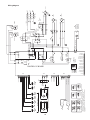
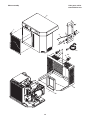
Horizon 1400 Series Self-contained Icemaker
P52
L2
GND
L1
BLK
WHT
#38
#37
#37
#38
#2
WHT
BLK
L1
J52
JUMPERS CAN NOT BE REMOVED FROM PC BOARD. J31 THRU J34
FORM A SERIES CIRCUIT, IF A JUMPER IS REMOVED AND
DISCARDED THE PC BOARD TIMING FUNCTIONS WILL NOT WORK
PROPERLY.
801 CHURCH LANE
EASTON, PA 18040, USA
800-523-9361 OR 610-252-730
1
FOR SERVICE CALL:
ON THE WEB: www.follettice.co
m
JUMPER
Wiring diagram

17
Compressor data
Compressor current draw
Air-cooled
Ambient air temp. 60˚F/16˚C 70˚F/21˚C 80˚F/27˚C 90˚F/32˚C 100˚F/38˚C
8.01A 8.26A 8.77A 9.06A 9.36A
Water-cooled
Condenser water temp 50˚F/10˚C 60˚F/16˚C 70˚F/21˚C 80˚F/27˚C 90˚F/32˚C
9.09A 9.14A 9.06A 9.15A 9.39A
Locked rotor amps 96.8
Gearmotor data
Brother
Gearmotor current 2.8A (nominal)
Locked rotor amps 15 amps
Resistance of windings
208-230 vac gearmotor (Brother) 6.2Ω
Compressor start winding 3.5Ω
Compressor run winding 0.7Ω
Fan motor 38Ω

18
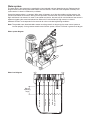
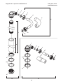
Mechanical system
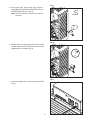
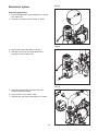
Evaporator disassembly
1. Press PURGE button to purge evaporator, and then
turn power OFF.
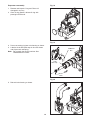
2. Unscrew and remove stream divider as shown.
3. Unplug and remove gearmotor as shown.
4. Remove all traces of anti-seize compound or
petrol-gel from the auger shaft.
Fig. 13
Fig. 14
Fig. 15
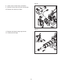
5. Unscrew and disconnect transport tube from
louvered docking assembly.
6. Unplug sensor at the electrical box.
7. Remove vent tube from shuttle housing as shown.

19
Fig. 16
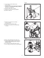
8. Loosen nut on V-band clamp and remove.
9. Remove V-band clamp from front of evaporator.
10. Remove main housing as shown.
Fig. 17
11. Remove and discard mating ring and seal.
12. Carefully remove auger.

20
Lube
with soap
touch
Do not
Cardboard
disc
Fig. 19
3. Press new mating ring into main housing as shown.
4. Lube the shaft with liquid soap in the area shown
and slip on seal and spring.
Note: Do not touch the sealing surfaces. Use
cardboard disk to install.
Fig. 20
5. Reinstall main housing as shown.
Fig. 18
Evaporator reassembly
1. Remove and inspect O ring seal. Discard if
damaged in any way.
2. Clean O ring groove. Lubricate O ring with
petrol-gel and reinstall.
Page is loading ...
Page is loading ...
Page is loading ...
Page is loading ...
Page is loading ...
Page is loading ...
Page is loading ...
Page is loading ...
Page is loading ...
Page is loading ...
Page is loading ...
Page is loading ...
Page is loading ...
Page is loading ...
Page is loading ...
Page is loading ...
Page is loading ...
Page is loading ...
Page is loading ...
Page is loading ...
-
 1
1
-
 2
2
-
 3
3
-
 4
4
-
 5
5
-
 6
6
-
 7
7
-
 8
8
-
 9
9
-
 10
10
-
 11
11
-
 12
12
-
 13
13
-
 14
14
-
 15
15
-
 16
16
-
 17
17
-
 18
18
-
 19
19
-
 20
20
-
 21
21
-
 22
22
-
 23
23
-
 24
24
-
 25
25
-
 26
26
-
 27
27
-
 28
28
-
 29
29
-
 30
30
-
 31
31
-
 32
32
-
 33
33
-
 34
34
-
 35
35
-
 36
36
-
 37
37
-
 38
38
-
 39
39
-
 40
40


Follett HCC1000A Operation And Service Manual
- Category
- Ice cube makers
- Type
- Operation And Service Manual
Ask a question and I''ll find the answer in the document
Finding information in a document is now easier with AI
Related papers
-
Follett HCD1400N Operation And Service Manual
-
-
-
-
-
Follett HMD1000N Operation And Service Manual
-
-
-
-