Aracruz 52AC

Concord Fans Aracruz 52AC, 60AC5ORB Installation guide

  • Hello! I am an AI chatbot trained to assist you with the Concord Fans Aracruz 52AC Installation guide. I’ve already reviewed the document and can help you find the information you need or explain it in simple terms. Just ask your questions, and providing more details will help me assist you more effectively!
A Commitment to Excellence
Part Number: PL-3238 (Revised 05.02.07)
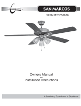
Aracruz
Owners Manual
and
Installation Instructions
®
52AC
2
READ AND SAVE THESE INSTRUCTIONS
Before beginning installation of your new
Concord
®
ceiling fan,
read and follow these safety precautions. If you are not familiar
with national and local electrical codes and basic electrical wiring
procedures, we recommend that you have a qualified electrician
install your new ceiling fan.
Before you begin, TURN OFF THE ELECTRICITY. Determine which cir-
cuit your new fan will be using and remove the fuse or turn off the circuit
breaker at the main electrical panel.
Make sure that all wiring conforms to national and local electrical codes. If
you are in question, obtain a copy of the codes and wire the fan according-
ly. Never leave bare wires uncovered (wire connection), use wire nuts to
cap all connections. Plastic electrical tape is not recommended.
When working with electricity, never take short cuts. Follow the code in
every respect. Basic requirements for a ceiling fan installed with lights are,
120 volts AC - 60Hz, on a grounded circuit with a 15 amp breaker or fuse.
Make sure that your electrical system and choice of location meet these
requirements.
If the location where you plan to install your fan does not already have an
electrical outlet, hire a licensed electrician to run the wiring and install an
outlet box designed for ceiling fans or heavy fixtures. The outlet box
should be able to support a minimum moving weight of 50 pounds and
marked “Acceptable for Fan Support” (Plastic outlet boxes are not recom-
mended for ceiling fan installation).
If you plan to use an existing electrical location, check to make sure that the
outlet box is not PLASTIC, that it is securely attached and able to support
at least 50 pounds of moving weight and marked “Acceptable for Fan
Support”. If you have any questions, outlet boxes and support systems for
ceiling fans are available at most hardware and do-it-yourself centers. In
most cases, your
Concord
®
dealer will have all the necessary products
for the proper and safe installation of your ceiling fan.
The location you choose should have a minimum clearance of 20 inches
from any wall to the blade tip at any point in its rotation and a minimum of
7 feet from blade level to floor and 10 inches from the blades.
3
This ceiling fan was not designed for installation in any location where it
might be exposed to moisture or high humidity. Installation in this type of
location could be UNSAFE, will most likely damage the fan and its finish...
and will VOID YOUR WARRANTY.
Every effort has been made to provide you with proper instructions for the
safe installation of this ceiling fan. You could however, encounter situa-
tions or problems not covered in this manual. Should this occur, please
refer to a do-it-yourself wiring handbook or hire a qualified electrician to
install your fan.
Never attach the blades to your ceiling fan before the fan body is properly
mounted on the ceiling.
Lubrication of your new ceiling fan is not necessary. The ball bearings have
been adequately charged with grease and permanently sealed at the factory
so that, under normal conditions, further attention is not necessary.
Look for Me!
I have safety Tips and
Ideas for installation
To reduce the risk of fire, electrical shock, or personal injury,
mount this fan to an outlet box marked “Acceptable for Fan
Support” and use the Mounting Screws provided with the outlet
box. CA
UTION: Install the primary mounting means and use
only the hardware provided with the fan.
To reduce the risk of personal injury take care not to bend
the
blade carriers. Be careful not to insert foreign objects into rotat-
ing fan blades.
The important safeguards and instructions appearing in this
manual are not meant to cover all possible conditions and situa-
tions that may occur. It must be understood that common sense,
caution and careful attention to detail are factors which cannot
be built into this product. These factors must be supplied by the
person or persons installing, caring for, and operating the unit.
4
Fig. 1
Fig. 2
Have you
TURNED OFF
the Electricity?
Loosen the two canopy mounting screws on the
downside face of the mounting bracket. Back
them out about half way. This will allow for
easier installation of the ceiling canopy later (see
figure 1).
Install the mounting bracket on the electrical
junction box in the ceiling using two machine
screws, two washers and two lock washers (see
figure 1).
The mounting bracket has slotted holes to enable
it to move sideways for proper alignment. Make
sure the mounting bracket is centered over the
electrical junction box and that it is securely
attached (see figure 1).
NO MOVEMENT SHOULD OCCUR
BETWEEN THE MOUNTING BRACKET
AND THE ELECTRICAL JUNCTION BOX.
Step 1 Attach the mounting bracket
Pull the electric wires in the
junction box down through
the mounting bracket and
then bend them up and back
out of the way. This will
leave the mounting bracket
open and ready to receive the
ceiling fan (see figure 2).
If you are using an extended support rod, (longer
than the one supplied with your fan) remove the
half ball from the small support rod that came
with the fan and put it on the extended support
rod. Make sure to retighten the set screw and
insert the safety screw.
Junction Box
Washer
Washer
Screw
Mounting Bracket
5
Loosen the set screws (2) in the support rod cou-
pler located on the top center of the motor hous-
ing (see figure 4) until the inside channel is clear.
Remove and save the safety screw from the cou-
pler.
Place coupler cover over the support rod cover.
Place rubber canopy ring over the coupler cover.
Place the ceiling canopy face down (small end)
over the support rod coupler on the motor hous-
ing.
Slide canopy onto support rod.
Feed the electrical wires from the fan housing
through the support rod.
Thread the support rod into the support rod cou-
pler until the safety screw can be inserted
through the hole in both the rod and coupler.
Insert the safety screw through the hole in the
support rod coupler and support rod then tighten
firmly.
Insert the set screw in the coupler and tighten
firmly.
Step 3 Attach the support assembly
Ceiling Canopy
Half Ball Hanger
Support Rod
Support Rod
Set Screws
Support Rod
Coupler
Coupler Cover
Fig. 4
Safety Screw
Fig. 3
Motor
Motor
Housing
Cover
Insert the motor housing onto motor
Place motor housing cover onto motor, line up
the 3 keyway holes rotate plate; locking it into
place.
Insert single screw and tighten (see figure 3).
Tighten other 3 keyway screws.
Step 2 Attach Motor Housing to Motor
Rubber
Canopy Ring
6
Fig. 5
Remove screws holding clear dust cover down.
Screw bulbs (4) -included with your fan- into the
sockets located in the top of the fan motor hous-
ing (see figure 5).
Place clear dust cover back over bulb area.
Replace screws you removed previously.
Step 4 Putting bulbs in top of fan
Socket
Fig. 6
Notice the half ball on the end of the support rod
is grooved down one side (see figure 6). This
Keyway fits over the small keyway pin on the
inside of the mounting bracket and keeps the
ceiling fan from spinning on the mounting
bracket.
Using your step ladder, lift the fan and place the
half ball in the center of the mounting bracket
with the keyway pin inserted into the keyway on
the ball. Turn the fan left and right slightly to
make sure it is seated on the bracket with the
keyway pin in the keyway (see figure 7).
Trim the lead wires, leaving about six inches of
each wire extending from the support rod (see
figure 8).
Step 5 Hanging the Fan Body
Mounting Bracket
Support Rod
Bulb
Keyway
Dust Cover
Orange or Gray
Blue
White
Black
White
Black
Ground
Ground
7
Ground Wire
Support Rod
Ball Hanger
Mounting
Bracket
Keyway Pin
Ball Hanger
Support Rod
Fig. 7
Fig. 8
Fig. 9
Step 5 Making the Electrical Connections
To operate your ceiling fan with the pull chain(s)
and switches mounted on your fan, follow the
instructions below:
Attach the GREEN wire (connected to the half
ball) to the GROUND
wire in the junction box.
The GROUND wire is usually a bare copper wire
without plastic insulation. It could also be cov-
ered in green plastic insulation (see figure 9).
Attach the BLACK wire and the BLUE wire
from the ceiling fan to the BLACK
wire in the
junction box.
Attach the WHITE wire and ORANGE (GRAY
on some models) wire from the fan to the
WHITE
wire in the junction box.
Fold the connected wires (see figure 9) and push
them up inside the electrical junction box with
the black and blue wires to one side and the white
and green to the other side. Make sure the wire
nuts do not come loose during this operation.
Each of the above connec-
tions should be made as tight
as possible using the proper
size plastic wire nuts. Plastic
electrical tape is not recom-
mended for these connec-
tions.
If you are going to use an RM-08 Control Unit
with this fan, refer to the Installation Manual
for the RM-08 before proceeding further.
8
Mounting
Bracket
Canopy
Canopy
Screws
Screw
Blade
Fig. 10
Fig. 11
Slide the ceiling canopy up into place over the
ceiling mounting bracket. Slide rubber canopy
cover into place. The two screws on the mount-
ing bracket face should slip through the key hole
slots in the canopy (see figure 10).
Step 7 Attaching the Ceiling Canopy,
Depending on how deep the
electrical junction box was
installed in the ceiling, you
may have a slight gap
between the ceiling canopy
and the ceiling.
Step 8 Fan Blade and Blade Arm Assembly
Junction boxes are commonly installed at differ-
ent depths in the ceiling, so we have designed
the mounting bracket and canopy to allow for
this
Most CONCORD fans are supplied with a
reversible blade finish. Choose the blade finish
that you prefer and attach as follow:
Attach each fan blade to a blade arm with four (4)
3/16” x 1/2” washer head screws and four (4)
3/16” screw pads (see figure 11). DO NOT
OVER TIGHTEN THESE SCREWS.
Screws should be tightened until the screw pads
are compressed by the screw head. Hold the
Blade Arm decorative side down
and place the
blade on top with the flat side of the blade facing
down. Each screw is passed through the screw
pad and blade and screwed into the blade arm.
Blade Arm
Rubber
Canopy
Cover
Switch Housing
Mounting Plate
Fan Blade
Pre-Installed Blade
to Motor Screws
9
Fig. 12
Remove the large screws in the face of the
motor. Discard any rubber blocks attached to
these screws. The rubber blocks are installed at
the factory to stabilize the motor during ship-
ment.
Attach each blade to the motor face using the
two screws attached to the blade arm (see figure
12). Take care not to bend the blade arms during
installation. This will cause your fan to wobble
while running.
Step 9 Fan Blade Assembly Installation
Try mounting the blades on opposing sides of the
motor face, This will help keep the fan more
level during blade installation.
Fig. 13
Place switch housing mounting plate onto fan,
line up the 2 keyway holes and rotate mounting
plate; locking it into place.
Insert single screw and tighten.
Tighten other 2 keyway screws (see figure 13).
10
Back off (loosen) the three screws on the electri-
cal housing mounting plate attached to the motor
shaft (see figure 15).
A color coded wire connector (female) is located
inside the electrical switch housing (see figure
14), a male connector extends from the mounting
plate. Align the colors on each connector and
push them together. The connectors are also
notched and will connect only when the colors
are aligned.
Connect the single wire from fan to the single
plug in Switch Housing Unit.
The switch housing has three slotted holes
around the top. Align these holes with the three
screws on the mounting plate. Push the switch
housing up and rotate the the right so the screws
are at the far left of the horizontal slot.
Tighten each screw.
Step 10 Electrical Switch Housing Installation
Check all safety pins, set screws and connec-
tions are properly in place and tight.
Check blade clearance and rotation.
Attach the decorative pull chain tassel(s) to the
switch housing.
Step 11 Final Checks
Motor
Housing
Connector
Switch
Housing
Connector
Fig. 14
Switch Housing
Mounting Plate
Molex Plug
(Male and Female)
Switch Housing
Mounting Plate
Screw
Single
Wire
Plugs
If you are going to use an RM-08 Control Unit
with this fan, refer to the Installation Manual
for the RM-08 before proceeding further.
Switch
Housing
Screw
Fig. 15
11
Figure 16 illustrates the wiring used to control
the fan with a wall switch plus an optional light
fixture controlled at the fixture.
Figure 17 illustrates the wiring used to control
fan with the pull chain on the electrical switch
housing plus an optional light fixture with a wall
switch.
Figure 18 illustrates the wiring used to control
the fan and optional light fixture with separate
wall switches.
Optional Wiring Diagrams
Your dealer carries a number of different types
of CONCORD wall switches that have been
designed and tested for use with our products.
To obtain the best performance electrical com-
ponents should be matched for output, for that
reason, we only recommend the use of CON-
CORD products.
Fan controlled at fan with Light controlled at wall switch
Fan controlled with wall switch and Light controlled at fan
Fan & Lights controlled by wall switch or switches
Fig. 16
Fig. 17
Fig. 18
If you elect to control the motor of your ceiling
fan from a wall switch, remember that the wall
switch will only turn your fan ON or OFF. The
speed can be adjust at the fan.
If you elect to control the speeds of your ceiling
fan from a wall switch, YOU MUST set the
speed switch on the ceiling fan to HIGH speed
and leave it in that setting.
IMPORT
ANT NOTE:
ONLY USE AN OPTIONAL WALL
SWITCH THAT HAS BEEN DESIGNED
FOR USE WITH CEILING FANS
12
© Great 2000 Enterprises, Inc., 2007 • ALL RIGHTS RESERVED •
No part of this publication may be produced, transmitted, transcribed, stored in a retrieval system, or translated into any language
in any form by any means without the written permission of Great 2000 Enterprises, Inc..
Concord Fans and Lighting is a division of Great 2000 Enterprises, Inc.
®
Safety Screw
Mounting
Plate Screw
Switch Housing
Screw
Blade to
Arm Screw
Ceiling
Canopy
Support Rod
Fan Body
Fan Blade
Set Screw
Forward/Reverse
Switch
Blade Arm
Switch
Housing
Your new CONCORD ceiling fan is now ready for use.
Reset your circuit breaker and restore power to the cir-
cuit. See the Operation Instructions below to review the
function of each control on your fan.
The pull chain located on the switch housing (see figure
13) controls the speed of your fan. When the fan is OFF,
pull the chain once for HIGH speed, twice for MEDI-
UM speed, three times for LOW speed and fourth time
to turn it off again.
The slide switch located on the switch housing (see fig-
ure 14) controls the direction of blade rotation. The
LEFT position sets the blades in REVERSE rotation (air
moves UP). The RIGHT position sets the blades in
FORWARD rotation (air moves DOWN).
Operation Instructions
Maintenance
Your fan requires very little maintenance. Cleaning of
the housing should be done with a damp soft cloth (NO
CLEANING AGENTS). On the blades, use a duster or
dry cloth because any moisture could cause the blades
to warp.
Motor
Housing
cover
Coupler
Cover
Switch
Housing
Mounting
Plate
Canopy
Screw
Motor
Rubber
Canopy
Cover
Housing
Cover
Screw
/