Page is loading ...

READ AND SAVE THESE INSTRUCTIONS
INSTRUCTIONS FOR MOUNTING LIGHT FIXTURES
K2C (
INCANDESCENT)
or K1C (
HALOGEN)
WARNING: To reduce the possibility of electrical shock, be sure that the power is turned off at its source
(fuse or circuit breaker)
. All electrical components must be installed in accordance with national and local
electrical codes. To reduce the risk of fire and electrical shock, use this light fixture only with UL Listed
Casablanca ceiling fans indicated as adaptable on the chart included with these instructions.
continued . . .
INSTALLATION
SWITCH
HOUSING
CAP
8-32 SCREW
FIG. 2
WIRE NUT
PLASTIC PLUG
BLUE WIRE
KNURL NUT
PULL-CHAIN
SWITCH
FIG. 1
WHITE WIRE
FIG. 3
5 BEADS
PULL CHAIN
w/NYLON TUBING
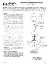
1. Remove the cap from fan by removing two brass 8-32
screws and save these screws for attaching light fixture. This
cap will not be reused. Remove plastic wire nuts from switch
housing wires and strip 1/2" insulation from both wires (black
or blue, and white). See FIG. 1
NOTE: For K2C (
incandescent)
Light Fixture: If installing
this light fixture on a 3 Speed pull-chain model fan, a
separate pull-chain switch (included with the fan) must
be installed. Refer to the following installation instruc-
tions. Otherwise, for K1C (
halogen)
Light Fixture installa-
tion skip to step 5.
2. Remove the plastic plug from the fan switch housing.
Install the light on-off switch by inserting the chain through
hole, from the inside. Pass the switch threads into the hole
and screw the knurl nut onto the switch. Hand tighten firmly.
See FIG. 2
3. Attach the blue wire from the fan (labeled D1-OPTION) to
one of the blue wires on the switch by twisting the bare ends
of the wires together. Secure the splice by threading on one
of the wire nuts provided. Test the secureness of the splice
by pulling on the wire nut. Check that there is no bare wire
showing from the wire nut then cover connection with electri-
cal tape.
4. Count 5 beads away from the pull chain switch and cut the
pull chain. Attach the beaded pull chain with nylon tubing to
the switch. Repeat installation of the beaded pull chain with
nylon tubing for the fan speed switch already attached to the
switch housing. See FIG. 3
CAUTION: Use only incandescent
light bulbs with K2C light fixture
and only halogen light bulb with
K1C light fixture.
BEFORE YOU START:
• THE K1C LIGHT FIXTURE (HALOGEN) NOT FOR USE ON 3 SPEED
PULL-CHAIN MODEL FANS. (MODEL NUMBERS ENDING WITH "D")
• This switch housing may or may not have electronics in it.
• K2C and K1C for use with G106, G107, G108, G109, and G110 Glass
Shades (sold separately).

5. Thread the two 8-32 screws half way into the two threaded
holes on the switch housing. See FIG. 4
6. While holding light fixture up to the fan, attach the wires
from the fan switch housing and the wires from the light fixture
together (black-to-black or blue-to-black and white-to-white)
by twisting the bare ends of the wires together. Then secure
the splices by threading on the porcelain wire nuts provided.
Test the secureness of each splice by pulling on the wire nut.
Check that there is no bare wire showing from the wire nut
then cover both connections with electrical tape.
7. Align the two 8-32 screws on the switch housing with the
two key slots on the housing cover. Rotate light fixture
clockwise, make certain screw heads have rotated to the
narrow end of the slot.
CAUTION: Make sure no wires are pinched between light
fixture and switch housing. Tighten the screws to secure
light fixture.
8. Install the light bulbs. Do not exceed the maximum
wattage indicated on the light fixture.
CAUTION: Make certain to remove dust and oil from the
halogen light bulbs after installation. Failure to do so will
shorten bulb life.
9. Align the three (3) indents in the glass with the three (3)
tabs in the shade holder, push glass up gently and turn to the
right (clockwise) until the glass is locked in place.
See FIG. 5
(Skip step 10 if this light fixture is not intended for
mounting to a 3 speed pull-chain fan)
10. For 3 speed fan series. Connect the fob pull chain.
Repeat for both switches. See FIG. 6
FIG. 4
FIG. 6
SWITCH
HOUSING
8-32 SCREW
PORCELAIN
WIRE NUT
KEY SLOT
LIGHT
FIXTURE
LIGHT BULB
GLASS
(NOT INCLUDED)
FOB PULL
CHAIN
CAUTION: Make sure no wires are pinched
between light fixture and switch housing.
INSTALLATION
FIG. 5
INDENT
(GLASS)
TAB
(SHADE HOLDER)
P/N 1943930 REV.B P/D JUN96PDG 8A265
/